Sign In
Upload
Manuals
Brands
Tektronix Manuals
Portable Generator
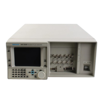
HFS 9010
Tektronix HFS 9010 Manuals
Manuals and User Guides for Tektronix HFS 9010. We have
1
Tektronix HFS 9010 manual available for free PDF download: User Manual
Tektronix HFS 9010 User Manual (340 pages)
Stimulus System
Brand:
Tektronix
| Category:
Portable Generator
| Size: 23 MB
Table of Contents
Table of Contents
7
Figure 1-4: the Save/Recall Menu
10
Figure 1-6: the Time Base Menu
10
Figure 2-9: the Pulse Menu
10
General Safety Summary
16
Injury Precautions
16
Product Damage Precautions
16
Safety Terms and Symbols
17
Certifications and Compliances
18
Related Manuals
20
Getting Started
23
Product Description
23
Figure 1-1: MAIN MENU Button Location
24
Figure 1-2: Main Menu Display
25
Figure 1-3: the SELECT and Arrow Buttons
25
Figure 1-5: the Reset Verification Dialog
27
Figure 1-7: Time Base Relationships
28
Figure 1-8: Mode Set to Auto-Burst
29
Figure 1-9: the Time Base Menu after Adjustment
30
Figure 1-10: Pulse Generator, Data Time Generator, and Time Base Controls and Connectors
32
Figure 1-11: Setting the Signal Type
34
Figure 1-12: Viewing Channel Data
35
Menu Navigation
41
Figure 2-1: the Cal/Deskew Menu
44
Channel Names
46
Figure 2-2: Channel Locations
46
Figure 2-3: Channel Controls on an HFS 9PG2 Card
47
Figure 2-4: Channel Controls on an HFS 9DG1 Card
47
Figure 2-5: Channel Controls on an HFS 9DG2 Card
47
Selecting Channels
48
Figure 2-6: Pulse Menu, Showing Channel Selection
48
Figure 2-7: Levels Menu, Showing Channel Selection
49
Figure 2-8: Signal Menu, Showing Channel Selection
49
Turning Channels on and off
51
Naming a Channel
51
Figure 2-10: the Signal Menu
51
Figure 2-11: the Signal Name Dialog Box
52
Figure 2-12: Signal Menu after Entering Signal Name
52
Figure 2-13: Naming a Bus
53
Figure 2-14: Viewing a Bus by Group
53
Figure 2-15: Assigning Signal Type
54
Changing Display Order
54
Figure 2-16: Changing the Display Order
54
Figure 2-17: the Data Edit Menu
55
Figure 2-18: the Vector Menu
56
Figure 2-19: the Data Fill Menu
58
Figure 2-20: a Block Filled with Fill Scale Set to 1
59
Figure 2-21: a Block Filled with Fill Scale Set to 3
60
Channel Delay
62
Operator Controls
68
Table 2-1: Output Voltage Limits
72
Phase Lock
76
Commands
81
Pulse Generators
82
Voltage Levels
83
Pulse Timing
84
Saved Settings
94
Table 2-2: Logic State of Outputs When Time Base Stopped
100
Single-Step Operation
100
Manual Trigger
101
Trigger out
102
Setting up the Instrument
107
Using the GPIB Interface
107
Command Syntax
115
Table 3-1: BNF Symbols and Meanings
115
Command and Query Structure
115
Table 3-2: Command Message Elements
116
Table 3-3: Comparison of Header on and off Responses
117
Command Entry
117
Argument Types
119
Block Arguments
121
Data Formats
125
Syntax Diagrams
126
Common Commands and Queries
127
Table 3-4: Commands Common to All GPIB Devices
127
Table 3-5: HFS 9000 Device Commands and Parameters
128
Table 3-6: FACTORY Front Panel Settings
142
Table 3-7: FACTORY Time Base Settings
143
Table 3-8: FACTORY Pulse and Data Time Generator Settings
143
Table 3-9: FPAN:KEY Front Panel Key Equivalents
156
Related Commands
164
Rs232:Baud
195
Rs232:Parity
199
Signal:data
207
Signal Type
210
Table 3-10: Results from *TST
223
Vector:data
227
Status and Events
235
Registers
235
Table 3-11: SESR Bit Functions
236
Table 3-12: SBR Bit Functions
237
Queues
239
Event Handling Sequence
239
Conflicts
240
Messages
241
Table 3-13: no Event Messages
241
Table 3-14: Command Error Messages - CME Bit 5
242
Table 3-15: Execution Error Messages - EXE Bit 4
243
Table 3-16: Device Error Messages - DDE Bit 3
244
Table 3-17: System Event Messages - QYE Bit 2
244
Table 3-18: Execution Warning Messages - EXE Bit 4
244
Programming Examples
245
Example 1: Setting up a Pulse Channel
245
Example 2: Command/Query Usage with Error Handling
247
Example 3: Interacting with a User
250
Appendix A: Accessories
254
Standard Accessories
254
Optional Accessories
255
Power Cord Options
255
Appendix B: Specifications
256
Nominal Traits
256
Table B-1: Nominal Traits - HFS 9PG1 Output Performance
256
Table B-2: Nominal Traits - HFS 9PG2 Output Performance
257
Table B-3: Nominal Traits - HFS 9DG1 Output Performance
258
Table B-4: Nominal Traits - HFS 9DG2 Output Performance
258
Table B-5: Nominal Traits - Time Base
259
Table B-6: Nominal Traits - Performance to External Frequency Reference
259
Table B-7: Nominal Traits - Output Edge Placement Performance
260
Table B-8: Nominal Traits - Transducer in Performance
260
Table B-9: Nominal Traits - Skew Cal in Performance
260
Table B-10: Nominal Traits - Trigger in Performance
261
Table B-11: Nominal Traits - Trigger out Performance
261
Table B-12: Nominal Traits - Power Requirements
261
Table B-13: Nominal Traits - System Memory Performance
261
Warranted Characteristics
263
Typical Characteristics
266
Appendix C: Interface Specifications
270
Interface Messages
270
Character Set (ASCII Chart
271
Reserved Words
272
Using Debug Mode
273
GPIB Function Subsets
274
Wiring for Alternate RS-232-C Configurations
275
Appendix D: Error Messages
278
Appendix E: Packing for Shipment
280
Appendix F: Performance Verification
282
Required Test Equipment
282
Test Record
283
Verification Sequence
292
Self Test
292
Calibration
293
Check Procedures
294
Frequency Accuracy
312
Advertisement
Advertisement
Related Products
Tektronix HFS 9000
Tektronix HFS9DG1
Tektronix HFS9DG2
Tektronix HDVG1
Tektronix HDLG7
Tektronix HFS 9003
Tektronix HFS 9009
Tektronix HDST1 HD-SDI
Tektronix HC100
Tektronix H
Tektronix Categories
Test Equipment
Measuring Instruments
Amplifier
Portable Generator
Printer
More Tektronix Manuals
Login
Sign In
OR
Sign in with Facebook
Sign in with Google
Upload manual
Upload from disk
Upload from URL