Table of Contents
Advertisement
Quick Links
Robot Controller Unit
MRCU Series
Technical Reference
1
Introduction .............................. 2
2
Safety precautions ................... 3
3
Precautions for use ................... 5
4
Preparation ................................ 6
5
Installation ................................. 8
6
Connection ................................ 9
Thank you for purchasing an Oriental Motor product.
This document describes product handling procedures and safety precautions.
• Please read it thoroughly to ensure safe operation.
• Always keep the document where it is readily available.
7
Operation ................................. 14
8
9
Troubleshooting ..................... 17
10 Cable and accessories ............ 19
11 Specifications .......................... 22
TN-MRCUE-2
Advertisement
Table of Contents

Related Manuals for Oriental motor MRCU Series


Summary of Contents for Oriental motor MRCU Series
-
Page 1: Table Of Contents
Installation ......... 8 11 Specifications ......22 Connection ........ 9 Thank you for purchasing an Oriental Motor product. This document describes product handling procedures and safety precautions. • Please read it thoroughly to ensure safe operation. • Always keep the document where it is readily available. -
Page 2: Introduction
The product described in this document is designed and manufactured to be incorporated in general industrial equipment. Do not use for any other purpose. Oriental Motor Co., Ltd. is not responsible for any compensation for damage caused through failure to observe this warning. -
Page 3: Safety Precautions
Safety precautions Safety precautions The precautions described below are intended to ensure the safe and correct use of the product, and to prevent the customer and others from exposure to the risk of injury. Use the product only after carefully reading and fully understanding these instructions. - Page 4 Safety precautions Operation • Turn off the power supply of the controller in the event of a power failure. Failure to do so may result in injury or damage to equipment. • Turn all input signals to the controller OFF before turning on the power supply. Failure to do so may result in injury or damage to equipment.
-
Page 5: Precautions For Use
Precautions for use Precautions for use This chapter explains restrictions and requirements the user should consider when using the product. z When conducting the insulation resistance measurement or the dielectric strength test, be sure to disconnect the controller from other products. Conducting the insulation resistance measurement or the dielectric strength test with the controller and other products connected may result in damage to the product. -
Page 6: Preparation
Preparation Preparation Checking the product Verify that the items listed below are included. Report any missing or damaged items to the Oriental Motor sales office from which you purchased the product. • Controller..........1 unit How to identify the product model Check the model against the model shown on the nameplate. -
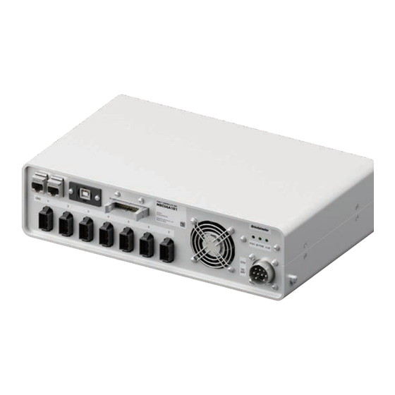
Page 7: Names And Functions Of Parts
Preparation Names and functions of parts EtherNet/IP communication connectors M-PWR USB communication connector I/O signal connector (CN3) (Green) (Green) (Red) Power supply connector (CN1) Motor/encoder/electromagnetic brake connector (CN2) Type Name Description EtherNet/IP communication Connects a scanner with the EtherNet/IP cable. connectors Connects a PC in which the MRC Studio software USB communication connector has been installed. -
Page 8: Installation
Installation Installation Installation location The controller is designed and manufactured to be incorporated in equipment. Install it in a well-ventilated location that provides easy access for inspection. The location must also satisfy the following conditions: • Inside an enclosure that is installed indoors (provide vent holes) •... -
Page 9: Connection
Main power supply Robot breaker *2 *1 This is Oriental motor cable. Please purchase separately. *2 It is recommended that a circuit breaker or a circuit protector is connected because incorrect wiring may cause the internal input circuit to short-circuit. - Page 10 Connection „ Recommended Connectors Part number: NR-2410-PF, NR-2410CPS-PF (Nanaboshi Electric Mfg.Co.,Ltd.) „ Pin assignment The figure shows the view from the insertion side of contacts. Please wire all No.1 to 8 and 10 according to the instructions. Name Main power supply 1 Main power supply 2 Main power supply 3 GND (Main power supply 1)
- Page 11 Connection Series Model Power supply current capacity DR20 0.4 A or more DR Series DR28 1.3 A or more DRSM42 1.5 A or more DRS2 Series DRSM60 2.6 A or more 0.4 A or more EH Series 1.4 A or more L Series LM2, LM4 3.7 A or more...
-
Page 12: Connecting The Usb Cable
Connection Connecting the USB cable Using a USB cable with the following specifications, connect a PC in which the MRC Studio software has been installed to the USB communication connector. Specification USB2.0 (Full speed) Length: 3 m (9.8 ft.) or less Cable Shape: A to B •... - Page 13 Connection Noise elimination measures For noise elimination measures, refer to the Robot Controller MRC01 USER MANUAL.
-
Page 14: Operation
Operation Operation This part explains contents to be performed before starting operation. Operation preparation flow Use the MRC Studio software to prepare for operation. Set the information of the robot with the MRC Studio software. Setting of robot (Details “7-2 Setting of robot”) ↓... - Page 15 Operation 5. Follow the on-screen instructions to set “Controller setting”, “Selection of robot type, ” and “Setting of end effector. ” 6. In “Driver connection setting”, perform STEP 1 and then proceed to STEP 3. Since the switches on the driver body have already been set for this product, there is no need to perform STEP 2.
-
Page 16: Inspection And Maintenance
Inspection It is recommended that periodic inspections are conducted for the items listed below after each operation of the robot. If an abnormality is found, discontinue any use and contact your nearest Oriental Motor sales office. „ Inspection item • Check if the openings on the controller are clogged. -
Page 17: Troubleshooting
Troubleshooting Troubleshooting This part explains alarm and information functions. Alarms This controller has the alarm function to protect from temperature rise, poor connection, error in operation, and the like. If an alarm is generated, the ALM-A output is turned ON and the ALM-B output is turned OFF to stop the robot. The ALM LED blinks in red simultaneously. - Page 18 Troubleshooting „ Clearing information How to clear the information can be set with the “Information auto clear” parameter. z When the “Information auto clear” parameter is set to “1: Enable” (initial value) The generated information will automatically be cleared if the condition to clear information is satisfied. z When the “Information auto clear”...
-
Page 19: Cable And Accessories
Cable and accessories 10 Cable and accessories 10-1 Connection cables (For cable type) „ Connection cables/Flexible connection cables (For AZM14, AZM15, AZM24, AZM26) These cables are used when connecting a motor and a controller. If the cable needs to bend, such as in a robot arm, use a flexible cable. z Connection cables z Flexible connection cables For motor/encoder... - Page 20 Cable and accessories 10-2 Connection cables (For connector type) „ Connection cables/Flexible connection cables These cables are used when connecting a motor and a controller. The model name of the connection cable varies depending on the outlet direction from the motor. Refer to the figures below.
- Page 21 Cable and accessories z Extension cables z Flexible extension cables Length Length Model Model [m (ft.)] [m (ft.)] CCM010Z2ADFT 1 (3.3) CCM010Z2ADRT 1 (3.3) CCM030Z2ADFT 3 (9.8) CCM030Z2ADRT 3 (9.8) 5 (16.4) 5 (16.4) CCM050Z2ADFT CCM050Z2ADRT 10-3 Accessories „ Relay contact protection parts/circuits z CR circuit for surge suppression This product is effective to suppress the surge which occurs in a relay contact part.
-
Page 22: Specifications
11 Specifications 11-1 Product specifications Input voltage 24 VDC±5 % 3 axes: 11.3A (Maximum) 4 axes: 15A (Maximum) Power supply Input current 5 axes: 18.7A (Maximum) 6 axes: 22.4A (Maximum) 7 axes: 26.1A (Maximum) Field network EtherNet/IP • Number of input points: 8, photocoupler Control input •... - Page 24 If a new copy is required to replace an original document that has been damaged or lost, please contact your nearest Oriental Motor sales office. • Oriental Motor shall not be liable whatsoever for any problems relating to industrial property rights arising from use of any information, circuit, equipment or device provided or referenced in this document.
Need help?
Do you have a question about the MRCU Series and is the answer not in the manual?
Questions and answers