Table of Contents
Advertisement
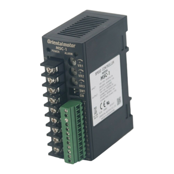
Speed Controller
MSC-1
OPERATING MANUAL
Thank you for purchasing an Oriental Motor product.
This Manual describes product handling procedures and safety precautions.
• Please read it thoroughly to ensure safe operation.
• Always keep the manual where it is readily available.
Table of contents
1 Introduction ............................... 2
2 Safety precautions .................... 4
3 Precautions for use .................. 5
4 Installation ................................ 6
4.1
Location for installation .................6
4.2
Installation method ........................6
4.3
4.4
with EMC Directive ........................7
5 Connection ............................... 9
5.1
Connection example .....................9
5.2
I/O signals ...................................12
6 Basic operations ..................... 13
6.1
Run/stop ......................................13
6.2
Setting the operating speed ........13
6.3
deceleration time .........................14
6.4
2-speed operation .......................14
6.5
Timing chart .................................15
6.6
Multi-motor control ......................15
6.7
instantaneous stop ......................16
6.8
stop .............................................16
7 Alarms .................................... 17
8 Inspection ............................... 18
actions .................................... 19
HP-5051-7
Advertisement
Table of Contents

Subscribe to Our Youtube Channel
Related Manuals for Oriental motor MSC-1


Summary of Contents for Oriental motor MSC-1
-
Page 1: Table Of Contents
Speed Controller MSC-1 OPERATING MANUAL Thank you for purchasing an Oriental Motor product. This Manual describes product handling procedures and safety precautions. • Please read it thoroughly to ensure safe operation. • Always keep the manual where it is readily available. -
Page 2: Introduction
Also read the OPERATING MANUAL for applicable motor. „ Standard and CE Marking „ The MSC-1 is recognized by UL, and affixed the CE Marking (Low Voltage Directive and EMC Directive) under the EN Standards. • Applicable Standards Applicable Standards Cettification Body Standards File No. - Page 3 Introduction „ Names and functions of parts „ POWER LED (Green) ALARM LED (Red) Internal potentiometer (VR1) Main circuit terminal (TB1) Acceleration time potentiometer (VR2) Deceleration time potentiometer (VR3) Not used (SW1-2) Speed command voltage select switch (SW1-1) Control circuit terminal (CN1) DIN lever Name Description...
-
Page 4: Safety Precautions
Safety precautions 2 Safety precautions The precautions described below are intended to prevent danger or injury to the user and other personnel through safe, correct use of the product. Use the product only after carefully reading and fully understanding these instructions. Handling the product without observing the instructions that accompany a "WARNING"... -
Page 5: Precautions For Use
• DC voltage source shall be of Class 2 type. • Install device in pollution degree 2 environment. • Always use this speed controller in combination with a compatible motor by Oriental Motor. The compatible motors listed in this manual are recognized by UL and provide an overheat protection function based on thermal protection or impedance protection. -
Page 6: Installation
Installation 4 Installation This chapter explains the installation location, installation methods and measures against noise of the speed controller. Location for installation The speed controller is designed and manufactured to be installed within another device. Install it in a well-ventilated location that provides easy access for inspection. The location must also satisfy the following conditions: •... -
Page 7: Installing An External Potentiometer (Sold Separately)
Installation Installing an external potentiometer (Sold separately) Install an accessory external potentiometer (sold separately) as shown below. Variable resistor Insulation sheet Mounting plate • Reference mounting hole Dial plate dimensions [Unit: mm (in.)] Setscrew (M4) Tightening torque: 7.5± (0.3± 0.02 0.4 N·m (3.5 lb-in) Dial Ø3 (0.12) - Page 8 Installation „ Connecting mains filter for power supply line „ • Connect a mains filter in the AC power supply input to prevent the noise generated in the speed controller from propagating externally through the power supply line. For a mains filter, use MC1210 (TDK-Lambda Corporation) or equivalent product.
-
Page 9: Connection
Connection „ Example of motor and speed controller installation and wiring „ Motor Speed controller Ferrite Motor cable core [10 m (32.8 ft.)] Cable Mains clamp Ferrite Cable filter Power supply clamp core cable Control cable [2 m (6.6 ft.)] Capacitor Grounded plate 5 Connection... - Page 10 Connection „ Connecting the main circuit terminal (TB1) „ • Applicable cable size: AWG18 (0.75 mm ) or more * Applicable crimp terminal * AWG20 to 14 (0.5 to 2.0 mm ) for capacitor connection Ø3.2 (Ø0.13) or more • Terminal block screw size: M3 •...
- Page 11 Connection „ Connection diagram „ The connection diagram shown here is an example that the operating speed is set using an external speed potentiometer. Speed controller Power supply Fuse 100-115 VAC Main circuit TB1 Blue Rate generator Blue 200-230 VAC Circuit breaker White Motor...
-
Page 12: I/O Signals
Connection I/O signals „ Input signals „ The speed controller input signals are photocoupler inputs. „ Output signals „ The speed controller output signals are transistor/open-collector output. Connect the current-limiting resistor to keep the SPEED-OUT output and ALARM-OUT output at maximum 10 mA and 40 mA, respectively. -
Page 13: Basic Operations
Basic operations 6 Basic operations This chapter explains the basic operations of the speed controller. Run/stop When turning the FWD input or REV input ON, the motor will rotate at the set speed. When turning the FWD input or REV input OFF while the motor operates, the motor will coast to a stop. -
Page 14: Setting The Acceleration Time And Deceleration Time
Basic operations „ Operating speed characteristics (representative values) „ Internal potentiometer External potentiometer External DC voltage 1800 1800 1800 1500 1500 1500 1000 1000 1000 20 40 60 80 100 Dial Dial 60 Hz DC voltage [V] 50 Hz Setting the acceleration time and deceleration time The acceleration/deceleration time can be adjusted to prevent the load from receiving a shock upon starting, stopping or a change in speed. -
Page 15: Timing Chart
Basic operations Timing chart The chart below is an example of setting the internal potentiometer to 1200 r/min and external potentiometer to 100 r/min and switching the speed between these two levels. FWD input 10 ms or more REV input INT/EXT input Run/Speed change/ Run/... -
Page 16: Repeated Cycle Of Operation/Instantaneous Stop
Basic operations Resistance (VRx) when the number of speed controllers is n: Resistance (VRx) = 20/n (k Ω ), n/4 (W) Example: If two speed controllers are used Resistance (VRx) = 20/2 (k Ω ), 2/4 (W), resistance (VRx) is calculated as 10 k Ω , 1/2 W. „... -
Page 17: Alarms
Alarms 7 Alarms When the protective function is actuated and an alarm generates, the ALARM-OUT output will turn OFF. The motor coasts to a stop and once the motor has stopped, the motor output shaft becomes free. At the same time, the ALARM LED will start blinking. The cause of the alarm can be checked by counting the number of times the ALARM LED blinks. -
Page 18: Inspection
Inspection „ Timing chart „ The timing chart shown here is an example when the thermal protector is activated and the motor overheat alarm is generated. AC power supply Control DC power supply 10 ms or more *3 Approx. 100 ms or more FWD input or REV input OPEN Thermal protector... -
Page 19: Troubleshooting And Remedial Actions
Troubleshooting and remedial actions 9 Troubleshooting and remedial actions During motor operation, the motor or speed controller may fail to function properly due to an improper speed setting or wiring. When the motor cannot be operated correctly, refer to the contents provided in this section and take appropriate action. - Page 20 If a new copy is required to replace an original manual that has been damaged or lost, please contact your nearest Oriental Motor branch or sales office. • Oriental Motor shall not be liable whatsoever for any problems relating to industrial property rights arising from use of any information, circuit, equipment or device provided or referenced in this manual.
Need help?
Do you have a question about the MSC-1 and is the answer not in the manual?
Questions and answers