Table of Contents
Advertisement
Quick Links
GDI-6880-02
8 Person FAR Infrared Sauna
OWNER'S MANUAL
INFRARED MODEL SAUNA
FOR INDOOR USE ONLY
240V/30AMP DEDICATED CIRCUIT/RECEPTACLE REQUIRED
Carefully and thoroughly read this Owner's Manual before using/operating
the sauna. We recommend keeping this Owner's Manual for regular review
and future reference. Follow your local codes and ordinances. Models,
Parts and accessories may vary and are subject to change.
1
Advertisement
Table of Contents

Related Manuals for GoldenDesigns GDI-6880-02


Summary of Contents for GoldenDesigns GDI-6880-02
- Page 1 GDI-6880-02 8 Person FAR Infrared Sauna OWNER’S MANUAL INFRARED MODEL SAUNA FOR INDOOR USE ONLY 240V/30AMP DEDICATED CIRCUIT/RECEPTACLE REQUIRED Carefully and thoroughly read this Owner’s Manual before using/operating the sauna. We recommend keeping this Owner’s Manual for regular review and future reference. Follow your local codes and ordinances. Models,...
- Page 2 Thank you for your purchase. As you remove the parts from the boxes, be sure to examine them for damages. If your unit has any damages or missing parts, please contact Golden Designs Inc. See the Warranty section for more information. A Certified Licensed Electrician will be needed to install the electrical wiring.
-
Page 3: Table Of Contents
TABLE OF CONTENTS Packing List Visual Assembly Diagram Schematics Schematic Layout Dimensional Diagram Screw Identification and Location Chart Highlights Assembly Instructions Operating the Sauna Tips for Using Your Sauna Safety Instructions Safeguards for Your Sauna Troubleshooting Guide Maintenance Warranty Warranty Card WARNING: Visually inspect all heaters before assembly to make sure they are not damaged. -
Page 4: Are Infrared Rays Safe
What Are Infrared Rays? Infrared is the band of light we perceive as heat. We cannot see this band of light with the naked eye, but we can feel this type of light in the form of heat. Our sun produces most of its energy output in the infrared segment of the spectrum. - Page 5 panel, and our Near Zero EMF/ carbon panels range at less than 3mG at about two inches from the heater panel. EMF Levels from Common Homes Sources After many years and numerous studies on EMF exposure, no government body including the Occupational Safety and Health Administration (OSHA) have established permissible exposure limits (PEL).
-
Page 6: How It Works
HOW IT WORKS Infrared Saunas differ from traditional saunas in that they use infrared radiant energy to directly penetrate into the body's tissue to produce perspiration. Traditional saunas use steam to heat the air inside the sauna, which then heats your body until you begin to perspire. -
Page 7: Visual Assembly Diagram
READ ALL INSTRUCTIONS THOROUGHLY BEFORE ASSEMBLY GDI-6880-02 – Assembly Diagram *THE PICTURES AND DIAGRAMS SHOWN WITHIN THIS OWNER’S MANUAL ARE REPRESENTATIONS OF THIS MODEL. ACTUAL MODEL MAY VARY. DESIGN AND CONSTRUCTION ARE SUBJECT TO CHANGE. -
Page 8: Schematics
READ ALL INSTRUCTIONS THOROUGHLY BEFORE ASSEMBLY GDI-6880-02 – Schematics *THE PICTURES AND DIAGRAMS SHOWN WITHIN THIS OWNER’S MANUAL ARE REPRESENTATIONS OF THIS MODEL. ACTUAL MODEL MAY VARY. DESIGN AND CONSTRUCTION ARE SUBJECT TO CHANGE. -
Page 9: Schematic Layout
READ ALL INSTRUCTIONS THOROUGHLY BEFORE ASSEMBLY GDI-6880-02 – Schematic Layout LEFT REAR ROOF *THE PICTURES AND DIAGRAMS SHOWN WITHIN THIS OWNER’S MANUAL ARE REPRESENTATIONS OF THIS MODEL. ACTUAL MODEL MAY VARY. DESIGN AND CONSTRUCTION ARE SUBJECT TO CHANGE. - Page 10 READ ALL INSTRUCTIONS THOROUGHLY BEFORE ASSEMBLY GDI-6880-02 – Schematic Layout (cont’d) RIGHT FRONT FLOOR *THE PICTURES AND DIAGRAMS SHOWN WITHIN THIS OWNER’S MANUAL ARE REPRESENTATIONS OF THIS MODEL. ACTUAL MODEL MAY VARY. DESIGN AND CONSTRUCTION ARE SUBJECT TO CHANGE.
-
Page 11: Dimensional Diagram
GDI-6880-02 – DIMENSIONAL DIAGRAM *THE PICTURES AND DIAGRAMS SHOWN WITHIN THIS OWNER’S MANUAL ARE REPRESENTATIONS OF THIS MODEL. ACTUAL MODEL MAY VARY. DESIGN AND CONSTRUCTION ARE SUBJECT TO CHANGE. - Page 12 GDI-6880-02 – DIMENSIONAL DIAGRAM (cont’d) *THE PICTURES AND DIAGRAMS SHOWN WITHIN THIS OWNER’S MANUAL ARE REPRESENTATIONS OF THIS MODEL. ACTUAL MODEL MAY VARY. DESIGN AND CONSTRUCTION ARE SUBJECT TO CHANGE.
- Page 13 GDI-6880-02 – DIMENSIONAL DIAGRAM (cont’d) *THE PICTURES AND DIAGRAMS SHOWN WITHIN THIS OWNER’S MANUAL ARE REPRESENTATIONS OF THIS MODEL. ACTUAL MODEL MAY VARY. DESIGN AND CONSTRUCTION ARE SUBJECT TO CHANGE.
- Page 14 GDI-6880-02 – DIMENSIONAL DIAGRAM (cont’d) *THE PICTURES AND DIAGRAMS SHOWN WITHIN THIS OWNER’S MANUAL ARE REPRESENTATIONS OF THIS MODEL. ACTUAL MODEL MAY VARY. DESIGN AND CONSTRUCTION ARE SUBJECT TO CHANGE.
- Page 15 GDI-6880-02 – DIMENSIONAL DIAGRAM (cont’d) *THE PICTURES AND DIAGRAMS SHOWN WITHIN THIS OWNER’S MANUAL ARE REPRESENTATIONS OF THIS MODEL. ACTUAL MODEL MAY VARY. DESIGN AND CONSTRUCTION ARE SUBJECT TO CHANGE.
- Page 16 GDI-6880-02 – DIMENSIONAL DIAGRAM (cont’d) *THE PICTURES AND DIAGRAMS SHOWN WITHIN THIS OWNER’S MANUAL ARE REPRESENTATIONS OF THIS MODEL. ACTUAL MODEL MAY VARY. DESIGN AND CONSTRUCTION ARE SUBJECT TO CHANGE.
- Page 17 GDI-6880-02 – DIMENSIONAL DIAGRAM (cont’d) *THE PICTURES AND DIAGRAMS SHOWN WITHIN THIS OWNER’S MANUAL ARE REPRESENTATIONS OF THIS MODEL. ACTUAL MODEL MAY VARY. DESIGN AND CONSTRUCTION ARE SUBJECT TO CHANGE.
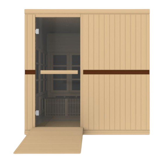
- Page 18 GDI-6880-02 – DIMENSIONAL DIAGRAM (cont’d) *Ramp is Optional *THE PICTURES AND DIAGRAMS SHOWN WITHIN THIS OWNER’S MANUAL ARE REPRESENTATIONS OF THIS MODEL. ACTUAL MODEL MAY VARY. DESIGN AND CONSTRUCTION ARE SUBJECT TO CHANGE.
-
Page 19: Screw Identification And Location Chart
SCREW IDENTIFICATION AND LOCATION CHART GDI-6880-02 *THE PICTURES AND DIAGRAMS SHOWN WITHIN THIS OWNER’S MANUAL ARE REPRESENTATIONS OF THIS MODEL. ACTUAL MODEL MAY VARY. DESIGN AND CONSTRUCTION ARE SUBJECT TO CHANGE. -
Page 20: Highlights
Highlights A. High quality craftsmanship B. Temperature control C. Timer D. Infrared carbon heat emitter panels E. Control Panel: F. Power supply: G. MP3 Jack:... - Page 21 H. Buckles: Guide and Guide Insert Brackets: J. Panel Descriptions: For easier assembly, please understand and distinguish the differences between each panel. Floor Panel When the FLOOR PANEL faces upward, you will find the floor heat emitter(s) on the topside of the FLOOR PANEL. (see Figure 1) Figure 1 Front Understanding the Difference Between the Top and Bottom of...
- Page 22 Heat Emitter Cords Figure 2 Rear Panel The REAR PANEL is the panel with the buckles. The buckles are mounted on the exterior side of the REAR PANEL. (see Figure 3) Figure 3 Understanding the Difference Between the Inside and Outside of the Wall Panels You will find the heat emitters on the inside of the wall panels.
-
Page 23: Assembly Instructions
Assembly Instructions 1. Choose a good location to assembly the sauna The location must be dry, level, and away from any source of water. The dedicated outlet must be easily accessible. Two adults will be needed to assemble. Wood Cabin Assembly: FLOOR PANEL RIGHT SIDE PANELS REAR WALL PANELS... -
Page 24: Side Panels
Installing the RIGHT SIDE PANELS a. One adult will need to place the first of the two RIGHT SIDE PANELS up and onto the FLOOR PANEL. Please take note of the trim molding on the FLOOR PANEL that will insert into the bottom of the wall panels. See Figure 6. - Page 25 Figure 8 Installing the REAR WALL PANELS While one adult holds the RIGHT SIDE PANELS in place, a second adult will need to place the first of the two REAR WALL PANELS up and onto the FLOOR PANEL. Again, note the trim molding on the FLOOR PANEL that will insert into the bottom of the wall panels.
- Page 26 Side Panel Rear Panel Figure 9 Figure 10 Figure 11 5. Installing the LEFT SIDE PANELS a. Place the first of the two LEFT SIDE PANELS up and onto the FLOOR PANEL. Again, note the trim molding on the FLOOR PANEL that will insert into the bottom of the wall panels.
- Page 27 Figure 12 Figure 13 6. Installing the FRONT WALL PANELS a. Place the FRONT WALL PANEL with the glass door up and onto the FLOOR PANEL. Again, note the trim molding on the FLOOR PANEL that will insert into the bottom of the wall panels. The FRONT WALL PANEL will need to be placed up against the LEFT SIDE PANEL.
- Page 28 7. Placing the removable BENCHES Inside the Sauna a. This model sauna is also designed for yoga. If yoga is to be performed within the sauna room, the benches should not be installed. In addition and if a yoga floor mat is to be used, do not connect the cords for the floor heat emitters.
- Page 29 Ceiling Vent Power Supply Figure 17 Front of Sauna Figure 18 Harness & Speaker Connections Figure 19 Connect All (6) Of The Heater Cord Connections...
- Page 30 Figure 20 Figure 21 9. Installing the TEMPERATURE SENSOR a. Enter the sauna and remove the protective covering (tape) from the TEMPERATURE SENSOR. Situate the TEMPERATURE SENSOR so that it is vertical, pointing downward. (see Figure 21) Figure 21 10. Installing the ROOF COVER a.
- Page 31 Figure 22 11. Installing the Ramp (optional and can be purchased separately) a. The optional wheelchair ramp can be placed in front of the door of the sauna. It must be placed close and butted up against the exterior side of the FRONT WALL PANEL.
-
Page 32: Operating The Sauna
CAUTION: Exit Sauna Immediately If You Feel Dizzy, Sleepy, Or Any Discomfort. Operating the Sauna NOTE: Please check and confirm that the connections to the POWER SUPPLY, HEAT EMITTERS, and TEMPERATURE SENSOR are connected properly. The power supply voltage and frequency must match the requested voltage and frequency of the sauna (120VAC 15AMP Dedicated Circuit or 120VAC 20AMP Dedicated Circuit). - Page 33 Status. You will see “Hello” on the display and you can now enter the main control interface mode within (3) seconds. If you press the “Power Off”, the system will enter the shutdown mode. If you press the “OK” button, the system will disable all functions. B.
- Page 34 1. Press the “ “ button to turn ON/OFF the interior Reading Light. a. Press each individual color buttons to select that color lighting. b. Press the “ “ button and the color light will go through a sequence of colors. 2.
- Page 35 adjust the volume (“ “). H. You can press the “ “ to return back to the main interface mode. I. Drink water prior to, during, and after your sauna session to replenish body fluids. J. After 3 hours of continuous use, the sauna needs to be shut down for one hour.
-
Page 36: Tips For Using Your Sauna
degrees C, the heat emitters will turn off when that set temperature is reached. And even though the sauna does allow the user to set the Control Panel to 151 degrees F/66 degrees C, this is specifically for those users who do not want the heat emitters to ever turn off as the sauna room will never achieve 151 degrees F / 66 degrees C. -
Page 37: Safety Instructions
towel to drape over your legs to trap the heat. 5. This is a non-commercial sauna. For every three hours ON, the sauna must be turned OFF for one hour to cool down. 6. At the first sign of a cold or flu, increasing your sauna sessions may be beneficial in boosting your immune system and decreasing the reproductive rate of the virus. - Page 38 recommended. 7. The use of alcohol, drugs, or medications (prescribed or non-prescribed) prior to or during the sauna session may lead to unconsciousness and/or other harmful physical injuries. 8. Persons suffering from obesity or with a medical history of heart disease, low or high blood pressure, circulatory system problems, diabetes, or other medical conditions should consult with a medical physician prior to using the sauna.
-
Page 39: Safeguards For Your Sauna
22. Do not pour water or any other liquids onto the infrared heat emitters. Do not bump, hit, or break the heating elements as it may cause an electrical short and pose a safety risk. 23. Do not make any modifications to the sauna, the sauna structure, or the sauna components. - Page 40 Solution: If the heat emitters are not working but the control panel displays the time and temperature, then the temperature sensor may not be plugged in properly or it may be damaged. Turn the control panel off and then go to the roof of the sauna and locate the red and black wires near the air vent towards the rear of the sauna.
-
Page 41: Maintenance
connections. Attempt to turn the sauna on at the control panel. Contact the manufacturer for any additional troubleshooting. Solution: There could be damage to the temperature sensor. If your sauna arrived with a spare temperature sensor, turn the control panel off and go to the roof of the sauna and locate the red and black wire near the air vent towards the rear of the sauna. -
Page 42: Warranty
Limited Lifetime Warranty 5 Year Limited Warranty*: Golden Designs, Inc. under the Dynamic brand name warranties the wood, structure, heating elements, and electronics against defects in material and workmanship for a period of 1 to 5 years from the original date of purchase. - Page 43 ▪ Outdoor applications ▪ Normal wear and tear or weathering ▪ Use of product not in accordance with instructions ▪ Worn out receptacle Surface cracks are not considered defects in material or workmanship, as they are normal characteristics of all woods. This includes minor cracks due to wood expansion and contraction.
- Page 44 PAGE INTENTIONALLY LEFT BLANK...
-
Page 45: Warranty Card
WARRANTY CARD Congratulations on your purchase of an Infrared Sauna from Golden Designs, Inc. Please take the time to complete the following Warranty Card and mail it back to: Golden Designs, Inc. 3550 Jurupa Street, Unit B Ontario, CA 91761 Please include a copy of your sales receipt showing date of purchase as this will serve as proof of purchase.
Need help?
Do you have a question about the GDI-6880-02 and is the answer not in the manual?
Questions and answers