Table of Contents
Advertisement
Quick Links
P.O. BOX 557 204 INDUSTRIAL PARK DRIVE
LAKEFIELD, MINNESOTA USA 56150-0577
READ ALL THESE STEPS BEFORE STARTING INSTALLATION. LEAVE THESE INSTRUCTIONS WITH THE APPLIANCE.
This kit must be installed by a qualified installer, service agency, or gas supplier at the time of the heater installation.
These instructions must be used in conjunction with the installation and operation manual provided with the appliance.
Please read all appliance owner's manual completely before performing any procedures in these instructions.
1.0 Introduction ............................................................. 3
1.1 Kit Contents ............................................................. 3
1.2 Suggest Configurations ............................................ 4
1.3 Dimensions and Overview ....................................... 5
1.4 Air Duct Run ............................................................. 5
2.0 Framing and Clearances ........................................... 6
2.1 Clearance to Sprinkler & Ceiling .............................. 6
2.2 Plenum Framing ...................................................... 7
2.3 Enclosure Framing ................................................. 10
3.0 Facing and Finishing ............................................... 13
3.1 Non-combustible Requirements ........................... 13
3.2 Finishing Requirements ......................................... 17
3.3 Hearth and Mantel Clearances .............................. 22
4.0 Fireplace Preparation & Installation ....................... 26
4.1 Nordik 48TL ........................................................... 26
4.2 Nordik 60TL ........................................................... 28
This optional convection duct kit redistributes the warm air flow away from the fireplace opening to a more desirable
location using natural convection without the use of a fan. The warm air flow would be relocated to a position higher up the
wall. The result is much cooler wall temperatures above the fireplace opening for locating televisions, artwork, etc.
KZK-062
Komfort Zone Kit #KZK-062
For use with Nordik 48 TL (#NDK-48TL) & Nordik 60TL
(#NDK-60-TL)
English and French installation manuals are available
through your local dealer. Visit our website
Les manuels d'installation en français et en anglais sont
disponibles chez votre détaillant local. Visitez
INSTALLER: Leave this manual with the appliance.
CONSUMER: Retain this manual for future reference.
IMPORTANT: Failure to read and follow these instructions
may create a possible hazard and will void the fireplace
1
www.kozyheat.com.
www.kozyheat.com.
warranty.
Rev. 2 - July 2024
Advertisement
Table of Contents

Subscribe to Our Youtube Channel
Related Manuals for kozy heat KZK-062


Summary of Contents for kozy heat KZK-062
-
Page 1: Table Of Contents
Komfort Zone Kit #KZK-062 For use with Nordik 48 TL (#NDK-48TL) & Nordik 60TL (#NDK-60-TL) P.O. BOX 557 204 INDUSTRIAL PARK DRIVE LAKEFIELD, MINNESOTA USA 56150-0577 READ ALL THESE STEPS BEFORE STARTING INSTALLATION. LEAVE THESE INSTRUCTIONS WITH THE APPLIANCE. This kit must be installed by a qualified installer, service agency, or gas supplier at the time of the heater installation. - Page 2 KZK-062 Rev. 2 - July 2024...
-
Page 3: Introduction
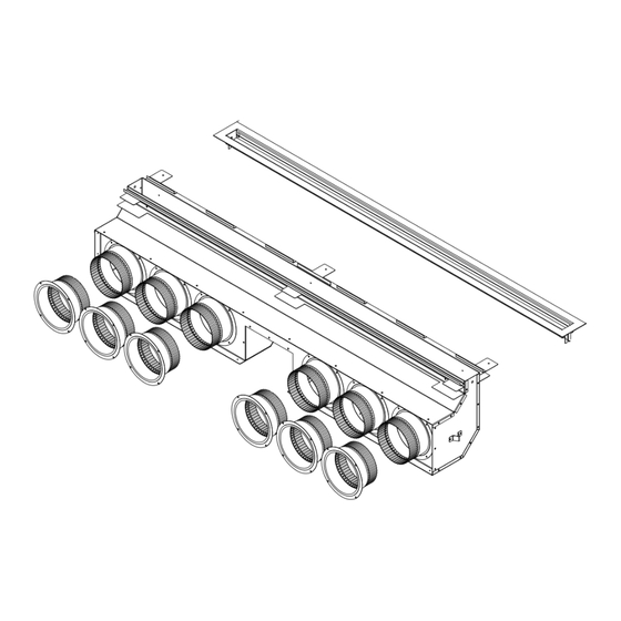
1.0 Introduction 1.1 Kit Contents ALL kit contents must be installed. • (1) 62" plenum kit: KZK-062 • (1) plenum discharge trim: KZK-062DT • (2) plenum support brackets • (12) 6" collars - (6) to attach to the bottom of the plenum;... -
Page 4: Suggest Configurations
When installing the #KZK-062, take in consideration the fireplace venting and the plenum tube configuration. • The #KZK-062 plenum must be installed so it discharges heat into the room the Nordik 48TL or Nordik 60TL is installed in. Nordik 48TL Figure 1.3 - Nordik 48TL Suggested Plenum Configurations... -
Page 5: Dimensions And Overview
1.3 Dimensions and Overview Figure 1.4 - KZK-062 Dimensions 1.4 Air Duct Run IMPORTANT: The air duct pipe cannot run horizontally without a vertical rise. IMPORTANT: The 1/2" clearance around the air duct pipes must be maintained. Use #KZK-610 UL181 Class 0 Air Duct piping to connect the plenum(s) to the unit. -
Page 6: Framing And Clearances
• Please follow local building codes to determine what temperature setting is relevant for your installation. Figure 2.1 - Clearance to Sprinkler KZK-062 Rev. 2 - July 2024... -
Page 7: Plenum Framing
Rough opening framing dimensions should allow for wall covering thickness and facing materials. Please refer to Section 3.0 for specific facing and finishing options. Figure 2.2 shows the framing dimensions for the plenum opening. Nominal 2”x4” framing used in interior enclosure framing. Figure 2.2 - Plenum Framing KZK-062 Rev. 2 - July 2024... - Page 8 The minimum height of plenum framing from the base is shown in Figure 2.3 for the Nordik 48TL. Nominal 2”x4” framing used in interior enclosure framing. Nordik 48TL Figure 2.3 - Nordik 48TL Plenum Framing KZK-062 Rev. 2 - July 2024...
- Page 9 The minimum height of plenum framing from the base is shown in Figure 2.4 for the Nordik 60TL. Nominal 2”x4” framing used in interior enclosure framing. Nordik 60TL Figure 2.4 - Nordik 60TL Plenum Framing KZK-062 Rev. 2 - July 2024...
-
Page 10: Enclosure Framing
TV pocket from the base of the fireplace. The allowed TV recess of 4-1/4” (108mm) measures from the front of the nominal 2x4 framing to the backside of the finishing material of the pocket. Nordik 48TL Figure 2.5 - Nordik 48TL Plenum Framing KZK-062 Rev. 2 - July 2024... - Page 11 TV pocket from the base of the fireplace. The allowed TV recess of 4-1/4” (108mm) measures from the front of the nominal 2x4 framing to the backside of the finishing material of the pocket. Nordik 60TL Figure 2.6 - Nordik 60TL Plenum Framing KZK-062 Rev. 2 - July 2024...
- Page 12 Note: The image below is of the Nordik 48TL but the dimensions for the TV pocket is applicable to both the Nordik 48TL and Nordik 60TL. Nordik 48TL & 60TL Nominal 2”x4” framing used in interior enclosure framing Figure 2.7 - TV Recessed Cavity Top Framing Clearance KZK-062 Rev. 2 - July 2024...
-
Page 13: Facing And Finishing
3.0 Facing and Finishing 3.1 Non-Combustible Requirements Nordik 48TL Figure 3.1 - Nordik 48TL Minimum Non-Combustible Finishing Dimensions KZK-062 Rev. 2 - July 2024... - Page 14 Nordik 60TL Figure 3.2 - Nordik 60TL Minimum Non-Combustible Finishing Dimensions KZK-062 Rev. 2 - July 2024...
- Page 15 Figure 3.3 shows the location where no screws are allowed in the combustible or non-combustible finishing material. Nordik 48TL Figure 3.3 - Nordik 48TL - No Screw Location KZK-062 Rev. 2 - July 2024...
- Page 16 Figure 3.4 shows the location where no screws are allowed in the combustible or non-combustible finishing material. Nordik 60TL Figure 3.4 - Nordik 60TL - No Screw Location KZK-062 Rev. 2 - July 2024...
-
Page 17: Finishing Requirements
See Figure 3.5 for finishing options. Finishing material must not block the opening and must be run evenly along the plenum opening. WARNING! RISK OF OVERHEATING AND FIRE! Ensure the KZK duct system is installed in accordance to this manual Figure 3.5 - Plenum Air Discharge Finishing Options KZK-062 Rev. 2 - July 2024... - Page 18 This 1" (25mm) combustible material is able to go down to the fireplace finishing edge. • See Figure 3.5 (center image) for up to 1" (25mm) thick combustible material installation around the KZK air discharge trim. Nordik 48TL Figure 3.6 - Nordik 48TL Combustible Wall Finish KZK-062 Rev. 2 - July 2024...
- Page 19 This 1" (25mm) combustible material is able to go down to the fireplace finishing edge. • See Figure 3.5 (center image) for up to 1" (25mm) thick combustible material installation around the KZK air discharge trim. Nordik 60TL Figure 3.7 - Nordik 60TL Combustible Wall Finish KZK-062 Rev. 2 - July 2024...
- Page 20 1” combustible wall finish is required to go on top of any noncombustible finishing material requirements outlined in this manual. See Figure 3.1 and 3.2. Nordik 48TL & 60TL Figure 3.8 - Front View of Combustible Wall Finish KZK-062 Rev. 2 - July 2024...
- Page 21 For a painted surface, use a high quality acrylic latex primer and finish coat. Avoid flat or light-colored paints to prevent discoloring. Disclaimer: Kozy Heat does not guarantee any materials used around the fireplace. Kozy Heat disclaims any and all liability for any damage to finishing materials including warping, discoloring, cracking, peeling or flaking. This also includes any off- gassing or unpleasant smells from materials when they are heated.
-
Page 22: Hearth And Mantel Clearances
• Combustible Sidewall Clearance: The adjacent sidewall projection is unlimited and starts at 6” (152mm) from the side of the fireplace. See Figure 3.10. Figure 3.9 - Nordik 48TL Combustible Hearth and Mantel Requirements KZK-062 Rev. 2 - July 2024... - Page 23 This places the sidewall flush with the KZK plenum opening. If you are using the KZK discharge trim provide an extra 1/2” clearance so your sidewall would be located 6-1/2 (165mm) away from the side fireplace finishing edge. Figure 3.10 - Nordik 48TL Combustible Sidewall Requirements KZK-062 Rev. 2 - July 2024...
- Page 24 • Combustible Sidewall Clearance: The adjacent sidewall projection is unlimited and starts at 0” (0mm) from the side of the fireplace. See Figure 3.12. Figure 3.11 - Nordik 60TL Combustible Hearth and Mantel Requirements KZK-062 Rev. 2 - July 2024...
- Page 25 The sidewall would be located 3/4” (19mm) away from the side fireplace finishing edge. This would provide clearance for both the KZK discharge trim and the fireplace rectangle surround. Figure 3.12 - Nordik 60TL Combustible Sidewall Requirements KZK-062 Rev. 2 - July 2024...
-
Page 26: Fireplace Preparation & Installation
Discard the screws and convection baffles. 4. Frame the rough opening of the fireplace and KZK plenum. Refer to all pages of this KZK-062 manual and the Nordik 48TL manual. See previous pages of this manual for allowable plenum positions and rough frame opening sizes. - Page 27 If desired, the air grille may be painted. Use high temperature paint (250°F). Continue with fireplace installation. Figure 4.5 - Nordik 48TL Stand-Off Installation Figure 4.6 - Trim Installation Figure 4.4 - Nordik 48TL Air Flow with Cover Plates Removed KZK-062 Rev. 2 - July 2024...
-
Page 28: Nordik 60Tl
Discard the screws and convection baffles. 4. Frame the rough opening of the fireplace and KZK plenum. Refer to all pages of this KZK-062 manual and the Nordik 60TL manual. See previous pages of this manual for allowable plenum positions and rough frame opening sizes. - Page 29 If desired, the air grille may be painted. Use high temperature paint (250°F). Continue with fireplace installation. Figure 4.11 - Nordik 60TL Stand-Off Installation Figure 4.12 - Trim Installation Figure 4.10 - Nordik 60TL Air Flow with Cover Plates Removed KZK-062 Rev. 2 - July 2024...
Need help?
Do you have a question about the KZK-062 and is the answer not in the manual?
Questions and answers