
Subscribe to Our Youtube Channel
Related Manuals for Lenze MC Series


Summary of Contents for Lenze MC Series
- Page 1 BA 33.0006−EN .@KL Operating Instructions MC., MQA, MD... MCA, MCS, MQA, MD KS, MDFQA Asynchronous servo motors, synchronous servo motors...
- Page 2 Please read these instructions before you start working! Follow the enclosed safety instructions. Detailed information is given in the corresponding operating instructions. 0Fig. 0Tab. 0 BA 33.0006−EN 1.0...
-
Page 3: Table Of Contents
Contents About this documentation ..........Document history . - Page 4 Contents Terminal box ............6.4.1 Motor .
-
Page 5: About This Documentation
If the information and notes provided in this documentation do not meet your requirements, please refer to the controller and/or gearbox documentation. Tip! Documentation and software updates for further Lenze products can be found on the Internet in the "Services & Downloads" area under http://www.Lenze.com... -
Page 6: Conventions Used
Servo motor in the versions according to the product key, see page 16 to page 18 . Controller Any servo inverter Any frequency inverter Drive system Drive systems with servo motors and with other Lenze drive components BA 33.0006−EN 1.0... -
Page 7: Notes Used
About this documentation Notes used Notes used The following pictographs and signal words are used in this documentation to indicate dangers and important information: Safety instructions Structure of safety instructions: Danger! (characterises the type and severity of danger) Note (describes the danger and gives information about how to prevent dangerous situations) Pictograph and signal word Meaning... -
Page 8: Safety Instructions
At the time of dispatch, the drive components are in line with the latest state of the art and can be regarded as operationally safe. Scope The following safety instructions generally apply to Lenze drive system components. Be absolutely sure to observe the product−specific safety and application notes given in this documentation! - Page 9 – This is the prerequisite for safe and trouble−free operation and achieving the specified product features. Only qualified personnel may work with and on Lenze drive components. ƒ According to IEC 364 and CENELEC HD 384, these are persons ...
- Page 10 Safety instructions General safety instructions for drive components Transport, storage Transport and storage in a dry, low−vibration environment without aggressive ƒ atmosphere; preferably in the packaging provided by the manufacturer. – Protect against dust and shocks – Comply with climatic conditions according to the technical data. Before transport ƒ...
-
Page 11: Application As Directed
Safety instructions Application as directed Operation Keep all protective covers and doors closed during operation. ƒ Application as directed Low−voltage machines are no household appliances, they are designed as components for industrial or professional use in terms of IEC/EN 61000−3−2 only. They comply with the harmonised standards of the series IEC/EN 60034. -
Page 12: Residual Hazards
Safety instructions Residual hazards Residual hazards Protection of persons Do not use the integrated brakes as fail−safe brakes. It cannot be ruled out that ƒ certain disruptive factors that cannot be influenced such as oil ingress due to a defective shaft sealing ring at the drive end may reduce the braking torque. Motor protection Integrated temperature sensors do not provide full protection for the machine. -
Page 13: Product Description
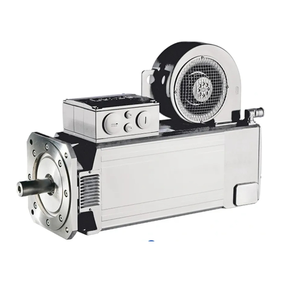
Product description Identification Product description Identification Types MC., MQA Synchronous servo motors Asynchronous servo motors MT−MCS−001.iso MT−MCA−001.iso MT−MQA−001.iso Type MD... Asynchronous servo motors Synchronous servo motors MDFQA MDLKS MT−MDFQA−002.iso MT−MDFKS−001.iso BA 33.0006−EN... -
Page 14: Identification Nameplate
Product description Identification Nameplate 3.1.1 Nameplate Asynchronous and synchronous servo motors Nameplate SYN−001.iso IP23 MDFQA asynchronous servo motors Nameplate−SYN−002.iso BA 33.0006−EN 1.0... - Page 15 Product description Identification Nameplate Explanation Manufacturer Motor type Lenze motor type Rated voltage U Rated current I Maximum current I Designation of encoder/resolver compensation value ... Data for holding brake: voltage, current, torque Motor No. Degree of protection Thermal class Rated ambient temperature 8−digit identification number + 16−digit serial number...
-
Page 16: Product Key
Product description Identification Product key 3.1.2 Product key Servo motors MCA, MCS, MQA − − − − Legend for product key 0 Type Compact servo motors (if required, with axial ventilation) Radially ventilated motor 1 Design Asynchronous Synchronous 2 Motor frame size, motor length, speed Square dimension 62 mm Square dimension 192 mm Square dimension 89 mm... - Page 17 Product description Identification Product key 4 Brake Without brake Spring−applied brake 230V DC, reinforced Spring−applied brake 24V DC PM brake 24V DC Spring−applied brake 24V DC, reinforced PM brake 24V DC, reinforced Spring−applied brake 205V DC PM brake 205V DC Spring−applied brake 205V DC, reinforced PM brake 205V DC, reinforced Spring−applied brake 230V DC...
- Page 18 Product description Identification Product key Servo motors MDLLL − Legend for type code Type Three−phase AC current Cooling method, ventilation Forced ventilated Natural ventilation (cooling by convection and radiation) Design, housing Compact servo motor with square housing and cooling ribs IP23 servo motor with square housing Machine type Asynchronous machine...
-
Page 19: Technical Data
Technical data General data and operating conditions Technical data General data and operating conditions General data Conformity and approval Conformity 2006/95/EC Low−Voltage Directive Approvals UL / CSA File no. E210321 MCA, MCS, MQA; optionally MDFQA, MDLKS Protection of persons and equipment Degree of protection See nameplate Degrees of protection only apply to horizontal installation... -
Page 20: Holding Brake (Option)
Average relative humidity 85 %, without condensation Electrical The motor connection type depends on the controller Length of motor < 20 m (Lenze system cable, shielded) cable Length of cable for < 20 m (Lenze system cable, shielded) speed feedback... - Page 21 Technical data Holding brake (option) Important notes The following applies to Lenze system cables: U* [V] Resulting supply voltage ) 0.08 V U * + U @ l @ I m @ A [V] Rated voltage of the brake l [m]...
-
Page 22: Permanent Magnet Holding Brakes
Technical data Holding brake (option) Permanent magnet holding brakes 4.2.2 Permanent magnet holding brakes These brakes are used as holding brakes and serve to hold the axes without backlash at standstill or in the deenergised state. When activating the brake, it must be ensured that the brake is released or engaged at zero speed to avoid unnecessary and rapid wear of the brake. -
Page 23: Spring−Applied Holding Brakes
Technical data Holding brake (option) Spring−applied holding brakes 4.2.3 Spring−applied holding brakes These brakes are used as holding brakes and serve to hold the axes without backlash at standstill or in the deenergised state. For permissible operating speeds and characteristics, please see catalogue for spring−applied brakes. - Page 24 Technical data Holding brake (option) Spring−applied holding brakes Component Cause Effect Influencing factors Friction lining Emergency stops Wear on the Applied friction energy friction lining Overlapping wear when the drive starts and stops Active braking by the drive motor with the help of the brake (quick stop) Starting wear if motor is mounted Number of start−stop...
-
Page 25: Mechanical Installation
Mechanical installation Preparation Mechanical installation Preparation Remove the corrosion protection from the shaft ends and flanges. If necessary, remove dirt using standard cleaning solvents. Stop! Bearings or seals must not come into contact with the solvent − material damages. After a long storage period (> 1 year) you have to check whether moisture has entered the motor. -
Page 26: Installation
Mechanical installation Installation Installation The mounting surface must be dimensioned for the design, weight and torque of ƒ the motor. The foot and flange faces must rest flat on the mounting surface. ƒ – Incorrect motor alignment reduces the service life of the roller bearings and transmission elements. -
Page 27: Electrical Installation
Electrical installation Important notes Electrical installation Important notes Danger! Hazardous voltage on the power connections even when disconnected from mains: residual voltage >60 V! Before working on the power connections, always disconnect the drive component from the mains and wait until the motor is at standstill. Verify safe isolation from supply! Stop! Electrical connections must be carried out in accordance with the national and... -
Page 28: Wiring According To Emc
Wiring according to EMC Wiring according to EMC The EMC−compliant wiring of the motors is described in detail in the Operating Instructions for the Lenze controllers. Use of metal EMC cable glands with shield connection. ƒ Connect the shielding to the motor and to the device. -
Page 29: Ac/Dc Holding Brake (Optional)
AC/DC holding brake (optional) 6.3.2 AC/DC holding brake (optional) MCA, MCS, MQA (external view of poles) Meaning M40 (size 1.5) Standard/Lenze designation MCA 19...20, MCS 14...19, MQA 20 Not assigned BD1 / BA1 Holding brake + / ~ − BD2 / BA2 Holding brake −... -
Page 30: Fan
Electrical installation Plug connectors 6.3.3 MCA, MCS, MQA (external view of poles) Meaning Single−phase PE conductor Not assigned MQA (external view of poles) Meaning Three−phase PE conductor Not assigned Not assigned MDLKS 056 ... 112 (external view of poles) Meaning Single−phase PE conductor Not assigned... -
Page 31: Feedback System
Electrical installation Plug connectors Feedback system 6.3.4 Feedback system Resolver (external view of poles) Meaning M23 (size 1.0) + Ref Transformer windings − Ref (reference windings) +VCC ENP Supply: electronic nameplate + Cos Stator windings cosine − Cos + Sin Stator windings sine −... -
Page 32: Terminal Box
Electrical installation Terminal box Feedback system Terminal box MCS; MLA 20 MLA 22...26; MDFQA MT−terminal−box−001.iso MT−terminal−box−002.iso The openings in the terminal box are cast closed and can be opened by the customer as required. MCA 10...17; MDLKS 056...071 MCA 19, 21 MT−terminal−box−003.iso MT−terminal−box−004.iso BA 33.0006−EN 1.0... -
Page 33: Motor
Electrical installation Terminal box Motor 6.4.1 Motor MCA; MCS, MQA, MDLKS Terminal Meaning Standard/Lenze designation PE conductor for motor housing Motor winding phase U Motor winding phase V Motor winding phase W TP1 (P1) PTC thermistor TP2 (P2) TB1 (S1) -
Page 34: Ac Holding Brake (Optional)
BA2 / ~ (2/Y2) Connection to brake, + Factory−wired − Connection to brake, − Switching contact, DC switching 6.4.3 DC holding brake (optional) Terminal Meaning Standard/Lenze designation BD1 (Y1) Connection to DC + Connection to DC − BD2 (Y2) BA 33.0006−EN 1.0... -
Page 35: Fan
Electrical installation Terminal box 6.4.4 MCA, MQA, MDLKL − single−phase Terminal Meaning PE conductor L1 / U1 Connection to L1 − mains N / U2 Connection to N − mains MQA, MDFQA − three−phase Terminal Meaning PE conductor Screwed connections Motor type/size Screwed connection MCA/MQA... -
Page 36: Feedback System
Electrical installation Terminal box Feedback system 6.4.5 Feedback system Sin−cos absolute value encoder with EnDat interface Terminal Meaning +5 V Supply +5 V / +VCC ENP Supply 0 V / earth Track A / + cos Track A inverse / − cos Track B / +sin Track B inverse / −sin Data... - Page 37 Electrical installation Terminal box Feedback system Sin−cos absolute value encoder with EnDat interface Terminal Meaning +5 V Supply +5 V / +VCC ENP Supply 0 V / earth Track A / + cos Track A inverse / − cos Track B / +sin Track B inverse / −sin Data Data EnDat interface...
-
Page 38: Commissioning And Operation
Before switching on the motor, it is absolutely necessary to make sure that the motor starts in the intended direction of rotation. The Lenze motors are designed such that the motor rotates CCW when viewed on the fan cover when a CW three−phase field L1 W U1, L2 WV1, L3 W W1 is applied. -
Page 39: Functional Test
Commissioning and operation Functional test Functional test Functional test Check all functions of the drive after commissioning: ƒ Direction of rotation of the motor ƒ – Direction of rotation in the disengaged state (see chapter "Electrical connection"). Torque behaviour and current consumption ƒ... -
Page 40: Maintenance & Repair
Maintenance/repair Important notes Maintenance/repair Important notes Danger! Hazardous voltage on the power connections even when disconnected from mains: residual voltage >60 V! Before working on the power connections, always disconnect the drive component from the mains and wait until the motor is at standstill. Verify safe isolation from supply! Shaft sealing rings and roller bearings have a limited service life. -
Page 41: Holding Brake
Hot motor surfaces up to 140 °C. Observe cooling times! ƒ Remove loads acting on motors or secure loads acting on the drive! ƒ 8.3.1 Holding brake The brake is not accessible! Maintenance work on the brake may only be carried out by Lenze Service staff! BA 33.0006−EN... -
Page 42: Blower
For motors equipped with a dry filter, the dust must be shaken out completely. If the dust is wet, the filter mat must be replaced. Repair It is recommended to have all repairs performed by Lenze Service. ƒ Delivery of spare parts is available upon request. -
Page 43: Troubleshooting And Fault Elimination
Also observe the corresponding chapters in the operating instructions for the other ƒ components of the drive system. If the fault cannot be remedied using one of the listed measures, please contact the Lenze Service. Danger! Esure that the drive system is deenergised before working on it! ƒ... - Page 44 Troubleshooting and fault elimination Fault Cause Remedy Motor rotates normally Motor cable interchanged cyclically Connect the phases at the motor cable connection correctly but does not generates the expected torque Motor rotates in one Motor cable interchanged cyclically Check motor connection and, if necessary, correct it direction at maximum speed in an uncontrolled Polarity of encoder cable reversed...
- Page 45 Notes BA 33.0006−EN...
- Page 46 Notes BA 33.0006−EN 1.0...
- Page 47 Notes BA 33.0006−EN...
- Page 48 © 07/2009 Lenze Drives GmbH Service Lenze Service GmbH Postfach 10 13 52 Breslauer Straße 3 D−31763 Hameln D−32699 Extertal Germany Germany +49 (0)51 54 / 82−0 00 80 00 / 24 4 68 77 (24 h helpline) Ê Ê...
Need help?
Do you have a question about the MC Series and is the answer not in the manual?
Questions and answers