Sign In
Upload
Download
Table of Contents
Contents
Add to my manuals
Delete from my manuals
Share
URL of this page:
HTML Link:
Bookmark this page
Add
Manual will be automatically added to "My Manuals"
Print this page
×
Bookmark added
×
Added to my manuals
Manuals
Brands
Lenze Manuals
Engine
MCS 06C60
Mounting and switch-on instructions
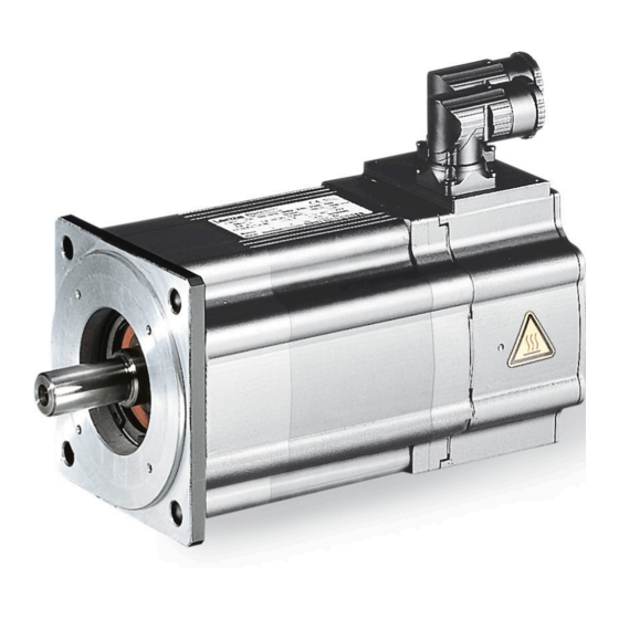
Lenze MCS 06C60 Mounting And Switch-On Instructions
Synchronous servo motor
Hide thumbs
1
2
Table Of Contents
3
4
5
6
7
8
9
10
11
12
13
14
15
16
17
18
19
20
21
22
23
24
25
26
27
28
29
30
31
32
33
34
35
36
37
38
39
40
41
42
43
44
45
46
47
48
49
50
51
52
page
of
52
Go
/
52
Contents
Table of Contents
Bookmarks
Table of Contents
Table of Contents
About this Document
Document Description
Further Documents
Notations and Conventions
Safety Instructions
Basic Safety Instructions
Application as Directed
Foreseeable Misuse
Residual Hazards
Product Information
Identification of the Products
Nameplates
Product Codes
Equipment
Transport
Storage
Mechanical Installation
Important Notes
Preparation
Installation
Dimensions
Mounting
Electrical Installation
Important Notes
Preparation
Motor Connection
Connection Via Terminal Box
Connection Via ICN Connector
Commissioning
Important Notes
Before Initial Switch-On
Functional Test
Maintenance
Repair
Diagnostics and Fault Elimination
Malfunctions
Technical Data
Standards and Operating Conditions
Conformity and Approvals
Protection of Persons and Device Protection
EMC Data
Environmental Conditions
Rated Data
Inverter Power Supply 400 V, Self-Ventilated Motors
Inverter Power Supply 400 V, Forced Ventilated Motors
Inverter Power Supply 230 V, Self-Ventilated Motors
Environmental Notes and Recycling
Advertisement
Quick Links
1
Document Description
2
Electrical Installation
3
Motor Connection
4
Connection Via Icn Connector
5
Technical Data
Download this manual
Mounting and switch-on instructions EN
Servo motors
MCS synchronous servo motor
Table of
Contents
Previous
Page
Next
Page
1
2
3
4
5
Advertisement
Table of Contents
Need help?
Do you have a question about the MCS 06C60 and is the answer not in the manual?
Ask a question
Questions and answers
Related Manuals for Lenze MCS 06C60
Engine Lenze M Series Supplement To Operating Instructions
Asynchronous servo motors with spring-applied brake mounted on the b-bearing side (20 pages)
Engine Lenze MD KS Series Operating Instructions Manual
Asynchronous servo motors / synchronous servo motors (48 pages)
Engine Lenze M Series Operating Instructions Manual
Asynchronous servo motors / synchronous servo motors (46 pages)
Engine Lenze MCM Series Mounting And Switch-On Instructions
Synchronous servo motor (52 pages)
Engine Lenze M Series Mounting Instructions
Servo asynchronous motors; servo synchronous motors (37 pages)
Engine Lenze MCA Series Mounting And Switch-On Instructions
Asynchronous servo motors (80 pages)
Engine Lenze MCA 10I40 Series Mounting And Switch-On Instructions
Asynchronous servo motor (44 pages)
Engine Lenze MC Series Operating Instructions Manual
Asynchronous servo motors, synchronous servo motors (48 pages)
Engine Lenze MCS09 Mounting And Switch-On Instructions
Geared servo motors (68 pages)
Engine Lenze MCS 14H32 Series Operating Instructions Manual
Asynchronous servo motors / synchronous servo motors (46 pages)
Engine Lenze MCS 06C41 Mounting And Switch-On Instructions
Synchronous servo motor (52 pages)
Engine Lenze MCS 06F41 Mounting And Switch-On Instructions
Synchronous servo motor (52 pages)
Engine Lenze MCS 06I60 Mounting And Switch-On Instructions
Synchronous servo motor (52 pages)
Engine Lenze MCS 06I41 Mounting And Switch-On Instructions
Synchronous servo motor (52 pages)
Engine Lenze MCA Operating Instructions Manual
Asynchronous servo motors, synchronous servo motors (48 pages)
Engine Lenze MSEMAXX063-42 Project Planning
Mains-operated geared motors. helical geared motor / smart motor (104 pages)
This manual is also suitable for:
Mcs 06c41
Mcs 06f60
Mcs 06f41
Mcs 06i60
Mcs 06i41
Table of Contents
Print
Rename the bookmark
Delete bookmark?
Delete from my manuals?
Login
Sign In
OR
Sign in with Facebook
Sign in with Google
Upload manual
Upload from disk
Upload from URL


Need help?
Do you have a question about the MCS 06C60 and is the answer not in the manual?
Questions and answers