
Related Manuals for Acson international A5CM 20 E


Summary of Contents for Acson international A5CM 20 E
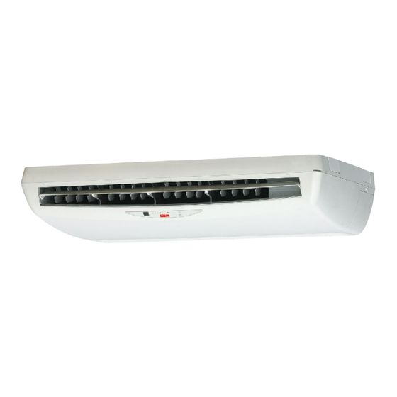
- Page 1 Models: A5CM 20 E/ER A5CM 25 E/ER A5CM 28 E/ER Ceiling Convertible Split Systems ACM - E- 2006...
-
Page 2: Table Of Contents
CONTENTS 1. NOMENECLATURE ....................1 2. FEATURES ........................ 3 3. PRODUCT LINE-UP ....................4 4. SPECIFICATIONS ..................... 7 5. OPERATING RANGE ....................32 6. PERFORMANCE TABLE ..................33 7. OUTLINES AND DIMENSIONS ................50 8. REFRIGERANT CIRCUIT DIAGRAMS ..............52 9. -
Page 3: Nomeneclature
1. NOMENCLATURE Indoor Others A : First issue Other Specifications I : Ionizer Generator N : Non Thermal Plasma Controller Specifications G : Wireless handset S : SLM3 N : Netware III Market Region C : Export with CE mark Electrical A : 220 - 240V/1Ph/50Hz Model Type... - Page 4 Outdoor Others A : First issue Air Treatment Devices & Control O : Standard unit I : Gold Fin B : With Contactor L : Long Piping Unit G : Low Ambient Unit S : With H/L Pressure Switch H : High ambient unit X :Oxygen Unit Contoller Type P : Matsushita Rotary...
-
Page 5: Features
2. FEATURES CEILING AND FLOOR INSTALLATION OPTION The unit is uniquely designed with the option to install either below the ceiling or mounted at low wall position without any modification needed. Furthermore, the unit is design adds a touch of elegance to suit any interior design requirement EXCELLENT AIR DISTRIBUTION The louver with automatic air swing function fully optimize the room comfort by enables the air flow to be... -
Page 6: Product Line-Up
3. PRODUCT LINE UP INDOOR UNIT ACM-E SERIES PRODUCT LINE UP Classification Handset ACGIA ACGNA ACGIA ACGNA ACGIA ACGNA ACGIA 20ER ACGNA ACGIA 25ER ACGNA ACGIA 28ER ACGNA A5CM-E SERIES PRODUCT LINE UP Classification Handset A5CM ACGIA ACGNA ACGIA ACGNA ACGIA ACGNA ACGIA... - Page 7 OUTDOOR UNIT A5LC-C SERIES PRODUCT LINE UP Classification Safety Devices A5LC ACPOA ACPOA ACPOA FCCOA 20CR ACPOA 25CR ACPOA 28CR ACPOA 35CR FCCOA...
- Page 8 General Data - Cooling Only (R410A) INDOOR UNIT A5CM 20E A5CM 25E MODEL OUTDOOR UNIT A5LC 20C A5LC 25C Btu/h 17500 20000 NOMINAL CAPACITY 5130 5860 NOMINAL TOTAL INPUT POWER 1723 1973 NOMINAL RUNNING CURRENT POWER SOURCE 220 - 240 / 1 / 50 V/Ph/Hz REFRIGERANT TYPE / CONTROL R410A / OUTDOOR CAP.
- Page 9 General Data - Cooling Only (R410A) INDOOR UNIT A5CM 28E MODEL OUTDOOR UNIT A5LC 28C A5LC 35C Btu/h 27000 30000 NOMINAL CAPACITY 7900 8790 NOMINAL TOTAL INPUT POWER 2754 2784 NOMINAL RUNNING CURRENT 13.0 POWER SOURCE 220 - 240 / 1 / 50 380 - 415 / 3 / 50 V/Ph/Hz REFRIGERANT TYPE / CONTROL...
- Page 10 General Data - Heatpump (R410A) INDOOR UNIT A5CM 20ER A5CM 25ER MODEL OUTDOOR UNIT A5LC 20CR A5LC 25CR Btu/h 17500 20000 NOMINAL COOLING CAPACITY 5130 5860 18500 22000 Btu/h NOMINAL HEATING CAPACITY 5420 6450 NOMINAL TOTAL INPUT POWER (COOLING) 1723 1973 NOMINAL TOTAL INPUT POWER (HEATING) 1493...
- Page 11 General Data - Heatpump (R410A) INDOOR UNIT A5CM 28ER MODEL OUTDOOR UNIT A5LC 28CR A5LC 35CR Btu/h 27000 30000 NOMINAL COOLING CAPACITY 7900 8790 27500 31000 Btu/h NOMINAL HEATING CAPACITY 8050 9090 NOMINAL TOTAL INPUT POWER (COOLING) 2754 2784 NOMINAL TOTAL INPUT POWER (HEATING) 2455 2634 NOMINAL RUNNING CURRENT (COOLING)
- Page 12 Electrical Data - Cooling Only (R410A) INDOOR UNIT A5CM 20E MODEL OUTDOOR UNIT A5LC 20C A5LC 25C INSULATION GRADE CLASS B 220 - 240 / 1 / 50 POWER SOURCE V/Ph/Hz RATED INPUT POWER INDOOR MOTOR RATED RUNNING CURRENT 0.46 0.49 MOTOR OUTPUT POLES...
- Page 13 Electrical Data - Heatpump (R410A) INDOOR UNIT A5CM 20ER A5CM 25ER MODEL OUTDOOR UNIT A5LC 20CR A5LC 25CR CLASS B INSULATION GRADE 220 - 240 / 1 / 50 POWER SOURCE V/Ph/Hz RATED INPUT POWER INDOOR MOTOR RATED RUNNING CURRENT 0.46 0.49 MOTOR OUTPUT...
- Page 14 Components Data (R410A) INDOOR UNIT A5CM 20E A5CM 25E MODEL OUTDOOR UNIT A5LC 20C A5LC 25C TYPE CROSS FLOW QUANTITY MATERIAL INDOOR FAN DRIVE DIRECT 146 / 5.75 DIAMETER mm/in LENGTH 200 / 7.87 mm/in TYPE INDUCTION INDOOR FAN QUANTITY MOTOR INDEX OF PROTECTION (IP) TYPE...
- Page 15 Components Data (R410A) INDOOR UNIT A5CM 28E MODEL OUTDOOR UNIT A5LC 28C A5LC 35C TYPE CROSS FLOW QUANTITY MATERIAL INDOOR FAN DRIVE DIRECT DIAMETER 146 / 5.75 mm/in 200 / 7.87 LENGTH mm/in TYPE INDUCTION INDOOR FAN QUANTITY MOTOR INDEX OF PROTECTION (IP) TYPE PROPELLER QUANTITY...
- Page 16 Components Data (R410A) INDOOR UNIT A5CM 20ER A5CM 25ER MODEL OUTDOOR UNIT A5LC 20CR A5LC 25CR TYPE CROSS FLOW QUANTITY MATERIAL INDOOR FAN DRIVE DIRECT 146 / 5.75 DIAMETER mm/in LENGTH 200 / 7.87 mm/in TYPE INDUCTION INDOOR FAN QUANTITY MOTOR INDEX OF PROTECTION (IP) TYPE...
- Page 17 Components Data (R410A) INDOOR UNIT A5CM 28ER MODEL OUTDOOR UNIT A5LC 28CR A5LC 35CR TYPE CROSS FLOW Q'TY MATERIAL INDOOR FAN DRIVE DIRECT DIAMETER 146 / 5.75 mm/in 200 / 7.87 LENGTH mm/in TYPE INDUCTION INDOOR FAN Q'TY MOTOR INDEX OF PROTECTION (IP) TYPE PROPELLER Q'TY...
-
Page 18: Safety Devices
Safety Devices INDOOR UNIT A5CM 20E A5CM 25E MODEL OUTDOOR UNIT A5LC 20C A5LC 25C TYPE HIGH PRESSURE SWITCH OPEN kPa / psi CLOSE kPa / psi TYPE SAFETY DEVICE LOW PRESSURE SWITCH OPEN kPa / psi CLOSE kPa / psi PHASE SEQUENCER DISCHARGE THERMOSTAT SETTING °C / °F... -
Page 19: Cooling Only
5. OPERATING RANGE Ensure the operating temperature is in allowable range. Cooling only High ambient unit Standard Caution : point The use of your air conditioner outside the range of working temperature and humidity can Low ambient kit result in serious failure. Indoor temp. -
Page 20: Performance Table
6. PERFORMANCE TABLE Interpolation and Extrapolation method can be used to get the total capacity, TC and sensible capacity, SC at those temperatures which are not stated out in the table. Example: Model: ACM 20E - ALC 20C Indoor Condition: 23°C DB, 15°C WB Outdoor Condition: 37°C DB Solution: Overall... - Page 21 Details: Step: To obtain the Total capacity and Sensible capacity for (a) Indoor Condition: 24°C DB, 15°C WB Outdoor Condition: 35°C DB Outdoor DB ° C Indoor DB Indoor WB ° C ° C TC (kW) SC (kW) 5.211 3.749 5.350 3.510 Total capacity, TC...
- Page 22 Step: To obtain the Total capacity and Sensible capacity for (a) Indoor Condition: 23°C DB, 15°C WB Outdoor Condition: 35°C DB Outdoor DB ° C Indoor DB Indoor WB ° C ° C TC (kW) SC (kW) 5.071 2.984 5.071 3.988 Total capacity, TC ⇒...
- Page 23 Step: To obtain the Total capacity and Sensible capacity for (a) Indoor Condition: 23°C DB, 15°C WB Outdoor Condition: 37°C DB Outdoor DB ° C Indoor DB Indoor WB ° C ° C TC (kW) SC (kW) TC (kW) SC (kW) TC (kW) SC (kW) 5.071...
- Page 24 R410A MODELS (COOLING ONLY) MODEL : A5CM 20E / A5LC 20C Outdoor DB°C ID DB°C ID WB°C TC(kW) SC(kW) TC(kW) SC(kW) TC(kW) SC(kW) TC(kW) SC(kW) TC(kW) SC(kW) TC(kW) SC(kW) 5.715 3.788 5.176 3.247 4.622 2.692 4.068 2.137 3.514 1.581 2.849 0.915 5.842 3.492...
- Page 25 R410A MODELS (COOLING ONLY) MODEL : A5CM 28E / A5LC 28C Outdoor DB°C ID DB°C ID WB°C TC(kW) SC(kW) TC(kW) SC(kW) TC(kW) SC(kW) TC(kW) SC(kW) TC(kW) SC(kW) TC(kW) SC(kW) 8.088 5.364 7.605 4.869 7.036 4.410 6.468 3.951 5.899 3.492 5.217 2.942 8.340 5.050...
- Page 26 R410A MODELS (HEATPUMP) MODEL : A5CM 20ER / A5LC 20CR COOLING MODE Outdoor DB°C ID DB°C ID WB°C TC(kW) SC(kW) TC(kW) SC(kW) TC(kW) SC(kW) TC(kW) SC(kW) TC(kW) SC(kW) TC(kW) SC(kW) 5.715 3.788 5.176 3.247 4.622 2.692 4.068 2.137 3.514 1.581 2.849 0.915 5.842...
- Page 27 R410A MODELS (HEATPUMP) MODEL : A5CM 25ER / A5LC 25CR COOLING MODE Outdoor DB°C ID DB°C ID WB°C TC(kW) SC(kW) TC(kW) SC(kW) TC(kW) SC(kW) TC(kW) SC(kW) TC(kW) SC(kW) TC(kW) SC(kW) 5.924 4.060 5.602 3.715 5.279 3.405 4.956 3.096 4.633 2.787 4.246 2.416 6.138...
- Page 28 R410A MODELS (HEATPUMP) MODEL : A5CM 28ER / A5LC 28CR COOLING MODE Outdoor DB°C ID DB°C ID WB°C TC(kW) SC(kW) TC(kW) SC(kW) TC(kW) SC(kW) TC(kW) SC(kW) TC(kW) SC(kW) TC(kW) SC(kW) 8.088 5.364 7.605 4.869 7.036 4.410 6.468 3.951 5.899 3.492 5.217 2.942 8.340...
- Page 29 R410A MODELS (HEATPUMP) MODEL : A5CM 28ER / A5LC 35CR COOLING MODE Outdoor DB°C ID DB°C ID WB°C TC(kW) SC(kW) TC(kW) SC(kW) TC(kW) SC(kW) TC(kW) SC(kW) TC(kW) SC(kW) TC(kW) SC(kW) 8.685 5.968 8.330 5.594 7.924 5.300 7.519 5.005 7.113 4.711 6.626 4.357 8.967...
-
Page 30: Outlines And Dimensions
7. OUTLINES AND DIMENSIONS INDOOR UNIT A5CM 20/25/28E/ER Note : Dimension in mm OUTDOOR UNIT A5LC 20/25/28C/CR FOR 25/28 C/CR ONLY MODEL ALC 18C, ALC/A5LC 20C/CR 855 628 328 508 181 149 101 113 603 126 164 ALC / A5LC 25/28 C/CR 855 730 328 513 182 149 101 113 603 126 164 Note : Dimension in mm... - Page 31 A5LC 35C/CR Note : Dimension in mm...
-
Page 32: Refrigerant Circuit Diagrams
8. REFRIGERANT CIRCUIT DIAGRAMS MODEL : A5CM 20E - A5LC 20C MODEL : A5CM 25E - A5LC 25C A5CM 28E - A5LC 28C... - Page 33 MODEL : A5CM 28E - A5LC 35C MODEL : A5CM 20ER - A5LC 20CR...
- Page 34 MODEL : A5CM 25ER - A5LC 25CR MODEL : A5CM 28ER - A5LC 28CR...
- Page 35 MODEL : ACM 28ER - ALC 30CR MODEL : A5CM 28ER - A5LC 35CR...
- Page 36 INDOOR UNIT MODEL: A5CM 20/25E (WITH IONIZER) OUTDOOR UNIT MODEL: A5LC 20/25C...
- Page 37 INDOOR UNIT MODEL: A5CM 28E (WITH IONIZER) OUTDOOR UNIT MODEL: A5LC 28C...
- Page 38 INDOOR UNIT MODEL: A5CM 28E (WITH IONIZER) OUTDOOR UNIT MODEL: A5LC 35C...
- Page 39 HEATPUMP INDOOR UNIT MODEL: A5CM 20/25ER (WITH IONIZER) OUTDOOR MODEL: A5LC 20/25CR...
- Page 40 INDOOR UNIT MODEL: A5CM 28ER (WITH IONIZER) OUTDOOR UNIT MODEL: A5LC 28CR...
- Page 41 INDOOR UNIT MODEL: A5CM 28ER (WITH IONIZER) OUTDOOR UNIT MODEL: A5LC 35CR...
-
Page 42: Controller
10. CONTROLLER G12 REMOTE CONTROLLER Temperature Setting Personalised Setting Press and hold the button for 3s to To set the desired room temperature, press the button to initiate personalized setting. increase or decrease the set Set the individual setting e.g. temperature. - Page 43 AC-5300 (OPTIONAL) 1. “ON/OFF” switch 6. “Sleep” mode Press to start the air conditioner unit. Press button to activate the sleep function can Press again to stop the unit. only be activated under “cool” or heating mode operation. When it is activated under “cool” mode operation, the set temperature will 2.
- Page 44 Operating State and Fault Table Wireless Remote Control – Handset LED Indicator Light Display Cooling Only Heatpump COOL COOL HEAT Normal Operation / Fault Indication COOL HEAT Cool mode Heat mode Dry mode Fan mode Auto mode in cooling operation Auto mode in heating operation Defrost operation Room air sensor open or short...
- Page 45 Wired Remote Control – SLM Cooling / Heatpump Model Error Code at 7 Segment Display Operation / Faulty Indication Blink E1 Room sensor open or short Blink E2 Indoor coil sensor open Blink E3 Outdoor coil sensor open Compressor overload / Blink E4 Indoor coil sensor short / Outdoor coil sensor short...
-
Page 46: Installation Of Indoor Unit
11. INSTALLATION Caution Sharp edges and coil surfaces are potential injury hazard. Avoid from contact with them. (1) Installation of Indoor Unit Preliminary Site Survey Electrical supply and installation is to confirm to local authority's (e.g. National Electrical Board) codes and regulations. -
Page 47: Under Ceiling Type
Please ensure that the following steps are taken: Check the gradient for drainage flow as recommended in Figure B. Provide clearance for easy servicing and optimal air flow as shown in Figure C. The indoor unit must be installed such that there is no short circuit of the cool discharge air with the warm return air. - Page 48 Under Ceiling Installation Install the Suspension Bolts Install the suspension bolts so that it can support the indoor unit. Adjust the distance to ceiling before installation. Refer to the dimension given (Figure A) to install the unit. Install the Indoor Unit Insert the suspension bolts into the fittings of the hanger bracket.
-
Page 49: Floor Standing Installation
Floor standing installation 1. Refer to the dimension as illustrated when installing the mounting bracket. 2. Determine the pipe hose position using the rear piping hole. Drill the pipe hole at the slight downward slant to the outdoor side. - Page 50 Piping and Drain Hose Installation Under Ceiling Type 1. The piping direction can be 2 ways as illustrated. 2. The drain hose is only 1 way. Floor standing type How to Install the Drain Hose 1. Remove the 2 screws and the drain pipe holder. 2.
- Page 51 How to Remove the Air Inlet Grille 1. Remove the air inlet grille by both hands as the direction shown. 2. Loosen the screws for fixing the panel arm (3 screws - Left, Right and Center). Do not remove the screws at this time.
- Page 52 How to install the air filter To Adjust the Vane Direction Adjust the vane linkage as the direction shown to get the required vane direction. Dimension of the Fresh Air Intake Hole...
- Page 53 (2) INSTALLATION OF OUTDOOR UNIT As condensing temperature rises, evaporating temperature rises and cooling capacity drops. In order to achieve maximum cooling capacity, the location selected for outdoor unit should fulfill the following requirements : Install the condensing (outdoor) unit in a way such that hot air distributed by the outdoor condensing unit cannot be drawn in again (as in the case of short circuit of hot discharge air).
- Page 54 (3) REFRIGERANT PIPING MAXIMUM PIPING LENGTH AND MAXIMUM NUMBER OF BENDS When the pipe length becomes too long, both the capacity and reliability drop. As the number of bends increases, system piping resistance to the refrigerant flow increases, thus lowering the cooling capacity, and as the result the compressor may become defective.
- Page 55 (4) WIRING ELECTRICAL CONNECTIONS Wiring regulations on wire diameters differ from country to country. Please refer to your LOCAL ELECTRI- CAL CODES for field wiring rules. Be sure that installations comply with the rules and regulations. GENERAL PRECAUTIONS Ensure that the rated voltage of the unit corresponds to the name plate before carrying out proper wiring according to the wiring diagram.
- Page 56 Diagram shows typical charging method: Note : R407C – Fix filter dryer R22 - Nil R410A - Nil (7) OVERALL CHECKING Ensure the following, in particular: The unit is mounted solidly and rigid in position. Piping and connections are leak proof after charging. Proper wiring has been done.
- Page 57 (9) SPECIAL PRECAUTIONS WHEN DEALING WITH REFRIGERANT R410A UNIT WHAT IS NEW REFRIGERANT R410A? R410A is a new HFC refrigerant which does not damage the ozone layer. The working pressure of this new refrigerant is 1.6 times higher than conventional refrigerant (R22), thus proper installation / servicing is essential.
- Page 58 d) When charging R410A, ensure that only liquid is being withdrawn from the cylinder or can. This is to ensure that only the original composition of R410A is being delivered into the system. The liquid composition can be different from the vapor composition. Invert cylinder Dip-pipe without dip-pipe...
-
Page 59: Servicing And Maintenance
12. SERVICING AND MAINTENANCE Warning : Disconnect from main supply before servicing the air conditioner The unit is designed to give long life operation with minimum maintenance required. However, it should be regularly checked and the following items should be given due attention. Components Maintenance Procedure Recommended Schedule... - Page 60 PRE START UP MAINTENANCE (AFTER EXTENDED SHUTDOWN) – Inspect thoroughly and clean indoor and outdoor units. – Clean or replace air filters. – Clean condensate drain line. – Clean clogged indoor and outdoor coils. – Check fan imbalance before operation. –...
-
Page 61: Troubleshooting
13. TROUBLESHOOTING When a malfunction of the air conditioner unit is detected, immediately switch off the main power supply before proceeding with the following troubleshooting procedures. The following are common fault conditions and simple troubleshooting tips. If any other fault conditions which are not listed occur, contact your nearest local dealer. -
Page 62: Diagnostic Guidelines
Diagnostic Guidelines By means of pressure reading: Pressure Data Probable cause Circuit 1. Overcharged with refrigerant. High side Low side 2. Non-condensable gases in refrigerant circuit (e.g. air) 3. Obstructed air-intake / discharge. 4. Hot air short circuiting in outdoor unit. High side 1. - Page 63 By means of diagnostic flow chart: Generally, there are two kinds of problems, i.e. starting failure and insufficient cooling/heating. “Starting failure” is caused by electrical defect while improper application or defects in refrigerant circuit causes “Insufficient cooling / heating”. i) Diagnosis of Electric Circuit The most common causes of air conditioner failure to “start”...
- Page 64 ii ) Diagnosis of Refrigerant Circuit / Application There might be some causes where the unit starts running but does not perform satisfactorily, i.e. insufficient cooling. Judgement could be made by measuring temperature difference of indoor unit’s intake and discharge air as well as running current.
- Page 65 Satisfactory operation with temperature difference of air intake & discharge of indoor unit 14°C to 20°C. * ( * value is for reference only )
-
Page 66: Exploded View & Parts List
14. EXPLODED VIEW & PARTS LIST MODEL: A5CM 20/25/28E/ER No Description Part No No Description Part No Assy., Top Panel A50124074907 Blower Wheel A03024004754 Assy., Coil 10 Blower Housing A12014071385 ACM 20E/ER, A5CM 25E/ER A50024071828 11 Motor, Air Swing A03039023303 A5CM 20E/ER A50024080385 12 Assy., Bottom Panel... - Page 67 MODEL: A5LC 20C No Description Part No No Description Part No Assy. Base Pan Back Panel, Right A01014070599 ALC 18C A50014077978 10 Compressor ALC 20C A50014013884 ALC 18C A50049022614 A5LC 20C A50014078281 ALC 20C A04019018334 Assy. Outdoor Coil A5LC 20C A04019021361 ALC 18C A50024077968...
- Page 68 MODEL: A5LC 25 / 28C No Description Part No No Description Part No Assy. Base Pan A50014073884 Back Panel, Right A01014070950 Assy. Outdoor Coil 10 Compressor ALC 25/28C A50024070959 ALC 25C A04019019032 A5LC 25C/28C A50024079238 ALC 28C A04019012828 Motor Bracket A01014070948 A5LC 25/28C A04019020449...
- Page 69 MODEL: A5LC 20CR No Description Part No No Description Part No Assy. Base Pan 10 Compressor ALC 20CR A50014073884 ALC 20CR A04019018334 A5LC 20CR A50014078281 A5LC 20CR A04019021361 Assy. Outdoor Coil 11 Front Panel, Left A01014070597 ALC 20CR A50024077089 12 Service Panel A01014070598 A5LC 20CR A50024075143...
- Page 70 MODEL: A5LC 25 / 28CR No Description Part No No Description Part No Assy. Base Pan A50014073884 10 Compressor Assy. Outdoor Coil ALC 25CR A04019019032 ALC 25/28CR A50024077092 A5LC 25/28CR A04019020449 A5LC 25/28CR A50024075147 ALC 28CR A04019012828 Motor Bracket A01014070948 11 Front Panel, Left A01014070947 Fan Motor...
- Page 71 MODEL: A5LC 35 C/CR No Description Part No No Description Part No Assy. Base Pan A50014053238 10 Assy. Coil Assy. Flare Valve 3/8" ALC 30C A50024041851 ALC 30C/CR A50059000221 ALC 30CR A50024035282 A5LC 35C/CR A50059017536 A5LC 35CR A50024082878 Assy. Flare Valve 5/8" 11 Bracket, Fan Motor A01014053232 ALC 30C/CR...
- Page 72 While upmost care is taken in ensuring that all details in the publication are correct at time of going to press, we are constantly striving for improvement and therefore reserve the rights to alter model specifications and equipment without prior notice. Details of specifications and equipment are also subject to change to suit local conditions and equipments and not all models are available in every market.
Need help?
Do you have a question about the A5CM 20 E and is the answer not in the manual?
Questions and answers