
Subscribe to Our Youtube Channel
Related Manuals for Ideal-Standard Ecotherm A7255AA


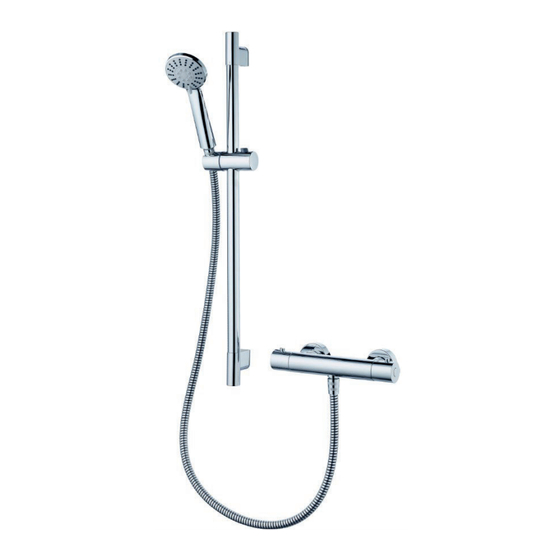
Summary of Contents for Ideal-Standard Ecotherm A7255AA
- Page 1 Ecotherm thermostatic bar shower valve & kit A7255AA & A7256AA Shower valve pack with three function shower handset, hose & riser rail.
-
Page 2: Table Of Contents
TABLE OF CONTENTS PRODUCT BOX CONTENTS PRODUCT DIMENSIONS INTRODUCTION SUPPLY CONDITIONS W ATER REGULATIONS PRE-INSTALLATION NOTES SHOW ER VALVE INSTALLATION RISER KIT INSTALLATION SHOW ER VALVE OPERATION SHOW ER HANDSET FUNCTIONS SHOW ER HEIGHT ADJUSTMENT HANDLE REMOVAL 10.1 MAXIMUM TEMPERATURE STOP MAINTENANCE COMMISSIONING &... -
Page 3: Product Box Contents
1. PRODUCT BOX CONTENTS Combined convex strainer & seal, x2 Three function Screw pack for shower handset, wall kit: Screws fitted with 8 L/min x6 (33 long) & flow regulator wall plugs x6 (Ø6x27 long) Screw pack for riser rail: Screws x4 (60 long) &... -
Page 4: Product Dimensions
2. PRODUCT DIMENSIONS Dimensions are in millimetres & may vary within permitted tolerances. Ø85 Three function hand shower Riser rail, & sliding bracket Complete bar shower mixer valve... -
Page 5: Introduction
3. INTRODUCTION WATER REGULATIONS Hot and cold water supply pressures must be reasonably balanced and from a common source - both from storage or both from a supply pipe. (IRN 101). This mixer will function within specification on unequal pressures up to a ratio of 2:1, but it is not recommended that the cold supply be connected to the rising main and hot to the tank fed supply as the pressure differential is likely to exceed the 2:1 ratio. -
Page 6: Supply Conditions
Flow rate table Service valves MUST be fitted to the supply pipes to permit future maintenance. Strainers (mesh filters) are integral to the mixer body. These should be fitted as close as is practicable to the water supply inlets of the thermostatic shower valve. -
Page 8: Pre-Installation Notes
6. PRE-INSTALLATION NOTES Product box contents. Ensure you have all the parts shown in section 1. Product dimensions. Check the dimensions shown in section 2, ensuring the mixer will fit on the intended wall. Plan the fitting location of the shower kit. Product location. -
Page 9: Shower Valve Installation
7. SHOWER VALVE INSTALLATION Product is supplied with a pair of wall mount escutcheons. Mixers are intended to be installed on a solid wall or panel. Both hot & cold water supply pipes should be securely attached to a wall using suitable fixing clips. fix: pipe installation Two 15mm water supply pipes need to be run COLD... - Page 10 Place the mounting brackets over the protruding supply pipes, recheck pipes are still 150mm apart and level. Mark the three screw hole positions through the mounting brackets onto the mounting surface. Ensure that the positions of the holes will not result in damage to the pipework inside the wall cavity during drilling.
- Page 11 When the sealant has set, fit the covers by screwing them onto the adaptors until they are flush with the wall. The covers only need to be hand tight. NOTE: First remove the protective plastic caps which are fitted to both inlets & the shower outlet of the mixer Ensure the sealing washers are placed within the captive nuts of the shower mixer.
-
Page 12: Riser Kit Installation
8 RISER KIT INSTALLATION To install the riser rail, it is necessary to screw the upper & lower brackets onto the finished mounting surface at the desired location. Each bracket requires two screws (supplied). The distance between the inner two screws of the mounting brackets is 585mm as shown. -
Page 13: Shower Valve Operation
9.0 SHOWER VALVE OPERATION 38°C Left handle controls water flow rate. • This handle is shown above parked in the off position. • Rotating this handle backwards (anti-clockwise) commences water flow. By rotating the handle further backwards to the stop, it will increase the flow to the maximum of the product. •... -
Page 14: Shower Handset Functions
9.1 SHOWER HANDSET FUNCTIONS 1. Outer spray. 2. Full spray. 3. Massage. Three function hand shower The small lever on the handset can be rotated in either direction to select the different jet-spray patterns. 9.2 SHOWER HEIGHT ADJUSTMENT To adjust the height of the shower handset, simply press & hold the button on the top of the bracket. -
Page 15: Maximum Temperature Stop
10.1 MAXIMUM TEMPERATURE STOP Maximum hot water is obtained by pressing the override button & going pass the 38°C marker. This shower mixer is factory set with the temperature stop at max. 44 C.If after commissioning, the maximum temperature should be checked & adjusted if necessary. To set maximum temperature: A. -
Page 17: Cold W Ater Isolation Test
14. COLD WATER ISOLATION (CWI) TEST CWI test is a guide to showing the performance of the thermostat. Prior to CWI test: • Make sure the supply temperatures are within the ranges 55 to 65°C for hot, & 5 to 20°C for cold. -
Page 18: Thermostatic Cartridge Replacement
16. THERMOSTATIC CARTRIDGE REPLACEMENT 24mm This thermostatic cartridge is protected from water borne debris by mesh filter screens. These should be checked and cleaned before contemplating replacing the cartridge. To replace the thermostatic cartridge: (FIRST SEE HANDY TIPS, in section 15). A. -
Page 19: Check Valves Replacement
18. CHECK VALVES REPLACEMENT Check valves and strainers (mesh filters) should be regularly serviced particularly in hard water areas. The check valves along with the strainers are located in the retaining nut. 30mm 10mm To replace the check valves: (FIRST SEE HANDY TIPS, in section 15). A. -
Page 20: Spare Parts
An in-line combined service valve (shown here) can be purchased by contacting Customer Care. Spares code E960613NU contains a pair of these valves, suitable for 15mm supply pipes. This valve also contains a flow regulator and check valve (which can be removed if not required). 20. -
Page 22: Spare Parts List
SPARE PARTS LIST... -
Page 23: Cleaning Chrome Surfaces
21. CLEANING CHROME SURFACES Whilst this product has a high quality durable chrome finish, it should nevertheless be treated with care. When cleaning chromed products use only a mild detergent, rinse & wipe dry with a soft cloth. Ideally clean after each use to maintain appearance. Never use abrasive, scouring powders or scrapers. - Page 24 Ideal Standard pursues a policy of continuing improvement in design and performance of its products. This is therefore reserved to vary specification without notice. Ideal Standard is a division of: Ideal Standard (UK) Ltd. Ideal Standard, The Bathroom Works, National Avenue Kingston-Upon-Hull, HU 4HS, England.
Need help?
Do you have a question about the Ecotherm A7255AA and is the answer not in the manual?
Questions and answers