Table of Contents
Advertisement
Thermostatic, exposed, two hole, rim
& wall mounted bath /shower mixers
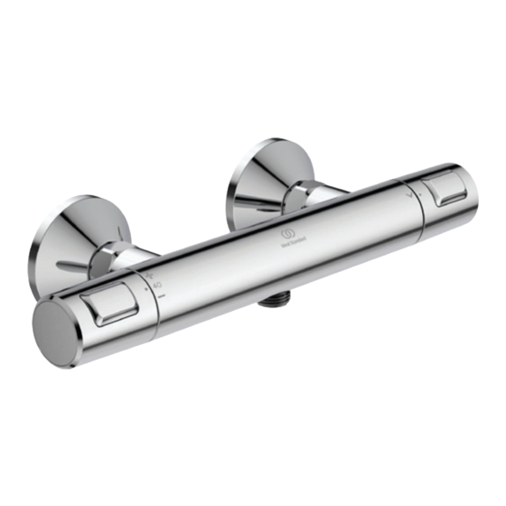
Ceratherm T25
A7202AA bar shower
mixer without shower kit
A7207AA bath shower
mixer without shower kit
A7215AA & A861383AA
wrap over shower shelves
A7698AA bath shower mixer
pack with 600 rail & Hand spray
BEFORE CONNECTION, FLUSH WATER THROUGH PIPEWORK TO REMOVE
ALL DEBRIS ETC. WHICH COULD DAMAGE THE VALVE MECHANISM
INSTALLER:
After installation please pass this instruction booklet to user
+
+
A7205AA bar shower mixer
pack with 600 rail & Hand spray
IMPORTANT
INSTALLATION
INSTRUCTIONS
A7209AA bar
shower mixer dual
pack with overhead
Rain shower & Hand
spray
Advertisement
Table of Contents

Subscribe to Our Youtube Channel
Related Manuals for Ideal-Standard Ceratherm T25


Summary of Contents for Ideal-Standard Ceratherm T25
- Page 1 INSTALLATION Thermostatic, exposed, two hole, rim INSTRUCTIONS & wall mounted bath /shower mixers Ceratherm T25 A7202AA bar shower mixer without shower kit A7207AA bath shower mixer without shower kit A7215AA & A861383AA A7209AA bar wrap over shower shelves shower mixer dual pack with overhead Rain shower &...
-
Page 2: Table Of Contents
TABLE OF CONTENT DIMENSIONS ....................3 WALL MOUNT MIXERS A7202AA; A7205AA; A7209AA ........3 DECK MOUNT MIXERS A7207AA & A7698AA ..........3 SHOWER PACKS ....................4 PRODUCT BOX CONTENTS ..............5 WALL MIXERS A7202AA; A7205AA; A7209AA ..........5 DECK MOUNT MIXER A7207AA & A7698AA ........... 6 INTRODUCTION .................. -
Page 3: Dimensions
DIMENSIONS Dimensions are in millimetres & may vary within permitted tolerances Wall mount mixers A7202AA; A7205AA; A7209AA G 1/2 Basic bar shower mixer dimensions shown with wall mounting brackets assembled Ø70 Dimensions same for A7205AA Dimensions same for A7209AA bar Shown above, A7202AA bar shower mixer pack with 600 shower mixer dual pack with overhead... -
Page 4: Shower Packs
SHOWER PACKS Dimensions are in millimetres & may vary within permitted tolerances Ø200 Ø80 79,5 Ø50 Ø100 M1 Ø200 Rain shower. S3 three function handset, Ø100 hand spray & 1500 hose. S3 three function handset, Ø80 hand spray, 600 rail & 1250 hose. L=1250 L=1500 A7209AA... -
Page 5: Product Box Contents
PRODUCT BOX CONTENTS Wall mixers A7202AA; A7205AA; A7209AA Fibre washer seals with integral strainers, -pair Wall marking template Wall mounting bracket assemblies -pair NOTE: This wall mount kit is supplied with all 3 products A7209AA Shower valve shown without wall mounting brackets. Shower valve shown without wall Right handle controls flow &... -
Page 6: Deck Mount Mixer A7207Aa & A7698Aa
NOTE: Shower kits have to be carefully assembled during installation, chrome parts are packaged individually to prevent damage. The shower kits shown are supplied with their own fitting instructions. Deck mount mixer A7207AA & A7698AA Kit for rim (deck) mount product Fibre washer seals with integral strainers, -pair Deck bath legs kit,... -
Page 7: Introduction
INTRODUCTION The fittings covered by these instructions should be installed in accord- ance with the Water Regulations published in 1999*. Ideal Standard strongly recommends that these fittings are installed by a professional fitter. *A guide to the Water Supply (Water Fittings) Regulations 1999 and the Water Byelaws 2000, Scotland is published by WRAS (Water Regulations Advisory Scheme) Unit 13, Willow Road, Pen-y-Fan Industrial Estate, Crumlin, Gwent, NP11 4EG. -
Page 8: Water Supply Conditions
WATER SUPPLY CONDITIONS Introduction These thermostatic shower mixers are manufactured to the highest standards.The mixer is intended to be installed on high pressure systems (1.0 bar or greater). The mixer has safety features such as cool body technolgy and temperature limit stop. To make installation easier, fast fix wall mounts are supplied. Ø15mm water supply pipes should be installed at 150mm horizontal centres in the wall, behind a shower panel or tiled duct wall. -
Page 9: Water Regulations
WATER REGULATIONS CATEGORIES OF RISK The water regulations published in 1999* take a new approach to backflow in that they look at different categories of risk. The installer must assess the risk from the various categories of fluid in adjacent appliances before determining the level of backflow protection required for a particular installation. -
Page 10: Pre-Installation Notes
TMV, its valves and the commissioning and testing of the TMV can be undertaken. Ceratherm T25 is an exposed two hole thermostatically controlled shower mixer. This product is designed to provide water from ambient cold up to a safe maximum temperature for bathing. -
Page 11: Installation
INSTALLATION IMPORTANT BEFORE CONNECTION, FLUSH WATER THROUGH PIPEWORK TO REMOVE ALL DEBRIS ETC. WHICH COULD DAM- AGE THE VALVE MECHANISM Wall mount mixers A7202AA, A7205AA, & Pair of wall brackets with connectors & A7209AA escutcheons Template x1 Ø15mm copper supply pipes should be run within the wall cavity. Hot supply pipe should be on the left hand side and the cold on the right. - Page 12 Place the brackets over the exposed pipes and use the template provided to position them 150mm apart. Mark the hole positions for the fixings onto the mounting surface. Ensure that the positions of the holes will not result in damage to the pipework inside the wall cavity during drilling.
- Page 13 The covers only need to be hand tight. Note: Ceratherm T25 range is supplied with conical wall escutcheons. Other T ranges have cylindrical escutcheons. Assemble the shower valve to...
-
Page 14: Deck Mount Mixer A7207Aa & A7698Aa
Note: the mixer supplied with A7209AA is fitted with an additional outlet nipple on the top surface to connect the over head shower plate. Smear a small amount of approved sili- cone grease onto the O-ring fitted on the nipple. This will help to prevent damage to the O-ring during assembly. -
Page 15: Quick Overview Of Overhead Shower Pack Installation A7209Aa
Quick overview of overhead shower pack installation A7209AA Fittings grease Graisse de robinetterie Grasso per rubinetti Kraanvet Grasa de griferia Armaturenfett Ø 6 min. 10 Nm... -
Page 16: Operating Product
OPERATING PRODUCT Q=0% Q=50% Shower mixer handle flow Q=100% control positions (Q= flow rate) NOTE: the functionality of the temperature control handle is the same for all the products in the T25 range. A7209AA has a basic flow control handle, the other products have integral flow control &... - Page 17 Q=0% Q=50% Q=100% Right handle controls the 3 function diverter (for product A7209AA) • This handle is shown above parked in the off position (giving no flow at this position). • Rotating this handle downwards from the parked position, commences water flow & will direct water to the bottom outlet of the mixer.
-
Page 18: Temperature Adjustment
TEMPERATURE ADJUSTMENT If the mixer is not discharching 40°C water when the temperature handle is parked & aligned with the body, then (if desired) this can be adjusted as follows: 40°C 40°C 1-2. First remove the temperature control handle (left side) as detailed in section 16, steps 1 to 3. Before sliding the handle off, ensure the dot on the handle is inline with the 40 marker on the mixer. -
Page 19: Commissioning & Periodic Checks
COMMISSIONING & PERIODIC CHECKS The following procedures should be carried out after installation and every 12 months after to ensure that the valve is functioning correctly. Check that: 1. The application of the thermostatic valve matches the approved designation. 2. The supply pressures are within the recommended range for the application. 3. -
Page 20: Cold Water Isolation (Cwi) Test
COLD WATER ISOLATION (CWI) TEST CWI test is a guide to showing the performance of the thermostat. Prior to CWI test: • Make sure that the temperature handle is aligned in the 40°C position. • Make sure the supply temperatures are within the ranges 55 to 65°C for hot, & 5 to 20°C for cold. •... -
Page 21: Disassembly Sequence Of Maintenance
THERMOSTATIC CARTRIDGE AGEING Following many years of normal service you may notice the following: 1. The need to carry out more frequent adjustment of mixed temperature. 2. The thermostatic element may not pass the CWI test. These issues could be due to the ageing of the thermostat which loses some expansion capability over time. - Page 22 Method for demounting mixer: 1. Observe disassembling sequence, as detailed in section 14, steps 1 & 2. 2. Remove the overhead shower assembly, if fitted (A7209AA only). 3. Undo the two coupling nuts located at the rear of the mixer (see fig above). Take care not to lose the two sealing /strainer washers.
-
Page 23: Handle Removal For Cartridge Access
HANDLE REMOVAL FOR CARTRIDGE ACCESS Handle dot marker To gain access to either the thermostatic, flow or diverter cartridges, it will be necessary to remove the appropriate handle. 1. Carefully prise out the chrome end cap fitted to the handle. Look for a small notch in the handle, then use a sharp blade to lever the cap out, taking care not to damage the chromed surfaces. -
Page 24: Thermostatic Cartridge Replacement
THERMOSTATIC CARTRIDGE REPLACEMENT Cartridge stop max. 5 Nm Use the following method to inspect or replace the thermostatic cartridge: 1. Observe the disassembling sequence, see section 14, steps 1 to 3. 2. Remove the temperature control handle (left side) as detailed in section 16, steps 1 to 3. 3. -
Page 25: Diverter Replacement
DIVERTER REPLACEMENT A7209AA 1. Observe disassembling sequence, as detailed in section 14, steps 1 to 3. 2. Remove the flow diverter handle (right side) as detailed in section 16 steps 1 to 4. 3. Slide off the stop sleeve. 4. Using a 28mm spanner or socket, undo the threaded collar & slide out. The diverter cartridge should now slide out of the mixer’s bore complete with O-ring. -
Page 26: Flow Cartridge Replacement
FLOW CARTRIDGE REPLACEMENT A7231AA Stop ring min. 16 Nm max. 18 Nm Stop Align ring 1. Observe disassembling sequence, as detailed in section 14, steps 1 to 3. 2. Remove the flow control handle (right side) as detailed in section 16 steps 1 to 4. 3. -
Page 27: Check-Valve Replacement
CHECK-VALVE REPLACEMENT 1. Demount the mixer body from the wall, as detailed in section 15, follow steps 1 to 4. 2. Locate the sealing washers (with integral strainers) from inside the mixer’s inlet bores & keep them in a safe location. Strainer washers Observe flow... -
Page 28: Diverter Cartridge Replacement
DIVERTER CARTRIDGE REPLACEMENT A7207AA & A7698AA The diverter mechanism is available as a cartridge unit. To replace the diverter cartridge: 1. Remove the shower hose from the shower outlet. 2. Unscrew the diverter knob on the top of the bath spout & lift off. 3. -
Page 29: Spare Parts
SPARE PARTS A7202AA Bath/Shower mixer w/o shower kit A7205AA Bath/Shower mixer with shower kit 23.1 A7202AA & A7205AA Pos. Description Part No. Qty. Handle cpl. A 861 370 AA 1 Set Thermostatic Cartridge cpl. A 861 371 NU 1 pcs Stopring A 861 373 NU 1 pcs... -
Page 30: A7207Aa & A7698Aa
23.2 A7207AA & A7698AA A7207AA Bath/Shower mixer w/o shower kit A7698AA Bath/Shower mixer with shower kit Pos. Description Part No. Qty. Handle cpl. A 861 370 AA 1 Set Thermostatic Cartridge cpl. A 861 371 NU 1 pcs Stopring A 861 373 NU 1 pcs Cartridge G1/2 180°... -
Page 31: A7209Aa
23.3 A7209AA Exposed Thermostatic Bar Shower Mixer – with overhead Rain shower & Hand spray 2 lenghts of pipe extension available Handspray Ø100-3F-8l/min B 9403 AA 1 pcs Pos. Description Part No. Qty. Shower bar 1100 mm A 861 377 AA 1 pcs Handle cpl. -
Page 32: Inline Service Valves
INLINE SERVICE VALVES Inline service valves (not supplied with this product) MUST be fitted to permit future maintenance of the cartridges. They also facilitate the cold water isolation test. These should be fitted as close as is practicable to the water supply inlets of the thermostatic shower valve.
Need help?
Do you have a question about the Ceratherm T25 and is the answer not in the manual?
Questions and answers