
Related Manuals for HP FlexNetwork MSR 954


Summary of Contents for HP FlexNetwork MSR 954
- Page 1 HPE FlexNetwork MSR 954 Routers Installation Guide Part number: 5998-8750 Document version: 6W103-20160516...
- Page 2 © Copyright 2016 Hewlett Packard Enterprise Development LP The information contained herein is subject to change without notice. The only warranties for Hewlett Packard Enterprise products and services are set forth in the express warranty statements accompanying such products and services. Nothing herein should be construed as constituting an additional warranty. Hewlett Packard Enterprise shall not be liable for technical or editorial errors or omissions contained herein.
-
Page 3: Table Of Contents
Contents Preparing for installation ················································································· 1 Safety recommendations ··································································································································· 1 Safety symbols ··········································································································································· 1 General safety recommendations ·············································································································· 1 Electricity safety ········································································································································· 1 ESD prevention ·········································································································································· 2 Examining the installation site ···························································································································· 2 Temperature and humidity ························································································································· 2 Cleanliness ················································································································································· 2 Cooling ·······················································································································································... - Page 4 Reset button usage guidelines ················································································································· 27 Appendix A Chassis views and technical specifications ······························· 29 Chassis views ·················································································································································· 29 JH296A ···················································································································································· 29 JH297A ···················································································································································· 30 JH298A ···················································································································································· 30 JH299A ···················································································································································· 31 JH373A ···················································································································································· 32 Technical specifications ··································································································································· 32 Appendix B LEDs ·························································································· 34 LEDs ································································································································································...
-
Page 5: Preparing For Installation
Preparing for installation The HPE MSR954 Router Series includes the models in Table Table 1 HPE MSR954 Router Series models Product code HPE description JH296A HPE MSR95X 1GbE+SFP Router BJNGA-BB0036 JH297A HPE MSR95X-W 1GbE+SFP (WW) Router BJNGA-BB0037 JH298A HPE MSR95X-W 1GbE+SFP LTE (AM) Router BJNGA-BB0038 JH299A HPE MSR95X-W 1GbE+SFP LTE (WW) Router... -
Page 6: Esd Prevention
• Do not work alone when the router has power • Always make sure the power has been disconnected during installation or replacement. ESD prevention WARNING! Check the resistance of the ESD wrist strap for safety. The resistance reading should be in the range of 1 to 10 megohm (Mohm) between a human body and the ground. -
Page 7: Cooling
Table 3 Dust concentration limit in the equipment room Substance Concentration limit (particles/m ≤ 3 x 10 Dust particles (No visible dust on the tabletop in three days) NOTE: Dust diameter ≥ 5 µm The equipment room must also meet strict limits on salts, acids, and sulfides to eliminate corrosion and premature aging of components, as shown in Table Table 4 Harmful gas limits in an equipment room... -
Page 8: Installation Accessories And Tools
Installation accessories and tools Table 5 Installation accessories Product code Description Quantity Applicable models 4G antenna • JH298A JG669A • JH299A 4G antenna • JH373A JG669A WLAN antenna • JH297A • JH298A 5189-9346 • JH299A • JH296A Grounding cable • JH297A •... -
Page 9: Pre-Installation Checklist
Product code Description Quantity Applicable models • JH296A Rubber feet • JH297A • JH298A 5184-7298 1 kit • JH299A • JH373A Bail latch • JH296A • JH297A 5190-1728 1 kit • JH298A • JH299A • JH296A Console cable • JH297A •... - Page 10 Item Requirements • The router is reliably grounded. • The AC power receptacle is reliably grounded. Lightning • (Optional.) Port lightning protectors are available. A signal protection lightning arrester is required at the input end of an external signal cable. •...
-
Page 11: Installing The Router
Installing the router WARNING! To avoid injury, do not touch bare wires, terminals, or parts with high-voltage hazard signs. IMPORTANT: • The barcode on the router chassis contains product information that must be provided to local sales agent when you return a faulty router for repair. •... -
Page 12: Installing The Router
Figure 2 Installation flowchart Installing the router Mounting the router on a workbench IMPORTANT: • Make sure the workbench is clean, stable, and reliably grounded. • Maintain a minimum clearance of 10 cm (3.9 in) around the router for heat dissipation. •... -
Page 13: Mounting The Router On A Wall
Figure 3 Mounting the router on a workbench Mounting the router on a wall Mark two screw hole locations on the wall. Drill holes with a minimum depth of 22 mm (0.87 in) in the marked locations. Use a hammer to tap an anchor into each hole until the anchor end is flush with the wall. Drive a screw into each anchor and make sure the screw protrudes a minimum of 1.5 mm (0.06 in) from the wall. -
Page 14: Installing The Router In A Rack
Figure 4 Wall-mounting the router ≥ 22 mm (0.87 in) 160 mm (6.30 in):JH296A/JH297A/JH298A/ ≥ 1.5 mm JH299A (0.06 in) 240mm(9.45in):JH373A Installing the router in a rack CAUTION: The mounting brackets can support only the weight of the router. Do not place objects on the router. - Page 15 Figure 5 Marking cage nut installation holes Install the cage nuts, as shown in Figure a. Insert one ear of a cage nut into the marked installation hole. b. Use a flathead screwdriver to push another ear into the same hole. Figure 6 Installing cage nuts...
-
Page 16: Grounding The Router
Attach mounting brackets to both sides of the router, as shown in Figure Figure 7 Attaching mounting brackets to the router Use M6 screws to attach the mounting brackets on the router to the front rack posts, as shown in Figure Figure 8 Securing the router to the rack Grounding the router... - Page 17 Grounding the router with a grounding strip Remove the grounding screw from the grounding hole in the chassis. Use the grounding screw to attach the ring terminal of the grounding cable to the grounding hole. Use a screwdriver to fasten the grounding screw. Connect the other end of the grounding cable to the grounding strip.
-
Page 18: Installing A 4G Sim Card (Jh296A/Jh297A/Jh298A/Jh299A)
Installing a 4G SIM card (JH296A/JH297A/JH298A/JH299A) CAUTION: • Do not hot-swap a 4G SIM card. • To avoid damaging the SIM card slot, do not use excessive force when installing a 4G SIM card. To install a 4G SIM card: Remove the screw on the 4G SIM card slot cover and take off the cover. - Page 19 Figure 12 Removing the 4G SIM card socket cover Install SIM 1 and SIM 2. Figure 13 Install SIM 1 and SIM 2.
- Page 20 Push the 4G SIM card holder in the direction marked "OPEN" so the holder projects upwards. Do not insert the 4G SIM card to the card holder before projecting the card holder up or lift the holder forcibly. Figure 14 Incorrect installations Insert the 4G SIM card along the slide rails to the holder.
-
Page 21: Installing A Micro Sd Card
Position the 4G SIM card socket cover and fasten the screws on the cover. Figure 16 Installing the 4G SIM card socket cover Installing a Micro SD card CAUTION: To avoid damaging the Micro SD card slot, do not use excessive force when you install a Micro SD card. -
Page 22: Installing A 4G Antenna
Installing a 4G antenna Only the JH298A,JH299A and JH373A routers support 4G antennas. To install a 4G antenna: Change the angle of the antenna orientation from vertical to horizontal. Attach the 4G antenna to the 4G antenna port on the router. Do not over-tighten the antenna to avoid damage. -
Page 23: Connecting A 4G Antenna Extension Cable To A 4G Router
Connecting a 4G antenna extension cable to a 4G router Only the JH373A router support 4G antenna extension cable. A 4G antenna extension cable is not provided with the router. To use a 4G antenna extension cable, purchase it separately. To install a 4G antenna extension cable: Thread the male connector of the cable through the hole on the bracket, and use screws (from behind the bracket) to secure the male connector to the bracket. -
Page 24: Connecting Ethernet Interface Cables
Connecting Ethernet interface cables Connect one end of the cable to an Ethernet port on the router. Connect the other end of the cable to the Ethernet port on a host. Examine the port LEDs on the router. For more information about the LEDs, see "LED description."... -
Page 25: Connecting The Power Cord
Figure 23 Connecting the console cable Setting configuration terminal parameters To access the device through the console port, you must run a terminal emulator program (HyperTerminal, PuTTY, or Tera Term) on the configuration terminal. For information about using a terminal emulator program, see the program's user guide. The following are the required terminal settings: •... -
Page 26: Verifying The Installation
Figure 25 Connecting a power adapter Verifying the installation After you complete the installation, verify the following information: • There is enough space around the router for heat dissipation. • The router is securely installed. • Antennas and USB devices are installed correctly. •... -
Page 27: Power-On Check
HPE MSR954 BootWare, Version 9.00 **************************************************************************** Copyright (c) 2010-2016 Hewlett Packard Enterprise Development LP Compiled Date : Jan 2 2016 CPU ID : 0x1 Memory Type : DDR3 SDRAM Memory Size : 1024MB Flash Size : 2MB Nand Flash size : 256MB CPLD Version : 2.0... -
Page 28: Configuring Basic Settings For The Router
• The configuration terminal displays information correctly. You can see the startup window on the local configuration terminal. For more information, see "Observing the startup process." • After completing the POST, the system prompts you to press Enter. When the command line prompt appears, the router is ready to configure. -
Page 29: Troubleshooting
Troubleshooting IMPORTANT: • The barcode on the router chassis contains product information that must be provided to local sales agent when you return a faulty router for repair. • Keep the tamper-proof seal on a mounting screw on the chassis cover intact, and if you want to open the chassis, contact Hewlett Packard Enterprise for permission. -
Page 30: Garbled Display On The Configuration Terminal
Verify that the console cable is in good condition. If the problem persists, contact Hewlett Packard Enterprise Support. Garbled display on the configuration terminal Symptom The configuration terminal has garbled display when the router is powered on. Solution To resolve the problem: Verify that the following settings are configured for the terminal: Baud rate—9,600. -
Page 31: Restoring The Factory Settings
If the problem persists, contact Hewlett Packard Enterprise Support. Restoring the factory settings Scenario 1 Symptom When you replace the router, the router password is lost. As a result, you cannot log in to the router and do not know the router configuration. Solution Because the router is replaced, you do not need to save the configuration of the router. - Page 32 Figure 26 Reset button...
-
Page 33: Appendix A Chassis Views And Technical Specifications
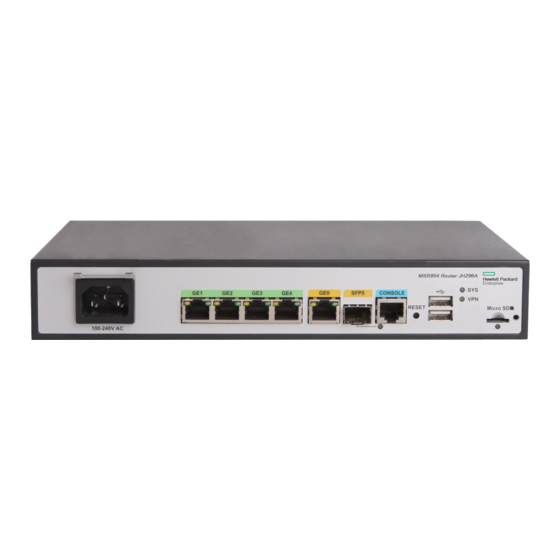
Appendix A Chassis views and technical specifications Chassis views The figures in this appendix are for illustration only. JH296A Figure 27 Front view (1) AC power receptacle (2) Gigabit Ethernet LAN ports (3) Gigabit Ethernet WAN port (GE0) (GE1 to GE4) (4) Gigabit fiber port (SFP5) (5) Console port (6) USB port... -
Page 34: Jh297A
JH297A Figure 29 Front view (1) AC power receptacle (2) Gigabit Ethernet LAN ports (3) Gigabit Ethernet WAN port (GE0) (GE1 to GE4) (4) Gigabit fiber port (SFP5) (5) Console port (6) USB port (7) Micro SD card slot (8) USB port (9) Reset button (RESET) Figure 30 Rear view (1) Grounding screw... -
Page 35: Jh299A
Figure 32 Rear view (1) Grounding screw (2) LTE antenna port 1 (3) 2.4G WLAN antenna port (4) 4G SIM card slot (5) 2.4G WLAN antenna port (6) LTE antenna port 2 JH299A Figure 33 Front view (1) AC power receptacle (2) Gigabit Ethernet LAN ports (3) Gigabit Ethernet WAN port (GE0) (GE1 to GE4) -
Page 36: Jh373A
JH373A Figure 35 Front view (1) 4G antenna auxiliary connector (DIV1) (2) USB port (3) Reset button (RESET) (4) 4G antenna main connector (MAIN1) Figure 36 Rear view (1) Serial port (2) 4G antenna main connector (3) 4G antenna auxiliary (MAIN2) connector (DIV2) (4) Power adapter receptacle... - Page 37 Item JH296A JH297A JH298A JH299A JH373A Dimensions (H × 43.6 × 266 × 43.6 × 266 × 43.6 × 266 × 43.6 × 266 × 44.2 × 300 × W × D) (excluding 161 mm (1.72 161 mm (1.72 161 mm (1.72 161 mm (1.72 200 mm (1.74 rubber feet and...
-
Page 38: Appendix B Leds
Appendix B LEDs LEDs JH296A Figure 37 Front panel LEDs (1) GE port yellow LED (2) GE port green LED (3) System status LED (SYS) (4) Micro SD card LED (5) VPN status LED (6) SFP port LED JH297A Figure 38 Front panel LEDs (1) GE port yellow LED (2) GE port green LED (3) System status LED (SYS) -
Page 39: Jh298A
JH298A Figure 39 Front panel LEDs (1) GE port yellow LED (2) GE port green LED (3) System status LED (SYS) (4) VPN status LED (5) Micro SD card LED (6) LTE LED (7) 2.4G WLAN LED (8) SFP port LED JH299A Figure 40 Front panel LEDs (1) GE port yellow LED... -
Page 40: Jh373A
JH373A Figure 41 Front panel LEDs (1) System status LED (SYS) (2) VPN status LED (VPN) (3) 4G status LED (WWAN1) (4) Received 4G signal strength (5) 4G status LED (WWAN2) (6) Received 4G signal strength indication LED (RSSI1) indication LED (RSSI2) Figure 42 Rear panel LEDs (1) Serial port link status LED (LINK) (2) Serial port data transmission status LED (ACT) - Page 41 Status Description Steady green The SDRAM is performing self-test. The system software image is being copied Flashing green (8 Hz) and decompressed. Comware has started with the configuration Flashing green (1 Hz) file and the router has booted up. System status LED (SYS) Flashing yellow (1 Hz) The SDRAM has failed the self-test.
- Page 42 Status Description Data is being received or transmitted. The Flashing green (8 Hz) router is operating in 4G mode. The router has been connected to the Steady yellow wireless network and is operating in 3G mode. Data is being received or transmitted. The Flashing yellow (8 Hz) router is operating in 3G mode.
-
Page 43: Document Conventions And Icons
Document conventions and icons Conventions This section describes the conventions used in the documentation. Port numbering in examples The port numbers in this document are for illustration only and might be unavailable on your device. Command conventions Convention Description Bold text represents commands and keywords that you enter literally as shown. Boldface Italic text represents arguments that you replace with actual values. -
Page 44: Network Topology Icons
Network topology icons Convention Description Represents a generic network device, such as a router, switch, or firewall. Represents a routing-capable device, such as a router or Layer 3 switch. Represents a generic switch, such as a Layer 2 or Layer 3 switch, or a router that supports Layer 2 forwarding and other Layer 2 features. -
Page 45: Support And Other Resources
Hewlett Packard Enterprise Support Center More Information on Access to Support Materials page: www.hpe.com/support/AccessToSupportMaterials IMPORTANT: Access to some updates might require product entitlement when accessed through the Hewlett Packard Enterprise Support Center. You must have an HP Passport set up with relevant entitlements. -
Page 46: Websites
Websites Website Link Networking websites Hewlett Packard Enterprise Information Library for www.hpe.com/networking/resourcefinder Networking Hewlett Packard Enterprise Networking website www.hpe.com/info/networking Hewlett Packard Enterprise My Networking website www.hpe.com/networking/support Hewlett Packard Enterprise My Networking Portal www.hpe.com/networking/mynetworking Hewlett Packard Enterprise Networking Warranty www.hpe.com/networking/warranty General websites Hewlett Packard Enterprise Information Library www.hpe.com/info/enterprise/docs Hewlett Packard Enterprise Support Center... -
Page 47: Documentation Feedback
Documentation feedback Hewlett Packard Enterprise is committed to providing documentation that meets your needs. To help us improve the documentation, send any errors, suggestions, or comments to Documentation Feedback (docsfeedback@hpe.com). When submitting your feedback, include the document title, part number, edition, and publication date located on the front cover of the document. For online help content, include the product name, product version, help edition, and publication date located on the legal notices page. -
Page 48: Index
Index grounding router with grounding strip, Numerics grounding the router, 4G antenna powering on the router, technical specifications, electricity electrical cooling requirements, electromagnetic interference. Use EMI troubleshooting power supply failure, EMI prevention, accessories (installation), safety recommendations, Appendix troubleshooting power supply failure, A chassis views and technical EMI prevention, specifications,... - Page 49 humidity port (troubleshooting no response), installation site requirements, power cooling requirements, power cord AC power, installation flowchart, power supply Installing connecting power cord, 3G/4G antenna extension cable, troubleshooting failure, installing powering on (router), 4G SIM card, 14, power-on check, accessories required, pre-installation checklist, cooling requirements, preventing...
- Page 50 installation site gas saturation, installation site humidity, installation site temperature, lightning protection, setting console terminal parameters, site cleanliness, cooling requirements, dust concentration, examination, gas saturation, humidity, temperature, startup process, technical specifications, 4G antenna, LED, 34, temperature installation site requirements, site cooling requirements, terminal setting console parameters, troubleshooting garbled display,...
Need help?
Do you have a question about the FlexNetwork MSR 954 and is the answer not in the manual?
Questions and answers