Table of Contents
Advertisement
Quick Links
Advertisement
Table of Contents

Related Manuals for multicomp pro MP720646 Series


Summary of Contents for multicomp pro MP720646 Series
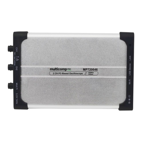
- Page 1 MP720646 Two-Channel Series PC Based Oscilloscope User Manual...
-
Page 2: Table Of Contents
Table of Contents I. General Safety Requirements ........................ II. Safety Terms and Signs .......................... III. PC Configuration Requirements ......................IV. Communication Interface Introduction ................... V. How to Communicate the Device with PC ..................i. software installation solution ..................... ii. to install NI-VISA driver ......................iii. -
Page 3: General Safety Requirements
I. General Safety Requirements Before first use, please read the following safety precautions to avoid any possible personal injury and prevent this product or any other products connected to it from damage. Safety Warnings Check that the voltage indicated on the rating plate corresponds with that of the local network before connecting the appliance to the mains power supply. -
Page 4: Safety Terms And Signs
Safety Terms and Signs Safety Terms Terms in this quick guide. It covers, Warning which indicates the condition or the operation that may cause human body injury or permanent life loss. Caution indicates the conditions or practices that could result in damage to this product or other connected devices. -
Page 5: Electrical Outlet
To avoid possible human injury, and / or device damage, and / or its accessory or communicating facility damage, before working the device, we strongly recommend to read the following safety information. Warning To avoid any potential short circuit or electric shock, DO use the power adapter of original local standard. Warning The channels of the device is non-isolated electrically. - Page 6 Warning When the device input is connected to a voltage larger than 42 Vp-p (30Vrms), or on circuit of 4800+VA, to avoid any potential short circuit or electric shock - i. Always use the probes that came with the device. ii.
-
Page 7: Pc Configuration Requirements
III. PC Configuration Requirements Minimum System Requirement CPU: Pentium® 4/ 2.4 GHz Internal Memory: Effective Hard Disk Space: Recommended System Requirement CPU: Pentium® Dual-Core/ 2.4 GHz Internal Memory: Effective Hard Disk Space: Other Requirement Operating System: Windows 10, or Windows 8 / 7 / Vista / XP (32-bit, or 64-bit) Communication Interface: USB 2.0, or USB1.1;... -
Page 8: Communication Interface Introduction
IV. Communication Interface Figue IV-1. Communication Interface of the Device 1. power input: for AC-DC adapter 2. USB host: for extension 3. USB device (type-C): for PC communication Note: when the device powered by PC through USB connection cable (via USB communication interface of PC, with PC powered by AC power source), without adapter connection, the input current should reach 1.5A or above 4. -
Page 9: How To Communicate The Device With Pc
V. How to Communicate the Device with PC to communicate the device with PC, it’s a must to install software firstly. i. software installation solution i). full installation Target user(s): general PC oscilloscope user(s), and programmer(s) gets secondary development need Installation process - On the basis that NI-VISA driver or similar VISA driver is already installed on the PC, to install “PC_OSC_Software.exe”... - Page 10 click “Yes” to continue, and following window displays, tick "I accept the above license agreement", then "Next",...
- Page 11 click “Next”, to enter into NI Package Manager processing window, then this window displays, followed by additional installation window...
- Page 12 to select additional items you may wish to install, use scroll bar, to select more necessary options, from here...
- Page 13 tick "I accept the above 2 license agreements", followed by "Next", from this window tick "I accept the above 2 license agreements" for another time, followed by "Next",...
- Page 14 “Review” window is displayed, click “Next”, NI-VISA installation runs click “Next” again to choose options as required,...
- Page 15 to make your decision at this window, then press “Ok” to finish the whole process, this window indicates the successful installation, to reboot the PC by click “Reboot Now” After PC restarts, the NI-VISA driver been installed onto target PC successfully.
-
Page 16: To Install Pc Software
iii. to install PC Software To run “PC_OSC_Software.exe” from accompanying CD which comes along with device directly, to install PC software accordingly. iv. to work PC Software Via short-cut to PC software from the desktop of target PC, double-click “PC DSO” to start the software. v. -
Page 17: Operation Interface Of Pc Software
VI. Operation Interface of PC Software 1. Status Indicating Area: please refer to “Status Details List” 2. Main Display Area 3. Red Pointer: to indicate the horizontal position of one conditioned trigger 4. Violet Pointer: to indicate the trigger position in the recorded data 5. - Page 18 Shortcut to back to default factory settings, please refer to "Default" ; Shortcut to export signal data, please refer to "Pause & Export" ; Shortcut to switch between 3-window / 1-window VIEW. When working in 3-window VIEW, the upper- left window is for XY mode. Shortcut to hide/show Function Menu Trigger extension window, please refer to iv.
-
Page 19: Keyboard Shortcuts
iii. following status indicates the working of the device Auto automatic trigger mode Ready ready for receiving trigger Trig'd signal triggered Scan slow scan mode Stop the device stops acquiring signal data Error error occurred ReSyncing re-synchronize with the device AutoSet in process of auto setting Keyboard Shortcuts... -
Page 20: Device Operation
VII. Device Operation i. how to set the probe compensation Before working the probe with either of input channels (Channel 1 / Channel 2), better to adjust its compensation, so as to assure ideal measurement effect. Following operation steps to adjust probe compensation - i) From PC software operation interface, mouse-click to get access to device function menu, choose "Channel";... - Page 21 choose the ideal option. Or through rotating the mouse wheel, to choose the ideal option. Through zero point position control bar, Click the area above the slider to increase slightly Drag it to change Zero Reset Zero point position to 0 point in variable-speed Click the area below the Proportion position of the screen...
-
Page 22: How To Set The Horizontal System From Pc Software
Frequency Counter The device gets built-in 6-digit frequency counter, with frequency measurement range starts from 2Hz till full bandwidth. iii. how to set the horizontal system from PC software Via “Sample and Period extension window” (as item 16 described under VII. - Page 23 Note: For first operation, after mouse-clicking , the Home of Function Menu comes, to choose "Trigger" option (or mouse-click from right-bottom extension window to show this option). The Trigger option here indicate single trigger, it is the one to use one trigger signal to capture data from two channels, simultaneously, the operation steps - i).
- Page 24 Video Trigger: field / line trigger on standard video signal Slope Trigger: triggers on signal’s rising / falling rate Pulse Trigger: to capture certain pulse width at given trigger condition 1) Edge Trigger i). choose "Edge" from “Mode”, to trigger on the threshold value of input signal; ii).
-
Page 25: How To Set Channel From Pc Software
iii) pick up one trigger synchronization method from Line / Field / Odd Field / Even Field / Line Number. The concrete line number could be set when "Line Number" is picked up. iv) Hold Off setting, please refer to point v) under 1) Edge Trigger. 3) Slope Trigger i) choose "Slope"... - Page 26 to turn on/ turn off Channel 1 / Channel 2 Press "CH1" or "CH2" to choose target channel, check "On" to turn on the target channel, uncheck “On” to turn off the target channel. As alternative method goes, from “Channel extension window for Channel 1 / Channel 2”, click right-upper icon as marked below.
-
Page 27: How To Use Automatic Measurement
Giving one example: when the attenuation of the physical probe for target channel set in x1, the built-in probe compensation setting from Function menu should be set in x1 as well. to measure current It’s possible to measure current via certain unit conversion, the detailed operation is, to use probe to measure the voltage drop across certain resistor. - Page 28 automatic measurement options towards voltage value 10 options involved: Vpp, Vmax, Vmin, Vavg, Vamp, Vrms, Vtop, Vbase, Overshoot and Preshoot. Following illustration to assist better understanding different measurement options, Definitions about these options - voltage between upper peak and lower peak from measured signal Vmax voltage between upper peak and ground (GND) Vmin...
-
Page 29: How To Set Sampling Mode
Overshoot equals (Vmax - Vtop) / Vamp Preshoot equals (Vmin - Vbase) / Vamp the arithmetic average voltage value of complete measured signal, or Vavg chosen part of measured signal true RMS voltage value over complete measured signal, or chosen part of Vrms measured signal automatic measurement options towards time measurement... - Page 30 To know more about different sampling mode - Sampling indicates normal sampling mode Peak Detect this sampling mode always been used to capture interrupting signal noise this sampling mode is to reduce random / irrelevant signal noise, with set range from 1 Average the set no.
- Page 31 Following illustration is signal output under Average mode, with average number set in 16, from here, the interrupting signal noise been reduced to certain degree,...
-
Page 32: How To Set Built-In Function Generator
viii. how to set built-in function generator The built-in function generator of 5MHz frequency output available from the device, with 4 basic waves output - sine, square, ramp and pulse, through MULTI communication interface. From Function menu, via , enter into "Function Generator" option. i) choose preferred wave type from "Type", either Sine, or Square, or Ramp, or Pulse;... - Page 33 i) check / uncheck measurement type, available in Time and Voltage option, cursor measurement works for either Time, or Voltage measurement, or both measurement at the same time; ii) when in Voltage measurement type, the target channel could be chosen from “CH1” and “CH2” option; time cursor measurement: Check "Time"...
-
Page 34: How To Set The Display System
When moving mouse pointer through Cursor 1 or Cursor 2, it shapes , drag upwards, or downwards to adjust the measurement range between Cursor 1 and Cursor 2. The cursor measurement extension window (located at the bottom-left of main display area) tells the current position of Cursor 1 / Cursor 2, the absolute value of the voltage amplitude difference between Cursor 1 and Cursor 2, as the illustration goes, x. - Page 35 Vector to fill the room between the two adjacent sampling points, in dots of vector Dots to display sampling points only The signal displayed in Vector, In contrast with the same signal displayed in Dots, XY Mode Check "XY Mode", the main display area switches to 3-window VIEW mode. In the XY mode window ( upper- left window), the first channel reflects in X axis, the second channel in Y axis.
-
Page 36: How To Change Utility Setting
Grid Brightness Drag the slider to adjust the grid brightness from main display area. xi. how to change utility setting From Function menu, via , enter into “Utility” option, Language Available in 2 options: English and Chinese (simplified). Skin Works for operation interface skin color, either Black or Blue. After different color chosen from the current one, “Restart Effect”... - Page 37 d page.
-
Page 38: How To Use Main Action Button
Set Preview Page Background Via this option, to change the background color of previewed page. Save Image To save the current page from main display area into .png, .bmp or .gif format image, excluding function menu page. Pause & Export Based upon the current record length, to export the captured signal in certain format file, with format supports .zip, .csv. - Page 39 To set function items in certain value automatically, so as to generate more-suitable-for-observing waveform. Mouse-click , the device capture the signal automatically, and promptly. The involved function items is as follows - Trigger Trigger Type Edge, or Video, as per the input signal Trigger Mode Auto Trigger Coupling...
-
Page 40: How To Use Socket Connection
xiii. how to use socket connection when the device communicates with PC by direct network cable For the device, its default IP address / port goes in 192.168.1.172 / 8866. When the device communicates with PC by direct network cable, the first 3 segments from the default IP address of PC should read the same as those from the device, giving an example, both of 2 parties read 192.168.1.xxx (the last segment “xxx”... - Page 41 e. to activate “Socket Connect”, so as to work the device with PC software when the device communicates with PC by router connection For device, its default IP address / port goes in 192.168.1.172 / 8866. When device communicates with PC by direct LAN cable, the first 3 segments from the default IP address of PC should read the same as those from the device, giving an example, both of 2 parties reads 192.168.1.xxx (the last segment “xxx”...
- Page 42 ii) to communicate device with PC a. to power the device through adapter, or through USB connection cable via suitable USB communication interface; b. to communicate the device with PC via same router, with respective network cable connects from LAN port to same router;...
-
Page 43: How To Use Lan Communication Interface
xiv. how to use LAN communication interface Through LAN communication interface, the device may communicate with PC directly, or via router connection the device communicates with PC by direct LAN i) to check target PC’s network setting giving an example, here we set IP address in 192.168.1.71 ii) to set device’s network via “Network”... - Page 44 c. press “OK” to finish the “MachineNetSetting” to add NI network device iii) a. device powering. Either through AC adapter, or through USB connection cable, the device been powered, with indicator lights red for seconds. b. LAN connection. To communicate device with target PC through LAN connection, via respective LAN communication interface.
- Page 45 via “Devices and Interfaces”, then “Network Devices”, enter into “Add Network Device” press dot-tick “Auto-detect of LAN Instrument”, then “Next”...
- Page 46 to following window, to choose “TCPIP0::(the previous IP connection just dot-tick “Select instrument(s) detected on local subnet”, added)::inst0::INSTR”, then mouse-click “Finish”. back to PC software, to press TCPIP0::(the previous IP connection just added)::inst0::INSTR to communicate with PC software,...
- Page 47 the device communicates with PC by router connection i) to check target PC’s network setting, the Netmask and Gateway setting should read the same as the one for router, giving an example, provided the router / PC’s network setting goes in - IP Address: 192.168.1.71 Netmask:...
- Page 48 c. press “OK” to finish the “MachineNetSetting” iii) to add NI network device a. device powering. Either through AC adapter, or through USB connection cable, the device been powered, with indicator lights red for seconds. b. LAN connection. To communicate device with target PC through LAN connection, via respective LAN communication interface.
- Page 49 via “Devices and Interfaces”, then “Network Devices”, enter into “Add Network Device” press dot-tick “Auto-detect of LAN Instrument”, then “Next”...
- Page 50 to following window, to choose “TCPIP0::(the previous IP connection just dot-tick “Select instrument(s) detected on local subnet”, added)::inst0::INSTR”, then mouse-click “Finish”. back to PC software, to press TCPIP0::(the previous IP connection just added)::inst0::INSTR to communicate with PC software,...
-
Page 51: Technical Specifications
VIII. Technical Specifications i. Set the probe compensation at x10 for physical probe; ii. Under suitable operation temperature, work the device for 30+ minutes without interval; iii. Provided the environment temperature gets 5 degrees more, or less, to self-calibrate the device through Utility menu, via “Self Cal”... - Page 52 (at input, AC coupling, -3dB) Rise Time 3.5 ns (at input, typical) DC Accuracy ±3% when 2mV the voltage difference of any 2 points from the captured signal, DC Accuracy (average) V): ±(2% rdg + 0.05 div) waveform inverted ON / OFF Cursor Measurement V and T between Cursor 1 and Cursor 2...
- Page 53 Function Generator Part - Standard Waveform sine, square, ramp and pulse Frequency Output 5 MHz Sampling Rate 25 MSa/s Channel Q'nty Vertical Resolution 10 bits Output Impedance (typical) Frequency Resolution 0.1 Hz, or 5-digit effective value Stability ±50 ppm at 0 - (+40 ) Aging Rate ±50 ppm per year...
- Page 54 operating: 3,000 m Height non-operating: 15,000 m Cooling Method air convection (cross-ventilation) Mechanical Device Dimension w/h/d 190 x 120 x 18 mm Weight 0.38 kg Device Calibration Time Interval After the device been operated for every 12 months (calculated from the first operation day), it is advised to calibrate it.
-
Page 55: Appendix
IX. Appendix Appendix A. Device Accessory List Accessories - 2 x passive probe 1 x USB connection cable (type-C) 1 x hard copy quick guide 1 x AC-DC adapter 1 x BNC/Q9 cable 1 x PC software / user manual CD... -
Page 56: Appendix B. Device Maintenance
Appendix B. Device Maintenance Storage Do not store or leave the instrument where it will be exposed to direct sunlight for long periods of time. Caution: To avoid any damage to the instrument or probe, do not expose to any corrosive liquids or solvents. Cleaning Inspect the instrument and probes regularly.
Need help?
Do you have a question about the MP720646 Series and is the answer not in the manual?
Questions and answers