Table of Contents
Advertisement
Advertisement
Table of Contents

Subscribe to Our Youtube Channel
Related Manuals for multicomp pro MP720780


Summary of Contents for multicomp pro MP720780
- Page 1 Handheld Oscilloscope Quick Guide MP720780, MP720781 MP720782 and MP720783...
-
Page 2: Table Of Contents
Multicomp-Pro INDEX PRODUCT CERTIFICATION······················································· 1 SAFETY INFORMATION···························································· 2 HOW TO IMPLEMENT THE GENERAL INSPECTION ····················· 5 HOW TO USE THE OSCILLOSCOPE ·········································· 6 The Structure of the Oscilloscope ·············································································· 6 Front Panel and Keys ······························································································ 6 Side Panel ············································································································· 8 Introduction to the User Interface of the Oscilloscope ···················································... -
Page 3: Product Certification
1. Product Certification This product complies with the European Community regulations on electromagnetic compatibility 2004/108/EC and low voltage 2006/95/EC Product inspection: Standards adopted EN61010-1: 2001 (2nd edition) Safety requirements for electrical equipment for measurement, control, and laboratory use EN61326-1: 2006 Electrical equipment for measurement, control and laboratory use –... -
Page 4: Safety Information
2. Safety Information (Before using this product, please read the safety information in advance) Safety Terms Terms in this manual (The following terms may appear in this manual): Warning: Warning indicates conditions or practices that could result in injury or loss of life. Caution: Caution indicates the conditions or practices that could result in damage to this product or other property. - Page 5 Warning: To prevent electric shock or fire, use a suitable power adapter. Only power adapters that are dedicated to this product and approved for use in the country of use may be used. Warning: The two channels of the oscilloscope are non-isolated channels. Note that the channel should use a common reference when measuring, and the ground wires of the two probes cannot be connected to two non-isolated places with different DC electrical levels, otherwise it may cause a short circuit due to the...
- Page 6 Warning: If the input port of the oscilloscope is connected to a voltage with a peak value higher than 42V (30vrms) or a circuit with a peak value of more than 4800 VA, the following measures shall be taken to avoid electric shock or fire: ...
-
Page 7: How To Implement The General Inspection
Only a qualified person should perform internal maintenance. Check all Terminal Ratings. To avoid fire or shock hazard, check all ratings and markings on this product. Refer to the user manual for more information about ratings before connecting to the instrument. ... -
Page 8: How To Use The Oscilloscope
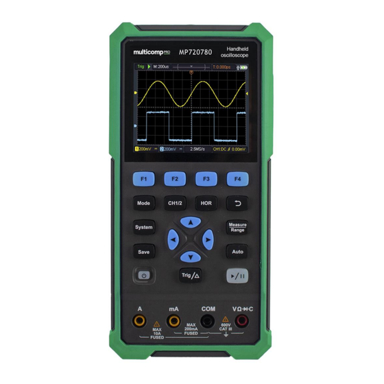
for this business informed about it, a repairing or replacement of the instrument will be arranged by us. 4. How to Use the Oscilloscope The Structure of the Oscilloscope Front Panel and Keys The front panel and keys of the oscilloscope are shown in Figure 4: Figure 4: Front Panel of the Oscilloscope Description: 1. - Page 9 3. Display area. 4. The F1 - F4 keys are multi-function keys. In each menu mode, press the corresponding key to select the corresponding menu item. 5. After pressing the HOR key, through the key , you can change the horizontal time base setting, and observe the change of the state information caused by it;...
-
Page 10: Side Panel
Side Panel Description: 1. Probe compensation: 3.3V/1kHz square wave signal output 2. Charging or USB communication interface 3. Bracket... -
Page 11: Introduction To The User Interface Of The Oscilloscope
Introduction to the User Interface of the Oscilloscope 1 2 3 Figure 5: Oscilloscope Interface Description: 1. The trigger status indicates the following information: Auto: Automatic mode. The waveform is being collected without triggering. Trig: A trigger has been detected and post trigger information is being collected. -
Page 12: Functional Check
10. Channel 2 waveform. 11. The icon indicates trigger-related information, including trigger channel, coupling mode, trigger type and trigger electrical level. For details, please refer to P19 Trigger System. 12. The current sampling rate. 13. The channel information reading indicates the voltage position of the corresponding channel. -
Page 13: Probe Compensation
the CH1 connector and insert it, then turn the probe to the right and tighten it. Connect the probe tip and ground clamp to the connector of the probe compensator. Please pay attention to the terminal polarity. The square terminal represents the signal output, and the round terminal represents the reference ground. -
Page 14: Probe Attenuation Coefficient Setting
2. Check the displayed waveform and adjust the probe until the compensation is correct. See Figure 0-2 and Figure 0-3. Overcompensation Correct compensation Under-compensation Figure 0-2: Display Waveform of Probe Compensation 3. Repeat the steps if necessary. Figure 0-3: Probe Adjustment Probe Attenuation Coefficient Setting The probe has a variety of attenuation coefficients, which will affect the vertical position factor of the oscilloscope. -
Page 15: Safe Use Of Probe
Note: The preset setting of the probe attenuation coefficient in the menu when the oscilloscope is delivered is 10X. Make sure that the attenuation switch setting value on the probe is the same as the probe attenuation coefficient option in the oscilloscope menu. -
Page 16: How To Use The Multimeter
Warning: To prevent electric shock when using the probe, please keep your fingers behind the safety ring on the probe body. To prevent electric shock when using the probe, do not touch the metal part of the probe head when the probe is connected to a voltage source. - Page 17 Description: 1. Measurement type indication: ------ DC voltage measurement ~ ACV ------ AC voltage measurement ------ DC current measurement ~ ACA ------ AC current measurement Resist ------ Resistance measurement Diode ------ Diode measurement Cont ------ On/Off measurement ------ Capacitance measurement 2.Range indication: Manual means manual range;...
-
Page 18: How To Use The Waveform Generator(Optional
6. How to Use the Waveform Generator (MP720781 & MP720783 only) The instrument can provide 4 basic waveforms, sine wave, square wave, ramp wave, pulse wave, and 8 arbitrary waveforms. Connect the output Press the Mode button to switch the instrument interface to the waveform generator function interface. -
Page 19: Troubleshooting
7. Troubleshooting 1. The oscilloscope cannot be turned on. It may be that the battery is completely exhausted. At this time, even if the oscilloscope is powered by the power adapter, the oscilloscope cannot be turned on. You need to charge the battery first, and do not turn on the oscilloscope. - Page 20 RUN/STOP. Check whether the trigger mode of the trigger mode menu is normal or single, and the trigger electrical level is out of the waveform range. If so, center the trigger electrical level or set the trigger mode to automatic. In addition, you can press Auto to automatically complete the above settings.
-
Page 21: Appendix
8. Appendix Appendix A: List of Accessories 1 USB cable 1 passive probes 1 crocodile clip cable (For MP720780/MP720782) 2 crocodile clip cable (For MP720781/MP720783) 1 set of multimeter probes 1 user manual 1 probe correction adjustment knife ... - Page 22 Do not use any abrasive chemical cleaning agent to avoid damaging the instrument or probe. Warning: Please make sure the instrument is dry before re-energizing to avoid electrical short circuit or personal injury caused by moisture. Charging and Replacement of Battery If you want to store the oscilloscope for a long time, it is recommended to fully charge the lithium battery before storing.
- Page 23 Note To avoid overheating of the battery during charging, the ambient temperature must not exceed the allowable value given in the technical specifications. Replacement of Lithium Battery Generally, the battery does not need to be replaced. However, when necessary, it can only be replaced by qualified personnel, and only lithium batteries of the same specification can be used.
Need help?
Do you have a question about the MP720780 and is the answer not in the manual?
Questions and answers