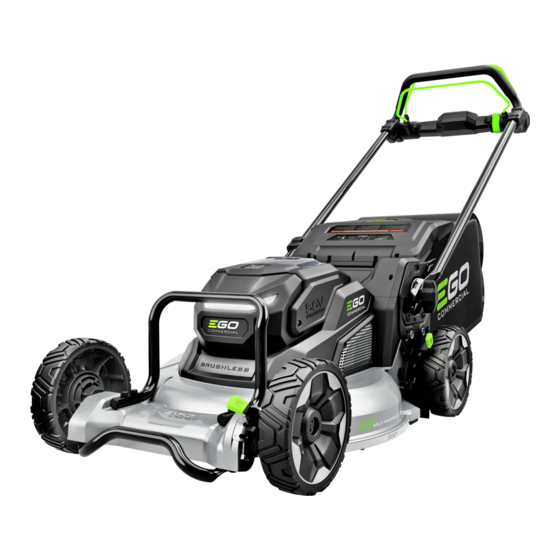
EGO LMX5300SP Troubleshooting Manual
Hide thumbs
Also See for LMX5300SP:
- Manual (297 pages) ,
- Operator's manual (164 pages) ,
- Repair manual line (101 pages)
Summary of Contents for EGO LMX5300SP
- Page 1 Troubleshooting based on the Mower Status Indicators Troubleshooting for LMX5300SP Lawn Mower Update Date: 2024/04/19...
-
Page 2: Table Of Contents
Table of Contents Contents Page Dashboard Display Mower Status Indicators according to the manual Wiring Diagram How to test the blade Motor & Self-propelled Motor How to test the BMS PCBA 7 ~ 10 How to test the MOSFET in the main PCBA 11 ~ 12 How to test the MOSFET in the Self-propelled PCBA 13 ~ 14... -
Page 3: Dashboard Display
Dashboard Display Mower Status Bluetooth Indicator Indicator Blade Speed Indicator... -
Page 4: Mower Status Indicators According To The Manual
Clean if necessary. 2. Slow down your stride when cutting. Flashing orange The mower is overloaded. 3. Raise the cutting height. 4. If above solutions do not work, please contact EGO service partners. Flashing Red/Green The mower electronics error. -
Page 5: Wiring Diagram
Wiring Diagram... -
Page 6: How To Test The Blade Motor & Self-Propelled Motor
How to test the blade Motor & Self-propelled Motor Steps: Self-propelled Motor Blade Motor a) Set the Multimeter function to “Diode measuring”. b) Measure the resistance between any of the two connectors. c) If any of the measurement are infinite, it means the circuit between the two connectors is an open circuit, the motor is damaged. -
Page 7: How To Test The Bms Pcba
How to test the BMS PCBA Step 1: a) Set the Multimeter function to “Diode measuring”. b) Contact the black pen pin to the POSITIVE contact of the terminal connected to the main PCBA and the red pen pin to POSITIVE contact of the terminal connected to the battery contact, then exchange the two pen pins for second... - Page 8 How to test the BMS PCBA Exchange the pens Terminal connected Terminals connected to the main PCBA to the battery contact...
- Page 9 How to test the BMS PCBA Step 2: a) Set the Multimeter function to “Buzzer measuring” . b) Contact the black pen pin to the NEGATIVE contact of the terminal connected to the main PCBA and the red pen pin to NEGATIVE contact of the terminal connected to the battery contact.
- Page 10 How to test the BMS PCBA...
-
Page 11: How To Test The Mosfet In The Main Pcba
How to test the MOSFET in the main PCBA Step 1: a) Set the Multimeter function to “Diode measuring” . b) Contact the red pen pin to the black electric contact of yellow connector. c) Contact the black pen pin to the three terminals of power connector separately and measure the voltage. - Page 12 How to test the MOSFET in the main PCBA Step 2: a) Keep the Multimeter function setting at “Diode measuring”. b) Contact the black pen pin to the red electric contact of yellow connector. c) Contact the red pen pin to the three terminals of power connector separately and measure the voltage.
-
Page 13: How To Test The Mosfet In The Self-Propelled Pcba
How to test the MOSFET in the Self-propelled PCBA Step 1: a) Set the Multimeter function to “Diode measuring” . b) Contact the red pen pin to the black electric contact of yellow connector. c) Contact the black pen pin to the three terminals of power connector separately and measure the voltage. - Page 14 How to test the MOSFET in the Self-propelled PCBA Step 2: a) Keep the Multimeter function setting at “Diode measuring”. b) Contact the black pen pin to the red electric contact of yellow connector. c) Contact the red pen pin to the three terminals of power connector separately and measure the voltage.
-
Page 15: Troubleshooting
Troubleshooting Fault Possible cause Steps Troubleshooting Action The mower does not activate The batteries are defective Examine the batteries Replace the batteries (Mower status indicator and blade speed indicator do not come on) The main PCBA is defective Press the power button, two battery indicators shine green. - Page 16 Troubleshooting Fault Possible cause Steps Troubleshooting Action The blade does not start The handle folded hall assembly is Press the LED light button, the LED light comes on. Replace the handle folded hall ((Mower status indicator flashes green, defective or the magnetic block in The mower has no self-propel function assembly or the magnetic block blade speed indicator comes on)
- Page 17 Troubleshooting Fault Possible cause Steps Troubleshooting Action The mower does not self- The self-propelled PCBA is defective Examine the self-propelled PCBA refer to “How to test the self- Replace the self-propelled PCBA propel propelled PCBA ” section (Mower status indicator shines green, The self-propelled trigger hall assembly is Use a new fixing Block Assembly to test the self-propelled...
- Page 18 (Note: A device ID needs to be written into the Bluetooth PCBA by EGO Diagnostic Tool. Otherwise, the mower still can’t connect to EGO APP. ) Switch PCBA assembly is defective Use a good top switch box assembly to examine the...


Need help?
Do you have a question about the LMX5300SP and is the answer not in the manual?
Questions and answers