Advertisement
Table of Contents
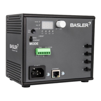
Basler Light Controller 4C-1.25A-
84W-24V#
The Basler Light Controller 4C-1.25A-84W-24V allows you to use any
Light
as well as any other light device in your environment.
If you directly connect the lights to the controller, you can specify the output current supplied
to the light which in turn controls the brightness. Alternatively, you can use a camera as an
external trigger source allowing you to turn the light on or off.
Specifications#
General
Specifications#
Input Voltage
Power Consumption
Driver Method
Brightness Control Method
Communication Port
Number of Channels
External Trigger Response
Protection
Channel 1–4 Output Voltage (Rate)
Channel 1–4 Maximum Output Current (per
Channel)
12 V Output Voltage (Rate)
2200001189
Basler Light Controller 4C-1.25A-84W-24V
100–240 VAC
120 W (typically)
Constant-current system
Manual (10 mA – 1.25 A) or via current limit
100/10 Mbps Ethernet (TCP/UDP IP)
4
<50 µs
Short circuit protection
Over temperature protection
Current limit circuit
8–24 VDC
1.25 A
12 VDC
Basler Standard
Advertisement
Table of Contents

Related Manuals for Basler 4C-1.25A84W-24V


Summary of Contents for Basler 4C-1.25A84W-24V
- Page 1 Basler Light Controller 4C-1.25A- 84W-24V# 2200001189 The Basler Light Controller 4C-1.25A-84W-24V allows you to use any Basler Standard Light as well as any other light device in your environment. If you directly connect the lights to the controller, you can specify the output current supplied to the light which in turn controls the brightness.
-
Page 2: Specifications
Basler Light Controller 4C-1.25A-84W-24V 12 V Maximum Output Current 0.5 A Max. Output Power 30 W per channel; 84 W total (incl. channel 1–4 and 12 VDC Output) Ripple Current <15 % @ 24 VDC/1.25 A External Trigger Input 12–24 VDC; External On/Off trigger with High/Low... - Page 3 Temperature and Humidity# Temperature during operation 0–40 °C (32–104 °F) Humidity during operation 30–85 %, relative, non-condensing Storage temperature -20–60 °C (-28–140 °F) Storage humidity 20–85 %, relative, non-condensing Electrical Requirements# Power must be supplied to the controller via the 3-pin C14 connector labeled AC INLET. Voltage Requirements Power Consumption 100–240 VAC...
- Page 4 250 VAC min Controller-to-Light Cable# The maximum cable length is 8 m. For optimum performance and ease-of-use, Basler recommends using the following cables: • BLC-BSL connect cable M8, 2m (order number: 2200001192) • BLC-BSL connect cable M8, 5m (order number: 2200001193) •...
- Page 5 Part Function LEDs Indicates controller operation (see LEDs details) Display Used to configure the controller in manual mode LEDs# The controller has the following LEDs: Colors and Meaning A/mA Green: Current unit is set to A. Off: Current unit is set to mA. Green: Trigger signal is high (1).
- Page 6 Function Light + Not connected Light - 7-Pin PCB Terminal Block Connector# Function 12 VDC - 12 VDC + Common Channel 4 Channel 3 Channel 2 Channel 1 Ethernet Connector# Precautions# WARNING – Fire Hazard / Electric Shock Hazard • •...
-
Page 7: Installation
• WARNING – Electric Shock Hazard • • WARNING – Fire Hazard • • NOTICE – Improper handling may damage the product. • • • • NOTICE – Product Failure • • • • • NOTICE – Incorrect voltage may damage the product. •... -
Page 8: Operation
Mounting the Controller On a DIN Rail# To mount the controller on a DIN rail: 1. Tilt the controller to hook over the DIN rail. 2. Push down on the controller to fasten it to the DIN rail. Connecting the Controller and the Light# Connect the cables of the lights using the Light + and Light - pins of the 3-Pin JST-SMR... - Page 9 2. Press CHL SEL to select the channel you want to configure. 3. Configure how you want to operate the selected channel. You can configure the following modes for each channel: a. OFF mode: Turns off the light and disables the output of the selected channel.
- Page 10 c. Trigger follow mode: In this mode, the light is controlled by a trigger signal, so you can use it as a strobe light. The brightness can range from 0 mA to the overdrive limit. d. Trigger start mode: In this mode, the light is turned on by a trigger signal and stays on for a certain amount of time, so you can use it as...
- Page 11 The overdrive limit defines the maximum current the controller may supply in overdrive mode, which allows brightness levels above 100 %. Basler recommends using overdrive in strobe mode only, where you must also define the duty cycle. Check the documentation of your light to find out about its maximum allowed overdrive and duty cycle.
- Page 12 NOTICE – Currents outside of the specified output current range may damage the LEDs of the light. You must supply the light with the correct output current, overdrive, and duty cycle as provided in the documentation of your light. If you don't adhere to these values in the configuration of your controller, the LEDs of your light might be damaged.
- Page 13 Configuring the Strobe Time# In Trigger Start mode, you can configure the duration ("ON time") of the strobe light. To do 1. Select the Trigger Start mode. 2. Press the BRT button three times until the ON time is displayed. 3.
- Page 14 Operating the Controller in Ethernet Mode via Interface# To configure your controller via web interface: 1. Connect the controller to a host computer using an Ethernet cable. 2. Switch the mode selector to ETHERNET. 3. Make sure your Ethernet port on the host computer is set to the same IP range and subnet mask as the controller: •...
- Page 15 Configuring IP Address and LAN Settings# On the Controller Info page, you can see all defined settings regarding LAN status and versions. To configure the LAN settings, open the LAN Settings page: You can configure the following settings: • DHCP On: Choose this option if you're using a DHCP server in your network. The DHCP server automatically assigns IP addresses.
- Page 16 • DHCP Off: Choose this option if you want to configure the IP address manually. Make sure that you use an IP address which isn't used by any other device in the same network. It's common to keep the first three numbers for all devices in the same network and change only the last number.
-
Page 17: Configuring Your
The current limit defines the maximum current the controller may supply and therefore equals 100 % brightness. Check the documentation of your light to find out about its maximum allowed current. Then, configure the maximum current limit in the Max field of the desired channel and click Set. - Page 18 You can configure the following modes for each channel: 1. OFF mode: Immediately turns off the light and disables the output of the selected channel. 2. ON mode: Turns the light on permanently. In this mode you can only configure the brightness.
- Page 19 3. Trigger follow mode: In this mode, the light is controlled by a trigger signal, so you can use it as a strobe light. The brightness can range from 0 mA (i.e. 0 %) to the overdrive limit (i.e. 100 %). 4.
- Page 20 Command Action Return (ASCII) Function (x) Values Trigger Start MODx? Read CHx:My<CR><LF> Reads the Mode of channel x (x = 1–4) CHx:yyyy CHx:y<CR><LF> Sets < 1 A: 5 the brightness (current mA per mA) of channel x step (x = 1–4, yyyy = 10–1250) ≧...
- Page 21 Command Action Return (ASCII) Function (x) Values CLx? Read CHx:Iy<CR><LF> Reads the Output Current ILEDx? Limit of channel x (x = 1– OLDx:yyyy CHx:Oy<CR><LF> Sets the Output < 1 A: 5 Overdrive Current Limit mA per (x = 1–4, yyyy = 10–1250) step ≧...
Need help?
Do you have a question about the 4C-1.25A84W-24V and is the answer not in the manual?
Questions and answers