Advertisement
Quick Links
CONFIDENTIAL INFORMATION
OF BASLER ELECTRIC COMPANY, HIGHLAND, IL.
IT IS LOANED FOR CONFIDENTIAL USE, SUBJECT
TO RETURN ON REQUEST, AND WITH THE
MUTUAL UNDERSTANDING THAT IT WILL NOT BE
USED IN ANY MANNER DETRIMENTAL TO THE
INTEREST OF BASLER ELECTRIC COMPANY.
BASLER ELECTRIC,
INTRODUCTION
The AVC63-4A Voltage Regulators are designed
for use on 50/60 Hz brushless generators. The
regulator
includes
frequency
overexcitation shutdown, a solid-state build-up
circuit, and EMI filtering.
ELECTRICAL SPECIFICATIONS
Dc Output Power:
4 Adc at 63 Vdc (252W) maximum continuous,
7 Adc at 100 Vdc (700W) forcing one minute
(at 120 Vac input).
9 Adc at 134 Vdc (1206W) forcing for 10
seconds (at 153 Vac input).
Exciter Field Dc Resistance:
15 ohms, minimum; 100 ohms maximum.
Ac Power Input:
Operating range: 95 Vac to 139 Vac, ±10%,
Single phase, 50/60 Hz, Burden: 450 VA.
Sensing Input:
95-139 Vac, ±10%, or 190-277 Vac, ±10%,
single phase, 50/60 Hz.
Regulation Accuracy:
Better than ±1.0% no load to full load.
Response Time:
Less than 1.5 cycles for ±5% change in sensing
voltage.
EMI Suppression:
Internal electromagnetic interference filter (EMI
filter).
Overexcitation Shutdown:
Field voltage shuts down after time delay if
exciter field voltage exceeds 95 Vdc, ±5% (See
Overexcitation Shutdown for inverse time delay
curve and description).
Voltage Build-up:
Internal provisions for automatic voltage build-up
from generator residual voltages as low as 6
Vac.
Power Dissipation:
15 Watts maximum.
Terminations:
1/4 inch "Fast-On" terminals.
PHYSICAL SPECIFICATIONS
Operating Temperature:
-25 C (-13 F) to +60 C (+140 F).
Storage Temperature:
-40 C (-40 F) to +85 C (+185 F).
Vibration:
Withstands 1.2 Gs at 5 to 26 Hz; 0.036" double
amplitude at 27 to 52 Hz; and 5 Gs at 53 to 1000
Hz.
Shock:
Withstands up to 20 Gs in each of three mutually
perpendicular axes.
Weight:
10 oz. (0.28 kg) Net.
FUSES
Although the AVC63-4A has an internal fuse, it is
recommended that fuses with high interruption
capability be installed per the interconnection
INSTRUCTION MANUAL
VOLTAGE REGULATOR
Part Number: 9 2858 00 100
BOX 269,
diagram to protect wiring from faults before the
regulator.
AVC63-4A (internal fuse).
"piggyback" to the orginal fuse.
compensation,
Outline Diagrams.
Fuse
interconnection diagrams to avoid inter-
rupting the field current.
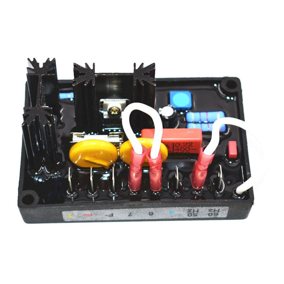
AVC63-4A Outline Diagram (Top View)
AVC63-4A Outline Diagram (Side View)
V/HZ "CORNER FREQUENCY" SELECTION
AND ADJUSTMENT
For 60 Hz systems, the regulator is preset at the
factory for a 55 Hz "corner frequency". For 50
Hz systems, a 45 Hz "corner frequency" is
achieved
terminals Hz1 and Hz2.
The corner frequency can be adjusted by the UF
ADJ rheostat on the AVR. Clockwise rotation
results in raising the corner frequency (shifting
the curve to the right). To set the UF rheostat:
1. Adjust the UF Rheostat fully CCW.
2. Start the generator and set at rated voltage.
FOR
Model: AVC63-4A
HIGHLAND, IL 62249
A spare fuse is included with the
It is mounted
Refer to the
NOTE
must
be
installed
per
by
connecting
a
jumper
Publication:
© 1997, Basler Electric Co., Highland, IL 62249
First Printing June 1994
Revision: D
ECA: 16300
PHONE 618/654-2341
3. Adjust the generator frequency to the desired
kneepoint frequency.
4. Slowly adjust the UF ADJ rheostat clockwise
(CW) until the generator voltage just begins to
decrease.S
the
Frequency Compensation Curves
OVEREXCITATION SHUTDOWN
Overexcitation
shutdown
removes the output power if the exciter field
voltage exceeds 95 Vdc. If exciter field voltage
exceeds 95 Vdc ±5%, the regulator automatically
removes field current, after a time delay. The
time delay is inversely proportional to the
magnitude of the detected overvoltage condition.
At 134 Vdc, the field voltage is removed after
approximately 10 seconds.
following figure.
Typical Time Delay Characteristic Curves
After output power is removed, the regulator can
be reset by decreasing the input voltage to less
than 6 Vac for a minimum of 2 seconds; this may
be accomplished by stopping the prime mover or
by interrupting the regulator input with a reset
switch.
STABILITY ADJUST RHEOSTAT (STAB)
An internal screwdriver adjustable potentiometer
provides adjustment to the response rate of the
generator output voltage to a change in load.
Clockwise rotation of this adjustment provides an
increase in the response time and therefore
decreases the amount of voltage overshoot
(increased stability). Counter-clockwise rotation
across
of this adjustment provides a decrease in the re-
sponse time (faster response time) and therefore
increases the amount of voltage overshoot
(decreased stability).
OPERATION
The following system operation procedures
provide instructions for adjusting the AVC63-4A
voltage regulator.
9 2858 00 990
September 1997
FAX 618/654-2351
is
included
that
Refer to the
Symptoms resulting from a
Advertisement

Subscribe to Our Youtube Channel
Related Manuals for Basler AVC63-4A


Summary of Contents for Basler AVC63-4A
- Page 1 OPERATION results in raising the corner frequency (shifting the curve to the right). To set the UF rheostat: Although the AVC63-4A has an internal fuse, it is The following system operation procedures recommended that fuses with high interruption provide instructions for adjusting the AVC63-4A 1.
- Page 2 60 Hz. V1 and V2 are connnected together. than ±1.0% no-load to full-load. If regulation is 3. Item not supplied by Basler Electric. not within this range, perform the following steps: 3. Ensure the voltage regulator is correctly 4. For 120 V Nominal sensing, make no connected to the generator system.
- Page 3 H z 1 H z 2 D2619-20 08-22-97 Interconnection Diagram, 120/240 V Nominal, 1-Phase, 3-Wire AVC63-4A D 2 6 1 9 - 1 7 0 8 - 2 2 - 9 7 Interconnection Diagram, 120/208 V Nominal, 3-Phase, 4-Wire, Wye Connection...
Need help?
Do you have a question about the AVC63-4A and is the answer not in the manual?
Questions and answers