Table of Contents
Advertisement
Quick Links
Advertisement
Table of Contents

Related Manuals for Shinko SAF Series


Summary of Contents for Shinko SAF Series
- Page 1 PULSE ISOLATOR SAF SERIES SAFI INSTRUCTION MANUAL...
-
Page 2: Safety Precautions
• Any unauthorized transfer or copying of this document, in part or in whole, is prohibited. • Shinko Technos CO., LTD. is not liable for any damage or secondary damage(s) incurred as a result of using this product, including any indirect damage. - Page 3 Caution This instrument is intended to be used under the following environmental conditions (IEC61010-1): Overvoltage category , Pollution degree 2 Ensure the mounting location corresponds to the following conditions: • A minimum of dust, and an absence of corrosive gases •...
-
Page 4: Table Of Contents
Characters used in this manual Indication Number, Indication Alphabet Indication Alphabet means that no character is indicated (unlit) on the display. CONTENTS Page 1. Model ............................5 1.1 Model ............................ 5 1.2 How to Read the Model Label ................... 5 2. -
Page 5: Model
1. Model 1.1 Model SAFI - 0 Series name: SAF Open collector Voltage pulse Input Line driver Contact switch Open collector Output 5 V voltage pulse 12 V voltage pulse 100 to 240 V AC Power supply 24 V AC/DC (Example) SAFI-000-0 Input frequency: 800 Hz, Scaling: 0 to 800 Factory default: Input frequency: 9999 Hz Scaling: 0 to 800... -
Page 6: Mounting
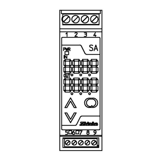
3. Mounting 3.1 External Dimensions (Scale: mm) DIN rail 22.5 (Fig. 3.1-1) 3.2 Mounting to and Removal from the DIN Rail Caution • Mount the DIN rail horizontally. • To remove this instrument, a flat blade screwdriver is required for pulling down the lever. -
Page 7: Wiring
Release lever (Fig. 3.2-1) Mounting (Fig. 3.2-2) Removal 4. Wiring Warning Turn the power supply to the instrument off before wiring. Working on or touching the terminal with the power switched on may result in severe injury or death due to electrical shock. 4.1 Recommended Ferrules When using ferrules, use the following recommended ferrules and crimping pliers made by Phoenix Contact GMBH &CO. -
Page 8: Terminal Arrangement And Circuit Configuration
4.2 Terminal Arrangement and Circuit Configuration Insulation circuit Input Output Output circuit circuit Input Power supply for sensor Display/Setting Fixed voltage Power key circuit circuit 12V Power supply circuit Input connection example Open collector Voltage pulse Line driver Contact switch (Fig. -
Page 9: Key Operation Flowchart
5. Key Operation Flowchart Power ON Warm-up indication (Approx. 2 sec.) Run mode Press the SUB-MODE key and the (in that order) together. Setup mode Set value lock Press the key. Frequency type/unit Press the key. Frequency One-shot high limit value output pulse width Press the... -
Page 10: Setup
6. Setup Setup should occur before using this unit according to the user’s specifications (setting the Frequency type/unit, Frequency high limit value, Output 0% value, Output 100% value, One-shot output pulse width, output Normal/Reverse, etc.). If the user’s specifications are the same as the default value of this instrument, or if setup has already been completed, it is not necessary to set up the instrument. -
Page 11: Basic Operation Of Setup
6.2 Basic Operation of Setup Setup is conducted in Setup mode. To enter Setup mode, press the SUB-MODE key and key (in that order) together in Run mode. (Fig. 6.2-1) To set (select) each item, use the key, and register the value with the key. -
Page 12: When Using This Unit As A Standard Pulse Isolator
Output 0% value Sets the value (indicated on the Input Display) at 0% output. Setting range: -1999 to Output 100% value Output 100% value 9999 Sets the value (indicated on the Input Display) at 100% output. Setting range: Output 0% value to 9999 Decimal point place No decimal point Selects the decimal point place. -
Page 13: Unit Operation
Output waveform If One-shot output pulse width is set to 0 ms, input and output will be the same pulse width. Output signal delay is maximum 15 When One-shot output pulse width is set to a value (1 to 400 ms), and if a pulse is entered, outputs “one-shot output pulse”... -
Page 14: Specifications
• Indication when input value is 10000 or more When DC current or voltage input is selected: For the indication of 10000 or more, the lower 4 digits of input value are flashing. (e.g.) Indication of 10020 Flashes. • Indication when pulse is absent When pulse is absent, 0 (zero) flashes. -
Page 15: Troubleshooting
Performance Reference accuracy: Within 0.1% (At 23 of ambient temperature) Display accuracy: Within Reference accuracy 1 digit Response time: 15 s or less (For open collector output, rising time delays depend on load.) Input – Output – Power: 10 M Insulation resistance: or more, at 500 V DC Input –... -
Page 16: Key Operation
• Model ......………. SAFI-0 • Serial number …....No. xxxxxx In addition to the above, please let us know the details of malfunction, or discrepancy, and the operating conditions. SHINKO TECHNOS CO., LTD. OVERSEAS DIVISION Head Office: 2-5-1, Senbahigashi, Minoo, Osaka, 562-0035, Japan [URL] https://shinko-technos.co.jp/e/...
Need help?
Do you have a question about the SAF Series and is the answer not in the manual?
Questions and answers