Table of Contents
Advertisement
Quick Links
G574U OWNER'S MANUAL CONTENTS
1. INTRODUCTION ...........................................................................
2. SAFETY PRECAUTIONS ..............................................................
3. WARNING LABEL POSITION ........................................................
4. LIST OF PARTS ............................................................................
5. ASSEMBLE THE PRODUCT ......................................................... 11
STEP 1 Install the Seat Post .............................................................. 11
STEP 2 Install the Console and Console Mast .................................. 12
STEP 3 Install the Handlebar ............................................................ 13
STEP 4 Install the Seat and Pedal ..................................................... 14
STEP 5 Move the Bike in Place ........................................................
STEP 6 Level the Bike ....................................................................... 16
STEP 7 Install the Power Cord........................................................... 17
STEP 8 Seat Horizontal Position Adjustment ..................................... 18
STEP 9 Seat Height Adjustment ........................................................ 19
STEP 10 Essential Functions Guide .................................................. 20
STEP 11 MAINTENANCE Circuit Breaker ......................................... 21
6. UNDERSTAND THE G574U LCD DISPLAY ..................................
DISPLAY Overview ...........................................................................
DISPLAY Console Panel ...................................................................
DISPLAY Windows Display ................................................................ 23
DISPLAY Specifications ..................................................................... 23
DISPLAY Button Function ............................ ..................................... 24
7. OPERATE THE PRODUCT ........................................................... 26
OPERATION Safe Operating Area ..................................................... 26
OPERATION Proper Workout Position ............................................... 27
OPERATION Safely Get On/Off ......................................................... 28
OPERATION Start Screen ................................................................. 29
OPERATION <GO> Mode ................................................................ 29
OPERATION User Setting Procedure ................................................ 29
OPERATION Workout Programs ....................................................... 32
OPERATION During Exercise ...........................................................
OPERATION Cool Down ..................................................................
OPERATION Stop/Pause Exercise ..................................................
OPERATION Workout Summary .......................................................
OPERATION Idle Mode ....................................................................
OPERATION Auto Power Off Function ..............................................
OPERATION User Parameter Setting ...............................................
8. ABOUT HEART RATE DETECTION .............................................
HEART RATE Telemetry ...................................................................
HEART RATE Contact ......................................................................
3
4
8
9
15
22
22
22
38
38
38
38
39
39
40
42
42
42
Advertisement
Table of Contents

Subscribe to Our Youtube Channel
Related Manuals for SportsArt Fitness G574U


Summary of Contents for SportsArt Fitness G574U
-
Page 1: Table Of Contents
STEP 9 Seat Height Adjustment ............19 STEP 10 Essential Functions Guide ..........20 STEP 11 MAINTENANCE Circuit Breaker ......... 21 6. UNDERSTAND THE G574U LCD DISPLAY ........DISPLAY Overview ................DISPLAY Console Panel ..............DISPLAY Windows Display ..............23 DISPLAY Specifications .............. - Page 2 G574U OWNER’S MANUAL CONTENTS 9. GUIDELINES FOR EXERCISE ............. 10. Micro Inverter MI-250 ..............44 MICRO INVERTER Important Safety Instructions ......44 MICRO INVERTER Cautionary Messages ......... 44 MICRO INVERTER Electronic Specifications ........46 MICRO INVERTER Circuit Board & Product Settings ......47 11.
-
Page 3: Introduction
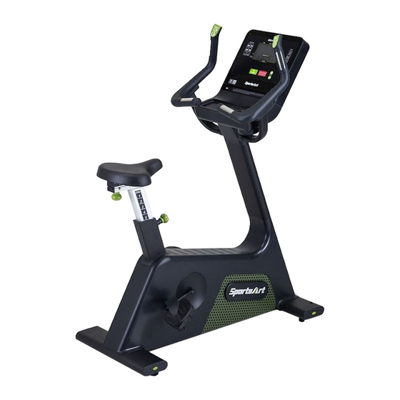
1. INTRODUCTION Congratulations on the purchase of a high quality SportsArt product, the G574U upright exercise cycle. Constructed of high quality materials and designed for years of reliable performance, this product was made for full commercial use. Before this product is assembled or operated, we recommend that you familiarize yourself with this manual. -
Page 4: Safety Precautions
2. SAFETY PRECAUTIONS This product was designed and built for optimum safety. However certain precautions apply during the use of this product. Please note the following safety precautions: ● To reduce the risk of personal injury, read and understand all the instructions before using this product. - Page 5 2. SAFETY PRECAUTIONS (CONTINUED) ● This product is not intended for use by persons (including children 12 or younger) with reduced physical, sensory, or mental capabilities, or by people who are otherwise deficient in product knowledge or experience. If such people use this product, they should be given training and be supervised at all times by someone responsible for their safety.
- Page 6 2. SAFETY PRECAUTIONS (CONT.) ● This equipment has been tested and found to comply with the limits for a Class B digital device, pursuant to part 15 of the FCC Rules. These limits are designed to provide reasonable protection against harmful interference in a residential installation.
- Page 7 2. SAFETY PRECAUTIONS (CONT.) MARKINGS CAUTION: ● Read instruction manual before using. ● Do not let children on or near the product. WARRING: ● Heart rate monitoring system may be inaccurate. ● Over exercise may result in serious injury or death. ●...
-
Page 8: Warning Label Position
3. WARNING LABEL POSITION If you are in French-speaking areas in North America, display the warning label on console panel as shown below, or in an obvious location that is visible to the user. NOTE: The label is available exclusively in French-speaking areas in North America. -
Page 9: List Of Parts
4. LIST OF PARTS A4 A5 Assembly Parts Name Qty. No. Name Qty. A1 Main frame Right handlebar A2 Console Saddle A3 Console mast Seat post A4 Left handlebar cover A10 Left pedal A5 Right handlebar cover A11 Right pedal A6 Left handlebar A12 Power cord... - Page 10 4. LIST OF PARTS (CONTINUED) Components on the Product Name Specification Notes Inner hex screw M8*P1.25*L25 Flat washer D13*d6*t2.0 Inner hex screw M6*P1.0*L15 Flat washer D13*d6*t2.0 Toothed washer D20*d6.2*t2.0 Mushroom top inner hex screw Class 10.9 Alloy steel Toothed washer DI-P063 D18*d8.5*t2.0*19T Spring washer M8*P1.25*L15...
-
Page 11: Assemble The Product
5. ASSEMBLE THE PRODUCT STEP 1 Install the Seat Post Pull the lock knob, and install the seat post (A9) into the seat post housing on the main frame. (If you cannot install the seat post in place, please check if the lock knob is fully turned as shown.) Release the lock knob and install the plastic piece on the seat post to the post housing with the screws. -
Page 12: Step 2 Install The Console And Console Mast
STEP 2 Install the Console and Console Mast (a)Remove the maintenance cover (50) and pre-installed screws (38). Insert the console mast into the main frame (A1) from top to bottom. Make sure the tabs in area (a) are snapped and locked into the console mast (A3), then secure the console mast (A3) to the main frame (A1) with screws (38). -
Page 13: Step 3 Install The Handlebar
STEP 3 Install the Handlebar (a) Connect the cables from left & right handlebars (A6)(A7) to the cables from the console mast (A3), then arrange all the cables and tuck them neatly into the opening. (b) Secure left & right handlebars (A6)(A7) to the console mast (A3) with pre-installed screws (40). -
Page 14: Step 4 Install The Seat And Pedal
STEP 4 Install the Seat and Pedal (a) Bring the saddle (A8) into alignment and secure it to the seat post with screws (41). (b) Use the tool enclosed with the product to secure the left/right pedals (A10/A11) to the crank on the main frame, please note that pedal spindle threads are different from left side and right side. -
Page 15: Step 5 Move The Bike In Place
STEP 5 Move the Bike in Place Please follow the instructions as below to move the bike in place. (1) Stand in front of the bike, with one foot against the front wheel, then tilt the bike by the handlebars. (2) Lift the bottom tube behind the bike , then tilt the bike for moving. -
Page 16: Step 6 Level The Bike
STEP 6 Level the Bike Please apply force to the end of the bike to check if the leveling knob is stable on the ground. If not, adjust the levelers as follows: (a) Loosen the leveling knob. (b) Rotate the leveling knob downward to the ground to make it steady. (c) Tighten the leveling knob. -
Page 17: Step 7 Install The Power Cord
STEP 7 Install the Power Cord (1)Remove the screw (43) from the base of the bike. (2)Insert the power cord plug into the connector on the product. (3)Plug the power cord (A12) into the outlet and secure the power cord plug into place with the removed screw (43). -
Page 18: Step 8 Seat Horizontal Position Adjustment
STEP 8 Seat Horizontal Position Adjustment (a) Loosen the fore-and-aft tension knob by turning the knob counterclockwise, then move the seat forward or back to the desired position. (b) Tighten the tension knob by turning clockwise once you have reached the desired position. -
Page 19: Step 9 Seat Height Adjustment
STEP 9 Seat Height Adjustment Turn the seat height pop-pin counterclockwise and pull out on the pin to release it from its current preset location. Raise or lower the seat to the desired height, then gently release the pop-pin and turn clockwise to secure. -
Page 20: Step 10 Essential Functions Guide
STEP 10 Essential Functions Guide RESISTANCE: Adjust the weight or force you need to place on the pedals to move them. -
Page 21: Step 11 Maintenance Circuit Breaker
STEP 11 MAINTENANCE Circuit Breaker (a)A circuit breaker is an automatically operated electrical switch designed to protect an electrical circuit from damage caused by overcurrent/overload or short circuit. A spring located under the push button causes the button at area D to lift up and the breaker to trip as shown. (b)After the fault is repaired by qualified technicians, press the push button to reset circuit breaker to resume normal operation as shown. -
Page 22: Understand The G574U Lcd Display
6. UNDERSTAND G574U LCD DISPLAY DISPLAY Overview In this chapter, you will learn how to use and set up the console of your bike. Please read the entire manual prior to using the bike to get the most efficient and enjoyable workout. -
Page 23: Display Windows Display
DISPLAY Window Display Description Display the data of your heart rate value. (Displayed when BOTH HANDS hold on the sensor.) Display the pedal revolutions per minute. (RPM). Display the messages or the illustration. Display the total time covered or the remaining time. Display the cumulative number of Watt-hour To GRID. -
Page 24: Display Button Function
DISPLAY Button Function Illustration Description The button has two functions : (1) Skip the user input, program selection, and start train- ing instantly. (2) After the parameter settings are complete, press the key to confirm your selection. Press the button to stop/pause your workout program; Hold down to go back to start screen and reset it to fac- tory settings. - Page 25 DISPLAY Button Function (Cont.) Illustration Description Press this key to select one of an almost endless num- ber of randomly generated workout programs. Each key press, the console will randomly generate a different pro- gram.The notification LED will stay lit when selected. Press this key to enter FIT TEST mode.
-
Page 26: Operate The Product
7. OPERATE THE PRODUCT OPERATION Safe Operating Area (a) Safety clearance required as shown below. Do not allow people to be near this area when operating. (b) Noise emission under load is higher than without load. -
Page 27: Operation Proper Workout Position
OPERATION Proper Workout Position (a) A good riding posture is illustrated below. (b) Always follow the directions for use and safety instructions given by the manufacturer. Over exercise or improper workout position may result in serious injury (c) Hold onto the handlebar while getting off the bike from left/right side. (d) This product is intended to build your leg and cardiovascular strength. -
Page 28: Operation Safely Get On/Off
OPERATION Safely Get On/Off Getting on the bike: Always be cautious when getting on the bike. Wait to get on until the pedals have come to a complete stop. Getting off the bike: Always be cautious when getting off the bike. Always wait until the pedals have come to a complete stop before taking your feet off of the pedals and dismounting. -
Page 29: Operation Start Screen
OPERATION Start Screen Step on the pedal to start the machine. After starting, you will hear the BEEP sound and see the start screen. OPERATION <GO> Mode GO mode is preset based upon a user that is 35 years 35 years old and weighs 75 kilograms (165 pounds). - Page 30 OPERATION User Setting Procedure (Continued) Parameter Window Description Setting a TIME workout goal: Select <TIME> as your workout goal, the <TIME> notification LED light will stay on and then proceed to time set- tings. The range is 5 - 300 minutes with the default of 30 minutes.
- Page 31 OPERATION User Setting Procedure (Continued) Parameter Window Description Setting a Watt-hour TO GRID work- out goal: Select < Watt-hour TO GRID > as your workout goal, the < Watt-hour TO GRID > notification LED light will stay on and then proceed to Watt-hour TO GRID settings.
-
Page 32: Operation Workout Programs
OPERATION Workout Programs You can choose the desired program from the PROGRAM menu located at the bottom left corner of the display. MANUAL: The general mode. Users can set their desired workout program.The resistance can be adjusted according to your own preference. PLATEAU: This program is designed to simulate a workout on a plateau, the change in resistance is shown in the picture below. - Page 33 OPERATION Workout Programs (Continued) FIT TEST This program measures your fitness level using a default time goal and a few simple tests. 1. Select this mode, then simply enter your gender, age, and weight before you start your workout. 2. Start fitness testing after the words “STARTING TEST” pop up. 3.
- Page 34 OPERATION Workout Programs (Continued) a. Each exercise stage lasts for 3 minutes. b. Tips for each exercise stage: Stage 1: the default watt load is 25W, and the watt load for next stage depends on the heart rate measured at last 15 sec. of stage 1. For example, if the heart rate measured at last 15 sec.
- Page 35 OPERATION Workout Programs (Continued) Percentile Values For Maximal Aerobic Power(ml.kg .min )--Men Percentile 20-29 30-39 40-49 50-59 60+ 51.4 50.4 48.2 45.3 42.5 48.2 46.8 44.1 41.0 38.1 46.8 44.6 41.8 38.5 35.3 44.2 42.4 39.9 36.7 33.6 42.5 41.0 38.1 35.2 31.8...
- Page 36 OPERATION Workout Programs (Continued) (3) The following is an example of calculating VO2MAX for a 40-year-old, 62kg male: a. The heart rate ≧ ((220-age)×0.85)-10 in the last min. of stage 3. The exercise ends. The watt load and heart rate for each stage are pre- sented in the following table.
- Page 37 OPERATION Workout Programs (Continued) WT LOSS , CARDIO: The programs take control of resistance, keeping your heart rate within the target zone. (1) Before entering this mode, press <WT LOSS/CARDIO> key to toggle between WT LOSS and CARDIO. The words “♥ 120” shown on the display represent WT LOSS mode, and the words “♥...
-
Page 38: Operation During Exercise
OPERATION During Exercise During exercise, you can switch to a different program using the same WORKOUT GOAL(TIME/DISTANCE/CALORIES/Watt-hour TO GRID) by pressing a different program key. Please note it is not allowed to switch directly in the situation as below, and the window will display the message ”... -
Page 39: Operation Idle Mode
OPERATION Idle Mode The machine will turn into power saving mode when there is no stepping on the pedal or no button presses for 50 seconds. The window will display “----” and continue to flash. To restart the machine, please step on the pedal or press any button to return to start screen. -
Page 40: Operation User Parameter Setting
OPERATION User Parameter Setting Hold the < RESISTANCE - > for 3 seconds to enter the user parameter setting procedures; press the <STOP> key at any time to return to the start screen. Please refer to the following setting procedures: (1) Metric System / Imperial Units Setting The window will display KM or MILE, press <... - Page 41 OPERATION User Parameter Setting (Continued) (6) Product Serial Number The Window will show the message of “S/N xxxxxxxx” (as shown below), press < GO/ENTER > and go to the next step. ※ The number “1234567” in the picture represents the machine serial number.
-
Page 42: About Heart Rate Detection
8. ABOUT HEART RATE DETECTION Heart rate detection functions are selected at the time of purchase. Not every product has every type of heart rate detection. The following explains factors that influence the performance of two of the most common types of heart rate detection devices. -
Page 43: Guidelines For Exercise
9. GUIDELINES FOR EXERCISE HOW HARD SHOULD I EXERCISE? Studies show that to benefit from aerobic exercise, people need to maintain a certain heart rate during their workouts. Your heart rate training zone depends on your age and fitness level. The darkened area in the chart to the right represents the recommended heart rate training zone for people of various ages. -
Page 44: Micro Inverter Mi-250
10. MICRO INVERTER MI-250 MICRO INVERTER Important Safety Instructions CAUTION These servicing instructions are for use by qualified personnel only. To re- duce the risk of electric shock, do not perform any servicing other than that specified in the operating instructions unless you are qualified to do so. PRUDENCE! Ces instructions d’entretien sont uniquement destinées à... - Page 45 MICRO INVERTER Cautionary Messages (Continued) WARNING Power fed from more than one source. Each circuit must be individually disconnected before servicing. Do not remove cover until 5 minute after disconnecting all sources of supply. AVERTISSEMENT! L’alimentation provient de plus d’une śource. Chaque circuit doit étre coupé avant toute intervention de dépannage.
-
Page 46: Micro Inverter Electronic Specifications
MICRO INVERTER Electronic Specifications Input Data(3 Phase AC) Input power source 3 Phase permanent-magnet generator Maximum input voltage 140V(line-to-line voltage) Nominal operating voltage range 55-125V(line-to-line voltage) Maximum input current 7A(line current) Output Data(single phase AC) Maximum continuous output power 220W Output power factor rating >0.9 120VAC(105.6-132.0V) (for USA) -
Page 47: Micro Inverter Circuit Board & Product Settings
MICRO INVERTER Circuit Board & Product Settings Frequency setting: MI-250 can detect the frequency automatically without setting. Connecting to grid power: After MI-250 is installed into Eco-Powr products, the power can be linked to grid power through the product power cord, as shown in the following figure. Attention: it is necessary to cover the power cord and product connecting area with a metal cover. - Page 48 MICRO INVERTER Circuit Board & Product Settings (Cont.) This optional accessory, the SportsArt ECO-POWR Daisy Chain unit connection cord, allows multiple ECO-POWR products to be powered from a single electrical socket. SportsArt Eco-Powr Products 4th... Eco-powr Daisy Chain Eco-Powr Daisy Chain power cord to wall outlet unit connection cord Power on:...
-
Page 49: Maintenance
11. MAINTENANCE This section covers maintenance topics, including error messages, along with the presentation of a maintenance schedule, maintenance task list, one- year maintenance log, and electronics block diagram. MAINTENANCE Safety Precautions ● Please follow standard safety precautions when servicing on this product. ●... -
Page 50: Maintenance Error Messages
MAINTENANCE Error Messages The window will show the error message when an unusual situation occurs on the machine. (Shown as illustration below, X is for the main code, Y is for the secondary code.) Error Code Description: Main Secondary Error message Note Code X Code Y... - Page 51 MAINTENANCE Error Messages (Continued) Main Secondary Error message Note Code X Code Y AC grounded failure. DC_BUS`s tension is overloaded. Forced to warm up. Forced to EngStop Generator`s current is overloaded. Generator is failure in voltage Generator`s temperature is too high.
-
Page 52: Maintenance Clean Schedule
MAINTENANCE Clean Schedule If there is a need for maintenance of components, please visit the SportsArt website. cleaning requirements 1.directive 93/42/CEE 2.directive biocide 98/8/CEE The disinfectant has to be in compliance with Medical Device Directive 93/42/EEC (MDD) and Biocidal Products Directive 98/8/EC (BPD). It is suited for sensitive synthetic surfaces such as synthetic leather, poly- carbonate (PC), acrylic glass and polysulfone, and for the keyboards and control panels. -
Page 53: Accessories
12. ACCESSORIES ACCESSORIES Standard USB CHARGER 1. Provides up to 5V, 0.5A of power for charging 2. Lets you update all required software drivers for the product. CSAFE PORT Compatible with CSAFE (Communications Specification for Fitness Equipment) Protocol. *The figure below is for reference purposes only. -
Page 54: Accessories Option
ACCESSORIES Option SA WELL+ Member System This is designed specially by SportsArt to assist the user in managing their workout history. There are three ways to get connected with the member site: 1. Using a smartphone, connect to the unit via Bluetooth/WIFI and use the SA WELL+ App. - Page 55 ACCESSORIES Option (Continued) 1: TV Mount Bracket...
-
Page 56: Appendixes
13. APPENDIXES APPENDIXES Specifications Model G574U L : 1219 mm (48”) Dimensions W : 572 mm (22.5”) H : 1487 mm (58.5”) Overall Weight 80.4 kg (177 lbs) Maximum User 205 kg (450 lbs) Weight 100 - 120 V , 60Hz , 2.2A (USA) Power Requirement 200 - 240 V , 50Hz , 1.1A (EUROPE) -
Page 57: Appendixes Electronics Block Diagram
APPENDIXES Electronics Block Diagram SA WELL+ SA WELL HTR Board Connection key T674 V886 Option Key Board Key Board SA WELL Board USB Board Control Board HRC Board USB Board RESISTANCE(Left) RESISTANCE(Right) Contact HTR plates Generator CSAFE Board MI Drive Board AC Jack Circuit Breaker :Connector... -
Page 58: Appendixes Exploded Diagrams
APPENDIXES Exploded Diagrams Note: We reserve the right to revise the following diagrams at any time without notice to notify any person of such revisions. Please visit our official website www.gosportsart.com for the latest version. -
Page 59: Appendixes Product Disassembly
APPENDIXES Product Disassembly Follow sequence of index numbers 1 through 4 assigned to the figure below to disassemble the product, and be sure to remove all the retaining screws before performing disassembly. - Page 60 SPORTS ART INDUSTRIAL CO., LTD. NORTH & LATIN AMERICA (Headquarters) 8217 44th Ave W. Suite A, No. 11, Gong Huan Road, Tainan City, Mukilteo WA 98275, 70955 Taiwan TEL: +886 6 3840 888 TEL: +1 425 4819479 FAX: +886 6 3840 999 FAX: +1 425 4888155 E-mail: info@sportsart.com.tw E-mail: info@gosportsart.com...
Need help?
Do you have a question about the G574U and is the answer not in the manual?
Questions and answers