Advertisement
Available languages
Available languages
Quick Links
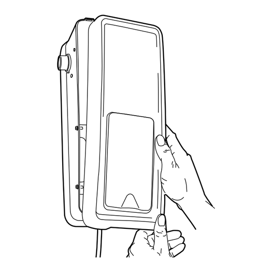
1. Disconnect power.
2. Using a 1/4" socket head or Phillips screwdriver,
remove the two screws located in the bottom of the
operator that are securing the cover (Figure 1).
3. Remove cover (Figure 2).
4. Disconnect wires coming from safety reversing
sensors, door control, door lock and cable tension
monitor.
5. Disconnect 5-wire connector and both of the two wire
(gray/gray and red/black) connectors from logic
board (Figure 3).
6. Using needle nose pliers press and push BBU
connector mounting tabs up and into the panel
one mounting tab at a time (Figure 4).
7. Remove the three screws securing the logic board
bracket to opener.
8. Mount replacement logic board following the previous
steps in inverse order.
9. Position logic board inside opener and secure with
screws. Plug wire connectors into the new logic
board. When reconnecting the wire connectors, be
sure the tabs on the wire connectors are facing
towards the right side of the operator (Figure 5).
10. Replace cover and reconnect power.
11. Refer to the owner's manual for information on
programming instructions for travel limits, setting
forces, and testing the Protector System
the owner's manual for information on the cable
tension monitor and power door lock.
NOTICE: To comply with FCC and or Industry Canada (IC) rules, adjustment or modifications of
this receiver and/or remote control are prohibited, except for changing the code setting or
replacing the battery. THERE ARE NO OTHER USER SERVICEABLE PARTS.
Tested to Comply with FCC Standards FOR HOME OR OFFICE USE. Operation is subject to the
following two conditions: (1) this device may not cause harmful interference, and (2)this device
must accept any interference received, including interference that may cause undesired operation.
Models 041DJ001 and 41DJ001A-390
To prevent possible SERIOUS INJURY or DEATH from
electrocution, disconnect power to opener BEFORE
proceeding.
Figure 1
Figure 3
®
. Refer to
Screws
Figure 4
Figure 5
Logic Board Complete with Plate
5-Wire
Connector
BBU Connector
Connector
2-Wire
Connectors
Tab
Figure 2
2-Wire Connectors
Screw
BBU
Connector
5-Wire
Be sure the
wire connector
tabs are facing
towards the
right side of the
Tab
operator.
Advertisement

Related Manuals for Chamberlain 041DJ001


Summary of Contents for Chamberlain 041DJ001
- Page 1 Models 041DJ001 and 41DJ001A-390 Logic Board Complete with Plate 1. Disconnect power. 2. Using a 1/4" socket head or Phillips screwdriver, remove the two screws located in the bottom of the operator that are securing the cover (Figure 1). To prevent possible SERIOUS INJURY or DEATH from 3.
- Page 2 PROGRAMMING ® NOTICE: If this Security✚ garage door opener is operated with a non-rolling code transmitter, the technical measure in the receiver of the garage door opener, which provides security against code-theft devices, will be circumvented. The owner of the copyright in the garage door opener does not authorize the purchaser or supplier of the non-rolling code transmitter to circumvent that technical measure.
- Page 3 AVERTISSEMENT AVERTISSEMENT AVERTISSEMENT Modèles 41DJ001 et 41DJ001A-390 Carte logique munie de plaque 1. Couper l’alimentation. ATTENTION AVERTISSEMENT AVERTISSEMENT 2. À l’aide d’un tournevis pour vis à pans creux ou d’un tournevis à tête cruciforme de 1/4 po, retirer les deux vis Afin d’éviter toute BLESSURE GRAVE ou la MORT par électrocution, situées au bas de l’actionneur, qui retiennent le couvercle couper l’alimentation de l’ouvre-porte AVANT de continuer.
- Page 4 PROGRAMMATION Si cet ouvre-porte de garage Security ✚ AVIS : ® est utilisé avec une télécommande émettrice à code fixe, le dispositif technique que contient le récepteur de l’ouvre-porte et qui procure une protection contre les vols de code se trouvera contourné. Le détenteur des droits d’auteur de cet ouvre-porte de garage n’autorise pas l’acheteur ni le fournisseur de la télécommande émettrice à...
- Page 5 Modelos 41DJ001 y 41DJ001A-390 Tablero lógico completo con placa 1. Desconecte la energía eléctrica. 2. Con un destornillador con cabeza de cubo o Phillips de 1/4 de pulgada, quite los dos tornillos en la parte inferior del Para evitar posibles LESIONES GRAVES o MUERTE por operador que sujetan la cubierta (Figura 1).
- Page 6 PROGRAMACIÓN AVISO: Si este abrepuertas de garaje Security ✚ ® se hace funcionar con un transmisor de códigos no rodante, se eludirá la medida técnica en el receptor del abrepuertas de garaje que proporciona dispositivos de seguridad contra robo de códigos. El propietario de los derechos de autor sobre el abrepuertas de garaje no autoriza al comprador ni al distribuidor del transmisor de código no rodante a eludir dicha medida técnica.
- Page 8 © 2013, The Chamberlain Group Inc. All Rights Reserved Tous droits réservés 114A3302C Todos los Derechos Reservados...
Need help?
Do you have a question about the 041DJ001 and is the answer not in the manual?
Questions and answers