Advertisement
APPLICATION REQUIREMENTS:
This modification is available to all LA400 North American gate
operators.
FUNCTION:
Allows existing LA400 control board in the field to be replaced or
upgraded with a new LA400 control board.
WARNING
To prevent possible SERIOUS INJURY or DEATH from
electrocution or fire, disconnect power at the fuse box BEFORE
WARNING
proceeding.
REMOVE EXISTING BOARD
1. Remove screws in each corner and open control box cover
(Figure 1).
2. Disconnect terminals leads to both batteries and the 24VAC or
solar input at the board.
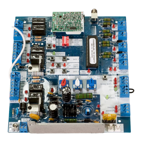
3. Remove the coaxial cable going to the antenna at the board F
connector (Figure 2).
4. Remove all quick connect terminals in use to the logic board
(Figure 2).
• Wiring terminals
• Motor connectors
• Alarms
• Reset terminals
NOTE: Remember location of all wire connections for
reinstallation.
5. Disconnect the earth ground wire from the board
connector (J4).
6. Remove the screws (4) that fasten the control board to the
mounting bracket and remove the existing control board.
I N S T A L L A T I O N I N S T R U C T I O N S
Replacement Kit
K001A6039
Figure 1
Cover
Logic Board
1
Control Board
Screws
Batteries
Mounting
Bracket
Advertisement
Table of Contents

Related Manuals for Chamberlain LiftMaster K001A6039


Summary of Contents for Chamberlain LiftMaster K001A6039
- Page 1 Control Board Replacement Kit K001A6039 APPLICATION REQUIREMENTS: This modification is available to all LA400 North American gate operators. FUNCTION: Allows existing LA400 control board in the field to be replaced or upgraded with a new LA400 control board. I N S T A L L A T I O N I N S T R U C T I O N S WARNING Figure 1 Screws...
-
Page 2: Complete The Installation
F Connector Learn Xmitter Figure 2 S1 DIP Switch R223 CLOSE EDGE Ø14GPØ89ØE ALARM Ø14LGØ89ØE Ø14SKØ89ØE R2Ø7 Z2Ø R227 MAGLOCK OPEN EDGE/ PHOTO R224 SAVE MAGLOCK LEARN SINGLE DUAL MODE XMITTER OPEN EDGE PHOTO 10A 32V PHOTO GATE 1 D1Ø CLOSE DIAGNOSTIC PHOTO... -
Page 3: Program Limits
PROGRAM LIMITS R223 CLOSE 1. Turn Bi-Part switch to desired setting. Set to “Off” for single EDGE Ø14GPØ89ØE ALARM Ø14LGØ89ØE Ø14SKØ89ØE R2Ø7 gate applications. Z2Ø R227 MAGLOCK OPEN EDGE/ PHOTO 2. Press the “LEARN LIMITS” button. R224 SAVE 3. The “SET OPEN LIMIT” LED will blink. MAGLOCK LEARN SINGLE... -
Page 4: Programming Remote
COMPATIBLE REMOTES - 315MHz PROGRAMMING REMOTE 1. Press LEARN XMITTER button (LED will light up). Passport Remote Security✚ ® Remotes 2. Press remote button, the LED will flash, alarm output will CPT13 370LM activate twice. CPT23 371LM 3. Repeat steps 1 and 2 until all remotes are programmed CPT33 372LM (50 remotes maximum). - Page 5 RIGHT AFTER IT STARTS voltage cut-off. life. Replace batteries. NOTE: Replace both batteries at the same time. MOVING (BATTERY RUN) Use only Chamberlain part #K74-30762 for replacement batteries. ➤ 2) A fault has occurred. Check gate for obstructions. GATE OPENS BUT DOES ➤...
-
Page 6: Diagnostic Codes
No Stop Switch Connected Gate 1 Arm Disengaged Gate 2 Arm Disengaged Both Gate Arms Disengaged RPM Reversal Force Reversal Processor Reset ROM Check Failed RAM Check Failed EEPROM Check Failed ©2005, The Chamberlain Group, Inc. 01-32324 All Rights Reserved Printed in Mexico...
Need help?
Do you have a question about the LiftMaster K001A6039 and is the answer not in the manual?
Questions and answers