Table of Contents
Advertisement
Available languages
Available languages
Quick Links
Advertisement
Table of Contents

Related Manuals for FS IPC701-4M-B


Summary of Contents for FS IPC701-4M-B
- Page 1 IPC701-4M-B THERMAL NETWORK BULLET CAMERA WÄRMEBILD-BULLET-NETZWERKKAMERA CAMÉRA RÉSEAU BULLET THERMIQUE サーマルバレッ ト型ネッ トワークカメラ Quick Start Guide V2.0 Quick Start Anleitung Guide de Démarrage Rapide クイックスタートガイド...
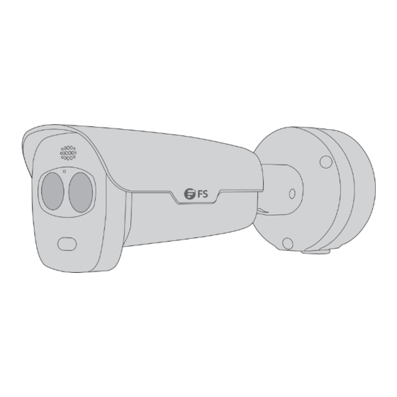
- Page 2 Introduction Thank you for choosing the Thermal Network Bullet Camera. This guide is designed to familiarize you with the structure of the camera and describes how to deploy it in your network. IPC701-4M-B Accessories Hole for Cables Pass Through Drill Diameter( 26mm)
-
Page 3: Hardware Overview
Hardware Overview Ports NO. Ports & Button Description Power Interface Connect to the DC 12V power Ethernet Interface Connect to the Ethernet cable Audio Interface Connect to the external device Alarm Input Interface Input the alarm signal Alarm Output Interface Output the alarm signal RS485 Interface Connect to the external device... -
Page 4: Installation Requirements
Installation Requirements Precautions Make sure the working temperature is maintained at -30°C~60°C, and the relative humidity is ≤95%. Keep the camera from excessive pressure, vibration, moisture, dust, and intensive electromagnetic radiation. Use a power adapter or a PoE device that meets the requirements. Otherwise, the device may be damaged. -
Page 5: Installation
Maintenance If there is dust on the front glass surface, remove the dust gently using an oil-free brush or a dust blowing ball. Clean the glass surface gently from the center outward using the lens cleaning cloth. If necessary, use the cloth dipped with detergent. Installation Inserting the SD Card (Optional) Micro SD Card Slot... -
Page 6: Mounting The Camera
Installing the Waterproof Kit (Optional) Install the supplied waterproof kit to the Ethernet cable/DC cable. NOTE: Please use the self-adhesive waterproof tape (purchased separately) to protect the cable. Mounting the Camera Wall Mounting Concealed Installation Open Installation 1. Drill holes in the wall and knock wall plugs into the holes. - Page 7 Concealed Installation Open Installation 2. Lead the cables out from the outlet as needed. NOTE: For open installation, remove the cover of the outlet 2 and install the cover to the outlet 1 for waterproo ng. 3. Fix the junction box on the wall with the supplied screws.
- Page 8 4. Hang the ring in the junction box on the hook at the bottom of the camera to secure the camera in place (A), and then x the camera onto the junction box with the screws (B). 5. Loosen the screws on the universal joint, adjust the camera to a desired monitoring position, and tighten the screws.
- Page 9 Pole Mounting 1. Fix the junction box onto a pole mount adapter with the screws. NOTE: The pole mount bracket is not included in the accessories. 2. Secure the adapter to a pole by fastening the stainless steel mounting straps. Lead the cables out through the pole.
- Page 10 3. Hang the ring in the junction box on the hook at the bottom of the camera to secure the camera in place, and then x the camera onto the junction box with the screws. NOTE: For open installation, remove the cover of the outlet 2 and install the cover to the outlet 1 for waterproo ng.
- Page 11 4. Loosen the screws on the universal joint, adjust the camera to a desired monitoring positon, and tighten the screws. CAUTION: Do not turn the camera with the universal joint fastened.
-
Page 12: Connecting The Power
Connecting the Power PoE Device Use an Ethernet cable to connect the Ethernet interface of the camera to the PoE port on a PoE device, such as a PoE switch or a PoE NVR. - Page 13 Power Adapter Use the power adapter (purchased separately) to connect the power interface of the camera to the local power source. Log in Camera Before you begin, check that: Your camera is operating properly and connected to the network. The PC you are using is installed with Chrome 45 or later.
- Page 14 1. Open your browser, input the IP address of your camera in the address bar and then press Enter to open the login page. The default IP is 192.168.1.13. 2. Enter the default username and password (admin/admin) and then click Login. IPC701-4M-B English admin...
-
Page 15: Online Resources
Product Warranty FS ensures our customers that for any damage or faulty items due to our workmanship, we will o er a free return within 30 days from the day you receive your goods. This excludes any custom-made items or tailored solutions. - Page 16 Einführung Vielen Dank, dass Sie sich für die Wärmebild-Bullet-Netzwerkkamera entschieden haben. Diese Anleitung soll Sie mit dem Aufbau der Kamera vertraut machen und beschreibt, wie Sie die Kamera in Ihrem Netzwerk einsetzen. IPC701-4M-B Zubehör Schraubenkomponenten x1 Sechskantschlüssel x1 Wasserdichtungskomponenten x1...
- Page 17 Hardware-Übersicht Ports Ports & Tasten Beschreibung Stromversorgungs- Anschließen des 12V Gleichstroms Schnittstelle Ethernet-Schnittstelle Anschließen des Ethernet-Kabels Audio-Schnittstelle Anschließen des externen Geräts Alarmeingang- Alarmeingang Schnittstelle Alarmausgang- Alarmausgang Schnittstelle RS485-Schnittstelle Anschließen des externen Geräts Micro-SD- Setzen Sie die Micro-SD-Karte (seperat erhältlich) ein, um einen Kartensteckplatz lokalen Speicher zu scha en Verwenden Sie einen dünnen Gegenstand und halten Sie die...
- Page 18 Installationsanforderungen Vorsichtsmaßnahmen Stellen Sie sicher, dass eine Betriebstemperatur von -30°C~60°C eingehalten wird und die relative Luftfeuchtigkeit bei ≤95% liegt. Schützen Sie die Kamera vor übermäßigem Druck, Vibrationen, Feuchtigkeit, Staub und hoher elektromagnetischer Strahlung. Verwenden Sie einen Netzteil oder ein PoE-Gerät, das den Anforderungen entspricht. Andernfalls kann das Gerät beschädigt werden.
-
Page 19: Installation
Wenden Sie sich für Informationen zur Wartung an Fachleute. Versuchen Sie nicht, das Gerät selbst zu demontieren. Wir übernehmen keine Verantwortung für Probleme, die durch eine nicht autorisierte Reparatur oder Wartung verursacht werden. Wartung Wenn sich Staub auf der vorderen Glas äche be ndet, entfernen Sie ihn vorsichtig mit einem ölfreien Pinsel oder einem Staubblasball aus Gummi. - Page 20 Entfernen Sie das Gehäuse und die Kartenabdeckung der Kamera, um die Micro-SD-Karte (separat erhältlich) einzusetzen. HINWEIS: Führen Sie kein Hot-Plugging mit der Micro-SD-Karte durch, nachdem sie eingesetzt wurde. Installation der Wasserdichtungskomponenten (optional) Installieren Sie die mitgelieferten Wasserdichtungskomponenten am Ethernet-Kabel/DC-Kabel. HINWEIS: Bitte verwenden Sie selbstklebendes, wasserfestes Klebeband (separat erhältlich), um das Kabel zu sichern.
-
Page 21: Montage Der Kamera
Montage der Kamera Wandmontage Versteckte Montage O ene Montage 1. Bohren Sie Löcher in die Decke und setzen Sie Dübel in die Löcher. Versteckte Montage O ene Montage 2. Führen Sie die Kabel nach Bedarf aus der Ö nung heraus. HINWEIS: Entfernen Sie bei o ener Installation die Abdeckung der Ö... - Page 22 3. Befestigen Sie die Anschlussdose mit den mitgelieferten Schrauben an der Wand. 4. Hängen Sie den Ring in der Anschlussdose an den Haken an der Unterseite der Kamera, um die Kamera zu befestigen (A). Befestigen Sie dann die Kamera mit den Schrauben an der Anschlussdose (B).
- Page 23 5. Lösen Sie die Schrauben am Gelenk, stellen Sie die Kamera auf die gewünschte Position ein und ziehen Sie die Schrauben wieder fest. ACHTUNG: Verändern Sie die Position der Kamera nicht, wenn die Schrauben des Gelenks festgezogen sind. Pfostenmontage...
- Page 24 1. Befestigen Sie die Anschlussdose mit den Schrauben an einem Pfostenmontage-Adapter. HINWEIS: Die Pfostenhalterung ist nicht im Zubehör enthalten. 2. Befestigen Sie den Adapter an einem Pfosten, mithilfe der Befestigungslaschen aus rostfreiem Stahl. Führen Sie die Kabel durch den Pfosten heraus.
- Page 25 3. Hängen Sie den Ring in der Anschlussdose an den Haken an der Unterseite der Kamera, um die Kamera zu befestigen. Befestigen Sie dann die Kamera mit den Schrauben an der Anschlussdose. HINWEIS: Entfernen Sie bei o ener Installation die Abdeckung der Ö nung 2 und bringen Sie die Abdeckung an der Ö...
-
Page 26: Anschließen Der Stromversorgung
Anschließen der Stromversorgung PoE-Gerät Verbinden Sie die Ethernet-Schnittstelle der Kamera über ein Ethernet-Kabel mit dem PoE-Anschluss eines PoE-Geräts, z. B. eines PoE-Switches oder eines PoE-NVR. - Page 27 Netzteil Verwenden Sie das Netzteil (seperat erhältlich), um die Stromschnittstelle der Kamera mit der lokalen Stromquelle zu verbinden. Kamera-Log-In Bevor Sie beginnen, überprüfen Sie, ob: Ihre Kamera einwandfrei funktioniert und mit dem Netzwerk verbunden ist. Auf dem von Ihnen verwendeten PC Chrome 45 oder höher installiert ist.
- Page 28 1. Ö nen Sie Ihren Browser, geben Sie die IP-Adresse Ihrer Kamera in die Adressleiste ein und drücken Sie dann die Eingabetaste, um die Anmeldeseite zu ö nen. Die Standard-IP lautet 192.168.1.13. 2. Geben Sie den standardmäßigen Benutzernamen und das Kennwort (admin/admin) ein und klicken Sie dann auf Login. IPC701-4M-B English Username admin Password...
- Page 29 Kontakt https://www.fs.com/de/contact_us.html Produktgarantie FS garantiert seinen Kunden, dass wir bei Schäden oder fehlerhaften Artikeln, die auf unsere Verarbeitung zurückzuführen sind, eine kostenlose Rückgabe innerhalb von 30 Tagen nach Erhalt der Ware anbieten. Dies gilt nicht für Sonderanfertigungen oder maßgeschneiderte Lösungen.
- Page 30 Introduction Nous vous remercions d'avoir choisi la Caméra Réseau Bullet Thermique. Ce guide a pour but de vous familiariser avec la caméra et décrit comment procéder à son installation. IPC701-4M-B Accessoires Hole for Cables Pass Through Drill Diameter( 26mm) Mounting Hole...
-
Page 31: Aperçu Du Matériel
Aperçu du Matériel Ports N° Ports et Bouton Description Interface d'alimentation Connexion à l'alimentation CC 12V Interface Ethernet Connexion pour le câble Ethernet Interface Audio Connexion à un dispositif externe Interface d'entrée de l'alarme Entrer le signal d’alarme Interface de sortie de l'alarme Émettre le signal d’alarme Interface RS485 Connexion à... -
Page 32: Exigences D'installation
Exigences d'Installation Précautions à Prendre Assurez-vous que la température de fonctionnement est maintenue entre -30 °C et 60 °C, et que l'humidité relative est ≤95 %. Conservez la caméra à l'abri de toute pression excessive, des vibrations, de l'humidité, de la poussière et des rayonnements électromagnétiques intensifs. - Page 33 Maintenance S'il y a de la poussière sur la surface de la lunette frontale, retirez-la délicatement à l'aide d'une brosse non grasse ou d'une boule à poussière. Nettoyez délicatement la surface en verre du centre vers l'extérieur à l'aide du chi on de nettoyage de l'objectif.
-
Page 34: Fixation De La Caméra
Installation des Composants Etanches (En Option) Installez les composants étanches fourni sur le câble Ethernet/le câble DC. NOTE: Veuillez utiliser la bande imperméable auto-adhésive (achetée séparément) pour protéger le câble. Fixation de la Caméra Fixation Murale Installation Cachée Installation Ouverte 1. - Page 35 Installation Ouverte Installation Cachée 2. Acheminez les câbles vers l'extérieur de la prise, selon les besoins. NOTE: Pour une installation ouverte, retirez le couvercle de la prise 2 et installez le couvercle sur la prise 1 pour l'imperméabilisation. 3. Fixez le boîtier de jonction au mur à l'aide des vis fournies.
- Page 36 4. Accrochez l'anneau du boîtier de jonction au crochet situé en bas de la caméra pour xer la caméra en place (A), puis xez la caméra sur le boîtier de raccordement à l'aide des vis (B). 5. Desserrez les vis du joint universel, ajustez la caméra à une position de surveillance souhaitée, puis resserrez les vis.
- Page 37 Fixation sur Poteau 1. Fixez la boîte de jonction sur l'adaptateur de xation pour poteau à l'aide des vis. NOTE : Le support de montage sur poteau n'est pas inclus dans les accessoires. 2. Fixez l'adaptateur à un poteau en attachant les sangles de montage en acier inoxydable. Faites passer les câbles à...
- Page 38 3. Accrochez l'anneau de la boîte de jonction au crochet situé en bas de la caméra pour la stabiliser, puis xez la caméra sur la boîte de jonction à l'aide des vis. NOTE: Pour une installation ouverte, retirez le couvercle de la prise 2 et installez le couvercle sur la prise 1 pour l'imperméabilisation.
- Page 39 4. Desserrez les vis du joint universel, ajustez la caméra à la position de surveillance souhaitée, puis resserrez les vis. ATTENTION : Ne pas faire pivoter la caméra lorsque le joint universel est xé.
-
Page 40: Connexion De L'alimentation
Connexion de l'Alimentation Dispositif PoE Utilisez un câble Ethernet pour connecter l'interface Ethernet de la caméra au port PoE d'un dispositif PoE, tel qu'un commutateur PoE ou un NVR PoE. -
Page 41: Connexion À La Caméra
Adaptateur Electrique Utilisez l'adaptateur d'alimentation (acheté séparément) pour connecter l'interface d'alimentation de l'appareil à la source d'alimentation locale. Connexion à la Caméra Avant de commencer, véri ez que : Votre caméra fonctionne correctement et est connectée au réseau. Le PC que vous utilisez est équipé de Chrome 45 ou d'une version ultérieure. - Page 42 1. Ouvrez un navigateur, saisissez l'adresse IP de votre caméra dans la barre d'adresse, puis appuyez sur Entrée pour ouvrir la page de connexion. L'adresse IP par défaut est 192.168.1.13. 2. Saisissez le nom d'utilisateur et le mot de passe par défaut (admin/admin), puis cliquez sur Login. IPC701-4M-B English Username...
-
Page 43: Garantie Du Produit
Garantie du Produit FS garantit à ses clients que tout article endommagé ou défectueux dû à sa fabrication pourra être retourné gratuitement dans un délai de 30 jours à compter de la date de réception de la marchandise. Ceci exclut les articles fabriqués sur mesure ou les solutions personnalisées. - Page 44 イントロダクション このたびは、 サーマルバレッ ト型ネッ トワークカメラをお買いあげいただき、 誠にありがとうございます。 本ガイドは、 カメラの概要とネッ トワークへの導入方法について説明します。 IPC���-�M-B アクセサリー Hole for Cables Pass Through Drill Diameter( 26mm) Mounting Hole Drill Diameter(4- 6) Direction of the Hole on Side Surface ネジキット x1 六角レンチ x1 防水キット x1 ドリルテンプレートステッカー x1 注: アクセサリーはイラストと異なる場合がありますので、現物をご了承ください。...
- Page 45 ハードウェアの概要 ポート NO. ポート & ボタン 説明 電源インターフェース DC 12V電源に接続する イーサネッ トインターフェース イーサネッ トケーブルに接続する 音声インターフェース 外部機器に接続する アラーム入力インターフェース アラーム信号を入力する アラーム出力インターフ ェース アラーム信号を出力する 外部機器に接続する RS485インターフェース Micro SDカード (別途購入) を挿入し、 ローカルス トレージを Micro SDカードスロッ ト 取得する 15秒間押し続けると、 工場出荷時のデフ ォルト設定に戻る リセッ トボタン (カメラの電源を入れてから10 分以内にのみ有効)。...
- Page 46 設置要件 注意事項 温度が-��℃~��℃に保たれ、 相対湿度が≤ ��%であることを確認して ください。 カメラを過度の圧力、 振動、 ほこり、 腐食性ガス、 強い電磁波から保護して ください。 要件を満たす電源アダプタまたは PoE デバイスを使用して ください。 そうしないと、 デバイスが損傷す る可能性があります。 電源アダプタとカメラ間の電源ケーブルの長さが長すぎないように注意して ください。 長すぎると、 電圧 低下によりカメラが異常動作する可能性があります。 必要に応じて、 電源アダプタと主電源の間のケー ブルを延長して ください。 取り付け中にケーブルを過度に曲げないでください。 ケーブルの接触不良によりカメラが故障する可能 性があります。 重量がかかるためテールケーブルを手で持たないでください。 カメラのケーブルコネクタが緩む可能 性があります。 外部インターフ ェースに接続する場合は、 既存の接続端子を使用し、 ケーブルの端子 (ラッチまたはクラ ンプ) が良好な状態で正し く固定されていることを確認して ください。 ポートとの接触不良や衝撃...
- Page 47 メンテナンス 前面ガラス面にほこりが付着している場合は、 油分を含まないブラシやエアブロアーなどを使用して やさし く クリーニングして ください。 レンズクリーニングクロスでガラスの表面を中心から外側に向かってやさし く クリーニングして くださ い。 また、 必要に応じて洗剤に浸した布を使用して ください。 取り付け SDカードの挿入 (任意) Micro SDカードスロッ ト カメラのスロッ トカバーを取り外し、 Micro SDカード (別売り) を挿入します。 注: Micro SDカードを挿入した後はホットプラグしないでくださ。...
- Page 48 防水キッ トの取り付け (任意) 付属の防水キッ トをイーサネッ トケーブル/DCケーブルに取り付けます。 注: ケーブルを保護するには、粘着防水テープ (別売り) を使用してください。 カメラの取り付け ウォールマウン ト 隠蔽設置 オープン設置 �. 壁に穴を開け、 ウォールプラグを穴に打ち込みます。...
- Page 49 隠蔽設置 オープン設置 �. 必要に応じて、 コンセン トからケーブルを引き出します。 注: オープン設置の場合は、コンセント�のカバーを取り外し、防水用のカバーをコン セント�に取り付けます。 �. ジャンクションボックスを付属のネジで壁に固定します。...
- Page 50 �. ジャンクションボックスのリングをカメラ下部のフ ックに掛けてカメラを所定の位置に固定し (A) 、 ネジでカメラをジャンクションボックスに固定します (B) 。 �. ユニバーサルジョイン トのネジを緩め、 カメラを希望のモニター位置に調整し、 ネジを締めます。 注意: ユニバーサルジョイントを締めたままカメラを回さないでください。...
- Page 51 ポールマウン ト 1. ジャンクションボックスをポールマウン トアダプタにネジで固定します。 注: ポールマウントブラケットは付属品に含まれていません。 �. ステンレススチール製の取り付けス トラップを締めて、 アダプタをポールに固定します。 ケーブルをポ ールに通します。...
- Page 52 �. ジャンクションボックスのリングをカメラ下部のフ ックに掛けてカメラを固定し、 ネジでカメラをジャン クションボックスに固定します。 注: オープン設置の場合は、コンセント�のカバーを外し、防水用のカバーをコンセント �に取り付けます。...
- Page 53 �. ユニバーサルジョイン トのネジを緩め、 カメラを希望のモニター位置に調整し、 ネジを締めます。 注意: ユニバーサルジョイントを締めたままカメラを回さないでください。...
- Page 54 電源の接続 PoEデバイス イーサネッ トケーブルを使用して、 カメラのイーサネッ トインターフェイスをPoEスイッチや PoE NVRな どのPoEデバイスのPoEポートに接続します。...
- Page 55 電源アダプタ 電源アダプタ (別売り) を使用して、 カメラの電源インターフェースをローカル電源に接続します。 カメラへのログイン ログイン前に以下の項目を確認して ください。 カメラが正し く動作し、 ネッ トワークに接続されている。 お使いのPCにChrome 45以降がインストールされている。...
- Page 56 以下の手順に従って、 WEBからカメラへログインして ください。 �. ブラウザを開き、 アドレスバーにカメラのIPアドレスを入力し、 Enterキーを押してログインページを開 きます。 デフ ォルトのIPアドレスは 「���.���.�.��」 です。 �. デフ ォルトのユーザー名 (admin) パスワード (admin) を入力し、 「 Login」 をクリ ックします。 IPC701-4M-B English Username admin ***** Password Forgot Password? Live View Login Reset 注: �. DHCPはデフォルトで有効になっています。ネットワークでDHCPサーバーが使用 されている場合、カメラにIPアドレスが割り当てられることがあります。その場合、割り 当てられたIPアドレスを使用してログインしてください。...
- Page 57 オンラインリソース ダウンロード https://www.fs.com/jp/products_support.html ヘルプセンター https://www.fs.com/jp/service/fs_support.html お問い合わせ https://www.fs.com/jp/contact_us.html 製品保証 FSは、 カスタム製品又はカスタムソリューションを除き、 当社の過失による製品の破損や不良品があっ た場合、 お客様が製品を受け取った日から30日以内に無料で返品、 交換をすることを保証します。 製品保証 : 本製品は、 材料または製造上の欠陥に対して5年間の限定保証を提供します。 保証 の詳細については, 下記のURLをご参照ください。 https://www.fs.com/jp/policies/warranty.html 返品/交換: 返品、 交換を希望される場合、 下記のURLをご参照ください。 https://www.fs.com/jp/policies/day_return_policy.html...
-
Page 58: Compliance Information
(2) this device must accept any interference received, including interference that may cause undesired operation. UKCA Hereby, FS.COM Innovation Ltd declares that this device is in compliance with the Directive SI 2016 No. 1091, SI 2016 No. 1101 and SI 2012 NO. 3032. FS.COM INNOVATION LTD... - Page 59 2014/35/EU, 2011/65/EU und (EU)2015/863 konform ist. Eine Kopie der EU-Konformitätserklärung nden Sie unter www.fs.com/de/company/quality_control.html. FS.COM GmbH déclare par la présente que ce dispositif est conforme à la Directive 2014/30/EU, 2014/35/EU, 2011/65/EU et (EU)2015/863. Une copie de la Déclaration de Conformité de l'UE est disponible à l'adresse suivante https://www.fs.com/fr/company/quality_control.html.
- Page 60 ISED CAN ICES-003(A)/NMB-003(A) English: This device contains licence-exempt transmitter(s)/receiver(s) that comply with Innovation, Science and Economic Development Canada’s licence-exempt RSS(s). Operation is subject to the following two conditions: (1) This device may not cause interference. (2) This device must accept any interference, including interference that may cause undesired operation of the device.
- Page 61 Do not dispose of WEEE as unsorted municipal wasteand have to collect such WEEE separately. Q.C. PASSED Copyright © 2024 FS.COM All Rights Reserved.
Need help?
Do you have a question about the IPC701-4M-B and is the answer not in the manual?
Questions and answers