Table of Contents

Related Manuals for FS TURRET Series


Summary of Contents for FS TURRET Series
- Page 1 TURRET SERIES NETWORK CAMERAS NETZWERKKAMERA DER TURRET-SERIE CAMÉRAS RÉSEAU TURRET タレッ トシリーズネッ トワークカメラ Quick Start Guide V1.0 Quick Start Anleitung Guide de Démarrage Rapide クイックスタートガイド...
- Page 2 Introduction Thank you for choosing the cameras. This guide is designed to familiarize you with the structure of the cameras and describes how to deploy them in your network. IPC501-FC-4M-T/IPC501-FC-8M-T Accessories IPC501-FC-4M-T/IPC501-FC-8M-T Drill Template Hole B: for Mounting Screw Waterproof Kit x1 Screw Kit x1 Drill Template Sticker x1 NOTE:...
-
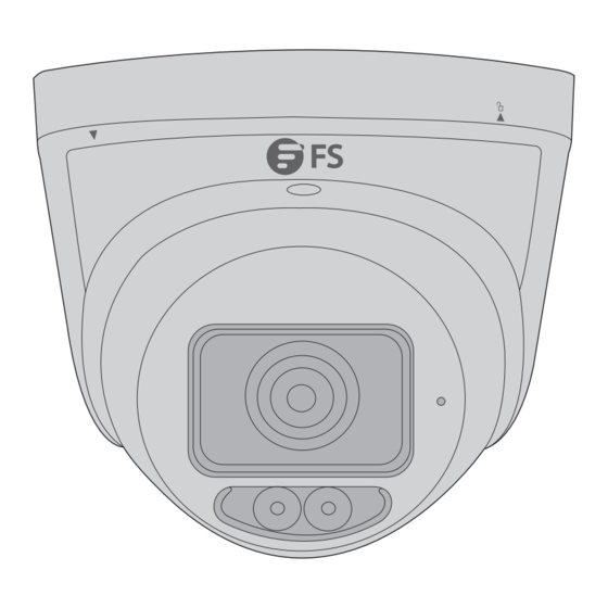
Page 3: Hardware Overview
Hardware Overview IPC501-FC-4M-T/IPC501-FC-8M-T Description Base Plate Housing Warm White Lights Lens Power Interface (12V DC) Ethernet Interface Audio Interface Alarm Interface Micro SD Card Slot Reset Button... -
Page 4: Installation Requirements
NOTE: Use a pin to press and hold the reset button for about 15 seconds to restore factory default settings. Perform this operation within 10 minutes after the device is powered on or the reset will fail otherwise. Installation Requirements Precautions Use a power adapter or a PoE device that meets the requirements. -
Page 5: Installation
Maintenance If there is dust on the front glass surface, remove the dust gently using an oil-free brush or a dust blowing ball. Clean the glass surface gently from the center outward using the lens cleaning cloth. If necessary, use the cloth dipped with detergent. Do not use organic solvents (benzene, alcohol, etc.) to clean the camera. -
Page 6: Mounting The Camera
Installing the Waterproof Kit (Optional) Install the supplied waterproof kit to the Ethernet cable/DC cable. NOTE: Please use the self-adhesive waterproof tape (purchased separately) to protect the cable. Mounting the Camera 1. Attach the sticker to the ceiling, and then drill three guide holes (diameter: 6mm~6.5mm, depth: 30mm) in the marked locations. - Page 7 2. Drill a hole to lead cables out of the ceiling (A) and knock the wall plugs into the guide holes (B). Install mark 3. Loosen the screw and remove the housing from the base plate with the marks aligned.
- Page 8 4. Connect the cable and protect it with waterproof tape, then secure the base plate to the ceiling with the supplied screws.
- Page 9 5. Mount the housing with the marks aligned. 6. Rotate the camera to the desired monitoring direction and then tighten the screw. NOTE: 1. Do not adjust the monitoring direction by force with the screw fully tightened. 2. The above steps are for concealed installation. For open installation, lead the tail cable out of the open slot on the base plate rst and then fasten the screw.
- Page 10 Use an Ethernet cable to connect the Ethernet interface of the camera to the PoE port on a PoE device, such as a PoE switch or a PoE NVR.
-
Page 11: Camera Login
Power Adapter Use the power adapter (purchased separately) to connect the power interface of the camera to the local power source. Camera Login Before you begin, check that: · Your camera is operating properly and connected to the network. · The PC you are using is installed with Chrome 45 or later. Follow these steps to log in to your camera through the Web: 1. - Page 12 IPC501-FC-8M-T Username admin Password Forgot Password? ***** Live View Login Reset NOTE: 1. DHCP is enabled by default. If a DHCP server is used in your network, your camera may be assigned an IP address, and you need to use the assigned IP address to log in.
-
Page 13: Online Resources
Product Warranty FS ensures our customers that for any damage or faulty items due to our workmanship, we will o er a free return within 30 days from the day you receive your goods. This excludes any custom-made items or tailored solutions. - Page 14 Einführung Vielen Dank, dass Sie sich für diese Kamera entschieden haben. Diese Anleitung soll Sie mit dem Aufbau der Kamera vertraut machen und beschreibt, wie Sie sie in Ihrem Netzwerk einsetzen können. IPC501-FC-4M-T/IPC501-FC-8M-T Zubehör IPC501-FC-4M-T/IPC501-FC-8M-T Drill Template Hole B: for Mounting Screw Dichtungssatz x1 Schrauben-Set x1 Aufkleber Bohrschablone x1...
- Page 15 Hardware-Übersicht IPC501-FC-4M-T/IPC501-FC-8M-T Beschreibung Sockelplatte Gehäuse Mikrofon Warmweiße Lichter Objektiv Stromversorgungsschnittstelle (12 V DC) Ethernet-Schnittstelle Audio-Schnittstelle Alarmschnittstelle Micro SD-Kartensteckplatz Reset-Taste...
- Page 16 HINWEIS: Halten Sie die Reset-Taste mit einem Pin etwa 15 Sekunden lang gedrückt, um die Werkseinstellungen wiederherzustellen. Führen Sie diesen Vorgang innerhalb von 10 Minuten nach dem Einschalten des Geräts durch, da der Reset sonst fehlschlägt. Installationsanforderungen Sicherheitsvorkehrungen Verwenden Sie einen Netzadapter oder ein PoE-Gerät, das die Anforderungen der Kamera erfüllt.
- Page 17 Wenden Sie sich für Informationen zur Wartung an Fachpersonal. Versuchen Sie nicht, das Gerät selbst zu demontieren. Wir übernehmen keine Verantwortung für Probleme, die durch nicht autorisierte Reparatur- oder Wartungsarbeiten verursacht werden. Wartung Wenn sich Staub auf der vorderen Glas äche be ndet, entfernen Sie ihn vorsichtig mit einem ölfreien Pinsel oder einem Blasebalg.
- Page 18 ACHTUNG: Die Micro-SD-Karte unterstützt kein Hot-Swapping. Installieren des Dichtungs-Sets (optional) Bringen Sie den mitgelieferten Dichtungssatz am Ethernet-Kabel/DC-Stromkabel an. HINWEIS: Verwenden Sie zum Schutz des Kabels das selbstklebende wasserdichte Band (separat erhältlich).
-
Page 19: Montage Der Kamera
Montage der Kamera 1. Bringen Sie den Aufkleber an der Decke an, und bohren Sie dann drei Führungslöcher (Durchmesser: 6 mm~6,5 mm, Tiefe: 30 mm) an den markierten Stellen. 2. Bohren Sie ein Loch für die Kabelführung aus der Decke (A) und schlagen Sie die Dübel in die Führungslöcher (B). - Page 20 Installationsmarkierung 3. Lösen Sie die Schraube und entfernen Sie das Gehäuse von der Sockelplatte, wobei die Markierungen korrekt ausgerichtet sein müssen. 4. Schließen Sie das Kabel an und bringen Sie das wasserfeste Klebeband an, befestigen Sie dann die Sockelplatte mit den mitgelieferten Schrauben an der Decke.
- Page 21 5. Montieren Sie das Gehäuse mit ausgerichteten Markierungen. 6. Drehen Sie die Kamera in die gewünschte Überwachungsrichtung und ziehen Sie dann die Schraube fest.
- Page 22 HINWEIS: 1. Stellen Sie die Richtung der Kamera nicht bei voll angezogener Schraube mit Gewalt ein. 2. Die obigen Schritte gelten für den verdeckten Einbau. Bei o ener Installation führen Sie das Endkabel zuerst aus dem o enen Schlitz der Sockelplatte heraus und ziehen dann die Schraube an.
- Page 23 Netzadapter Verwenden Sie den (separat erhältlichen) Netzadapter, um die Stromschnittstelle der Kamera mit der lokalen Stromquelle zu verbinden. Anmeldung der Kamera Bevor Sie beginnen, überprüfen Sie, ob: · Ihre Kamera ordnungsgemäß funktioniert und mit dem Netzwerk verbunden ist. · der von Ihnen verwendete PC verfügt über Chrome 45 oder höher. Führen Sie die folgenden Schritte aus, um sich über das Internet bei Ihrer Kamera anzumelden: 1.
- Page 24 2. Geben Sie den Standard-Benutzernamen und das Standard-Passwort (admin/admin) ein, und klicken Sie dann auf Login. IPC501-FC-8M-T Username admin Password Forgot Password? ***** Live View Login Reset HINWEIS: 1. DHCP ist standardmäßig aktiviert. Wenn in Ihrem Netzwerk ein DHCP-Server verwendet wird, wird Ihrer Kamera möglicherweise eine IP-Adresse zugewiesen und Sie müssen die zugewiesene IP-Adresse verwenden, um sich anzumelden.
- Page 25 Kontakt https://www.fs.com/de/contact_us.html Produktgarantie FS garantiert seinen Kunden, dass wir bei Schäden oder fehlerhaften Artikeln, die auf unsere Verarbeitung zurückzuführen sind, eine kostenlose Rückgabe innerhalb von 30 Tagen nach Erhalt der Ware anbieten. Dies gilt nicht für Sonderanfertigungen oder maßgeschneiderte Lösungen.
- Page 26 Introduction Nous vous remercions d'avoir choisi la Caméra Réseau Turret. Ce guide est conçu pour vous familiariser avec la caméra et décrit comment procéder à son déploiement. IPC501-FC-4M-T/IPC501-FC-8M-T Accessoires IPC501-FC-4M-T/IPC501-FC-8M-T Drill Template Hole B: for Mounting Screw Kit d'Étanchéité x1 Kit de Vis x1 Autocollant de Schéma de Perçage x1 NOTE :...
-
Page 27: Présentation Du Matériel
Présentation du Matériel IPC501-FC-4M-T/IPC501-FC-8M-T N° Description Plaque de Base Boîtier Microphone Lumières Banches Chaudes Objectif Interface d'Alimentation (12V DC) Interface Ethernet Interface Audio Interface d'Alarme Fente pour Carte Micro SD Bouton de Réinitialisation... -
Page 28: Conditions D'installation
NOTE : Utilisez une tige pour appuyer sur le bouton de réinitialisation pendant environ 15 secondes a n de rétablir les paramètres d'usine par défaut. E ectuez cette opération dans les 10 minutes qui suivent la mise sous tension de l'appareil, sinon la réinitialisation échouera. -
Page 29: Installation De La Caméra
Contactez des professionnels pour obtenir des informations sur la maintenance. N'essayez pas de démonter la caméra par vous-même. Nous n'assumons aucune responsabilité pour les problèmes causés par une réparation ou un entretien non autorisé. Maintenance S'il y a de la poussière sur la surface vitrée frontale, enlevez-la délicatement à l'aide d'une brosse sans huile ou d'une boule de dépoussiérage. - Page 30 ATTENTION : Ne pas brancher la carte Micro SD à chaud une fois insérée. Installation du Kit d'Étanchéité (En Option) Installez le kit d'étanchéité fourni sur le câble Ethernet/câble CC. REMARQUE : Utilisez la bande étanche autocollante (achetée séparément) pour protéger le câble.
- Page 31 Installation de la Caméra 1. Placez l'autocollant au plafond, puis percez trois ori ces de guidage (diamètre : 6mm~6.5mm, profondeur : 30mm) aux endroits marqués.
- Page 32 2. Percez un ori ce pour acheminer le câble hors du plafond (A) et enfoncez les chevilles dans les ori ces de guidage (B). Marque de Positionnement 3. Desserrez la vis et retirer le boîtier de la plaque de base en alignant les marques. 4.
- Page 33 5. Installez le boîtier en alignant les marques. 6. Faites pivoter la caméra dans le sens de surveillance souhaité, puis serrez la vis.
- Page 34 REMARQUE : 1. Ne pas régler la direction de surveillance en forçant lorsque la vis est complètement serrée. 2. Les étapes ci-dessus concernent l'installation dissimulée. Pour une installation ouverte, faites d'abord sortir le câble d'alimentation de la fente ouverte sur la plaque de base, puis xez la vis.
-
Page 35: Connexion À La Caméra
Adaptateur d'Alimentation Utilisez l'adaptateur d'alimentation (acheté séparément) pour connecter l'interface d'alimentation de la caméra à la source d'alimentation locale. Connexion à la Caméra Avant de commencer, véri ez que · Votre caméra fonctionne correctement et qu'elle est connectée au réseau. ·... - Page 36 IPC501-FC-8M-T Username admin Password Forgot Password? ***** Live View Login Reset NOTE : 1. Le protocole DHCP est activé par défaut. Si un serveur DHCP est utilisé dans votre réseau, une adresse IP peut être attribuée à votre appareil photo et vous devez utiliser l'adresse IP attribuée pour vous connecter.
-
Page 37: Garantie Du Produit
Garantie du Produit FS garantit à ses clients que tout article endommagé ou défectueux en raison de sa fabrication pourra être retourné gratuitement dans un délai de 30 jours à compter de la date de réception de la marchandise. Cette garantie ne s'applique pas aux articles fabriqués sur mesure ou aux solutions personnalisées. - Page 38 イントロダクション このたびは、FSカメラをお買いあげいただき、誠にありがとうございます。本ガイドは、カメラ の構造とネットワークへの導入方法について説明します。 IPC501-FC-4M-T/IPC501-FC-8M-T アクセサリー IPC���-FC-�M-T/IPC���-FC-�M-T Drill Template Hole B: for Mounting Screw 防水キット x1 ネジキット x1 ドリル用テンプレート・ステッカー x1 注:アクセサリー類はイラストと異なる場合があります。...
- Page 39 ハードウェアの概要 IPC���-FC-�M-T/IPC���-FC-�M-T 番号 説明 ベースプレート ハウジング マイク ウォームホワイトライト レンズ 電源インタフェース(��V DC) イーサネットインタフェース 音声インタフェース アラームインタフェース マイクロSDカードスロット リセットボタン...
- Page 40 注:工場出荷時のデフォルト設定に戻すには、ピンを使用してリセットボタンを約��秒 間押し続けます。この操作は、デバイスの電源が入ってから��分以内に実行してください。 そうしないと、リセットが失敗します 設置要件 注意事項 要件を満たす電源アダプターまたはPoEデバイスを使用して ください。 そうしないと、 デバイスが破損す る可能性があります。 電源アダプタとカメラの間の電源ケーブルの長さが長すぎないことを確認して ください。 必要であれ ば、 電源アダプタと主電源間のケーブルを長く して ください。 ケーブルを曲げすぎると、 接触不良による故障の恐れがあります。 テールケーブルを手で持って加重をかけないでください。 カメラのケーブルコネクタが緩む恐れがあり ます。 外部インタフェースに接続する場合は、 既存の接続端子を使用し、 ケーブル端子(ラッチまたはクランプ) が良好な状態で適切に固定されていることを確認して ください。 ポートとの接触不良や、 衝撃や揺れによるケーブルの緩みを防ぐため、 取り付け時にケーブルが緊張し ないよう、 適度な余裕を持たせて ください。 取り付けが完了するまで、 デバイスの保護フィ ルムは剥がさないでください。 装置の電源を入れる前に 取り外して ください。 壁や天井がカメラの重量を支えるのに十分な強度があることを確認して ください。 メンテナンスについては専門家にお問い合わせください。...
- Page 41 メンテナンス フロン トガラス面にホコリが付着している場合は、 油分を含まないブラシやエアブロアーなどを使用 してやさし く クリーニングして ください。 レンズクリーニングクロスを使用して、 ガラスの表面を中心から外側に向かってやさし く クリーニング して ください。 必要に応じて、 洗剤に浸した布を使用して ください。 カメラのクリーニングには有機溶剤(ベンジン、 アルコールなど)を使用しないでください。 設置 SDカードの挿入 (オプション) カメラのハウジングを取り外し、 マイクロSDカード(別売り)を挿入します。 注意:マイクロSDカードを挿入した後はホットプラグしないでください。...
- Page 42 防水キッ ト (オプション) の取り付け 付属の防水キットをイーサネットケーブル/DCケーブルに取り付けます。 注:ケーブルの保護には粘着防水テープ(別売り)をご使用ください。 カメラの取り付け �. ステッカーを天井に貼り、印をつけた位置にガイド穴(直径�mm~�.�mm、深さ��mm)を�つ開 けます。...
- Page 43 �. 天井からケーブルを出すための穴(A)を開け、壁のプラグをガイド穴(B)に打ち込みます。 インストールマーク �. ネジを緩め、マークを合わせてベースプレートからハウジングを取り外します。...
- Page 44 �. ケーブルを接続し、防水テープで保護した後、付属のネジでベースプレートを天井に固定します。...
- Page 45 �. マークを合わせてハウジングを取り付けます。 �. カメラを希望の監視方向に回転させ、ネジを締めます。 注:�. ネジを締めきった状態で、無理にモニターの向きを調整しないでください。 �. 上記の手順は隠蔽設置の場合です。オープン設置の場合は、まずベースプレートのオー プンスロットからテールケーブルを引き出し、ネジを締めてください。...
- Page 46 イーサネットケーブルを使用して、カメラのイーサネットインターフェイスをPoEスイッチやPoE NVRなどのPoEデバイスのPoEポートに接続します。...
- Page 47 電源アダプタ 電源アダプタ(別売り)を使用して、カメラの電源インターフェイスをローカル電源に接続しま す。 カメラのログイン 始める前に、 以下のことを確認して ください。 · カメラは正常に動作し、 ネッ トワークに接続されています。 · ご使用のPCにはChrome ��以降がインス トールされています。 以下の手順に従って、 ウェブからカメラにログインして ください。 �. ブラウザを開き、 アドレスバーにカメラのIPアドレスを入力し、 Enterキーを押してログインページを開き ます。 デフ ォルトのIPアドレスは���.���.�.��です。 �. デフ ォルトのユーザー名とパスワード(admin/admin)を入力し、 「 Login」 をクリ ックします。...
- Page 48 IPC501-FC-8M-T Username admin Password Forgot Password? ***** Live View Login Reset 注:�. DHCPはデフォルトで有効になっています。ネットワークでDHCPサーバが使用さ れている場合、カメラにIPアドレスが割り当てられ、ログインするには割り当てられたIP アドレスを使用する必要があります。 �. 初回ログイン時にプラグインのインストールが必要な場合があります。画面の指示に従 ってインストールを完了し、再度ブラウザを開いてログインしてください。 �. デフォルトのパスワードは、初回ログイン時のみのものです。セキュリティを確保する ため、初回ログイン後にパスワードを変更してください。数字、文字、特殊文字の�つの 要素をすべて含む、少なくとも�文字の強力なパスワードを設定することをお勧めします。 �. パスワードが変更されている場合は、新しいパスワードでログインしてください。...
- Page 49 オンラインリソース ダウンロード https://www.fs.com/jp/products_support.html ヘルプセンター https://www.fs.com/jp/service/fs_support.html お問い合わせ https://www.fs.com/jp/contact_us.html 製品保証 FSは、当社の管理による破損や不良品があった場合、お客様のお手元に商品が届いてから��日以 内であれば、特注品やオーダーメイドを除き、無料で返品及び交換を承ります。 保証:この製品は、材料または製造上の欠陥に対して�年間の限定保証を提供いたします。 保証の詳細については、下記をご参照ください。 https://www.fs.com/jp/policies/warranty.html 返品 ・ 交換 : 返品及び交換を希望される場合、 方法については下記をご参照ください。 https://www.fs.com/jp/policies/day_return_policy.html...
-
Page 50: Compliance Information
(2) this device must accept any interference received, including interference that may cause undesired operation. UKCA Hereby, FS.COM Innovation Ltd declares that this device is in compliance with the Directive SI 2016 No. 1091, SI 2016 No. 1101 and SI 2012 NO. 3032. FS.COM INNOVATION LTD... - Page 51 2014/35/EU, 2011/65/EU und (EU)2015/863 konform ist. Eine Kopie der EU-Konformitätserklärung nden Sie unter www.fs.com/de/company/quality_control.html. FS.COM GmbH déclare par la présente que ce dispositif est conforme à la Directive 2014/30/EU, 2014/35/EU, 2011/65/EU et (EU)2015/863. Une copie de la Déclaration de Conformité de l'UE est disponible à l'adresse suivante https://www.fs.com/fr/company/quality_control.html.
- Page 52 ISED CAN ICES-003(A)/NMB-003(A) English: This device contains licence-exempt transmitter(s)/receiver(s) that comply with Innovation, Science and Economic Development Canada’s licence-exempt RSS(s). Operation is subject to the following two conditions: (1) This device may not cause interference. (2) This device must accept any interference, including interference that may cause undesired operation of the device.
- Page 53 Do not dispose of WEEE as unsorted municipal wasteand have to collect such WEEE separately. Q.C. PASSED Copyright © 2023 FS.COM All Rights Reserved.
Need help?
Do you have a question about the TURRET Series and is the answer not in the manual?
Questions and answers