Table of Contents

Subscribe to Our Youtube Channel
Related Manuals for FS BULLET Series


Summary of Contents for FS BULLET Series
- Page 1 BULLET SERIES NETWORK CAMERAS NETZWERKKAMERA DER BULLET-SERIE CAMÉRA RÉSEAU DE LA GAMME BULLET バレッ トシリーズネッ トワークカメラ Quick Start Guide V1.0 Quick Start Anleitung Guide de Démarrage Rapide クイックスタートガイド...
- Page 2 Introduction Thank you for choosing the cameras. This guide is designed to familiarize you with the structure of the cameras and describes how to deploy them in your network. IPC305-5M-B/IPC304-8M-B Accessories Waterproof Kit x1 Screw Kit x1 Drill Template Sticker x1 Wrench x1 NOTE: The accessories may vary from illustration, please prevail in kind.
-
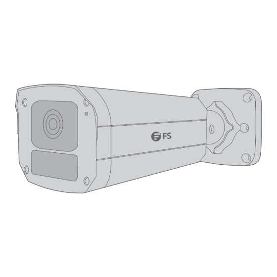
Page 3: Hardware Overview
Hardware Overview IPC305-5M-B/IPC304-8M-B Name Description Power Interface Connect to the DC 12V power Ethernet Interface Connect to an Ethernet cable Audio Interface Input/output the audio signal Alarm Interface Input/output the alarm signal Insert the Micro SD card (purchased separately) Micro SD Card Slot to get a local storage Installation Requirements Precautions... -
Page 4: Maintenance
Take proper waterproof measures by requirements before using the device outdoors. Make sure the device is securely installed or placed on a at surface to prevent falling. Do not remove the protective lm until mounting is nished and remove it before powering. Unless otherwise speci ed, do not stack devices. -
Page 5: Installation
Installation Inserting the Micro SD Card (Optional) Open the bottom cover to insert the Micro SD card (purchased separately) into the camera. CAUTION: Do not hot plug the Micro SD card after it is inserted. Installing Waterproof Connector (Optional) -
Page 6: Mounting The Camera
Install the supplied waterproof kit to the Ethernet cable/DC cable. NOTE: Please use self-adhesive waterproof tape (purchased separately) to protect the cable. Mounting the Camera 1. Locate the positions of the guide holes based on the drill template sticker. Drill holes in the wall. Knock the wall plugs into the holes and tighten the plugs. - Page 7 2. Loosen the locknut and adjust the angle of the monitor for convenient installation. 3. Connect the cables and secure the camera on the wall with the supplied screws. 4. Adjust the opening of the universal joint to get the desired monitoring direction, and tighten the locknut.
-
Page 8: Connecting The Power
Connecting the Power PoE Device Use an Ethernet cable to connect the Ethernet interface of the camera to the PoE port on a PoE device, such as a PoE switch or a PoE NVR. -
Page 9: Power Adapter
Power Adapter Use the power adapter (purchased separately) to connect the power interface of the camera to the local power source. Camera Login Before you begin, check that: Your camera is operating properly and connected to the network. The PC you are using is installed with Chrome 45 or later. Follow these steps to log in to your camera through the Web: 1. - Page 10 IPC305-5M-B Username admin Password Forgot Password? ***** Live View Login Reset NOTE: 1. DHCP is enabled by default. If a DHCP server is used in your network, your camera may be assigned an IP address, and you need to use the assigned IP address to log in.
-
Page 11: Online Resources
Product Warranty FS ensures our customers that for any damage or faulty items due to our workmanship, we will o er a free return within 30 days from the day you receive your goods. This excludes any custom-made items or tailored solutions. - Page 12 Einführung Vielen Dank, dass Sie sich für diese Kamera entschieden haben. Diese Anleitung soll Sie mit dem Aufbau der Kamera vertraut machen und beschreibt, wie Sie sie in Ihrem Netzwerk einsetzen können. IPC305-5M-B/IPC304-8M-B Zubehör Dichtungssatz x1 Schrauben-Set x1 Aufkleber Bohrschablone x1 Stern-Schlüssel x1 HINWEIS: Das Zubehör kann von der Abbildung abweichen, bitte haben Sie Verständnis...
- Page 13 Hardware-Übersicht IPC305-5M-B/IPC304-8M-B Name Beschreibung Strom-Schnittstelle Anschluss an den DC-Strom mit 12 V Ethernet-Schnittstelle Anschluss des Ethernet-Kabels Audio-Schnittstelle Eingang/Ausgang des Audiosignals Alarm-Schnittstelle Eingang/Ausgang des Alarmsignals Legen Sie die Micro-SD-Karte (separat erhältlich) Micro SD-Kartensteckplatz ein, um einen lokalen Speicher zu scha en. Installationsanforderungen Sicherheitshinweise Die Installation, Demontage und Wartung des Geräts und seines Zubehörs müssen von...
-
Page 14: Wartung
Stellen Sie sicher, dass das Gerät fest installiert ist oder auf einer ebenen Fläche steht, damit es nicht herunterfällt. Entfernen Sie die Schutzfolie erst nach Abschluss der Montage und vor dem Einschalten. Sofern nicht anders angegeben, dürfen Sie die Geräte nicht stapeln. Stellen Sie sicher, dass die Stromversorgung eine stabile Spannung liefert und der Netzadapter oder das PoE-Gerät den Anforderungen entspricht. - Page 15 Installation Einlegen der SD-Karte (optional) Ö nen Sie die untere Abdeckung, um die Micro-SD-Karte (separat erhältlich) in die Kamera einzulegen. ACHTUNG: Die Micro-SD-Karte unterstützt kein Hot-Swapping. Installieren des Dichtungssatzes (optional)
-
Page 16: Montage Der Kamera
Bringen Sie das mitgelieferte wasserdichte Kit am Ethernetkabel/DC-Kabel an. HINWEIS: Verwenden Sie zum Schutz des Kabels das selbstklebende wasserdichte Band (separat erhältlich). Montage der Kamera 1. Ermitteln Sie die Positionen der Führungslöcher anhand der Bohrschablone. Bohren Sie Löcher in die Wand. Schlagen Sie die Dübel in die Löcher und ziehen Sie die Dübel fest. HINWEIS: Die Deckenmontage ist ähnlich wie die Wandmontage. - Page 17 2. Lösen Sie die Kontermutter und stellen Sie den Winkel des Monitors für eine bequeme Installation ein. 3. Schließen Sie die Kabel an und befestigen Sie die Kamera mit den mitgelieferten Schrauben an der Wand. 4. Stellen Sie die Ö nung des Gelenks ein, um die gewünschte Richtung der Kamera einzustellen und ziehen Sie die Kontermutter fest.
-
Page 18: Anschließen Der Stromversorgung
Anschließen der Stromversorgung PoE-Gerät Verbinden Sie die Ethernet-Schnittstelle der Kamera über ein Ethernet-Kabel mit dem PoE-Port eines PoE-Geräts, z. B. eines PoE-Switches oder eines PoE-NVR. - Page 19 Netzadapter Verwenden Sie den (separat erhältlichen) Netzadapter, um die Stromschnittstelle der Kamera mit der lokalen Stromquelle zu verbinden. Anmeldung der Kamera Bevor Sie beginnen, überprüfen Sie, ob: Ihre Kamera ordnungsgemäß funktioniert und mit dem Netzwerk verbunden ist. der von Ihnen verwendete PC verfügt über Chrome 45 oder höher. Führen Sie die folgenden Schritte aus, um sich über das Internet bei Ihrer Kamera anzumelden: 1.
- Page 20 IPC305-5M-B Username admin Password Forgot Password? ***** Live View Login Reset HINWEIS: 1. DHCP ist standardmäßig aktiviert. Wenn in Ihrem Netzwerk ein DHCP-Server verwendet wird, wird Ihrer Kamera möglicherweise eine IP-Adresse zugewiesen und Sie müssen die zugewiesene IP-Adresse verwenden, um sich anzumelden.
- Page 21 Kontakt https://www.fs.com/de/contact_us.html Produktgarantie FS garantiert seinen Kunden, dass wir bei Schäden oder fehlerhaften Artikeln, die auf unsere Verarbeitung zurückzuführen sind, eine kostenlose Rückgabe innerhalb von 30 Tagen nach Erhalt der Ware anbieten. Dies gilt nicht für Sonderanfertigungen oder maßgeschneiderte Lösungen.
- Page 22 Introduction Nous vous remercions d'avoir choisi la Caméra Réseau Bullet. Ce guide a pour but de vous familiariser avec la caméra et décrit comment procéder à son installation. IPC305-5M-B/IPC304-8M-B Accessoires Kit d'Étanchéité x 1 Kit de Vis x 1 Autocollant de Schéma de Perçage x 1 Clé...
-
Page 23: Présentation Du Matériel
Présentation du Matériel IPC305-5M-B/IPC304-8M-B Dénomination Description Interface d'Alimentation Connexion à l'alimentation 12V DC Interface Ethernet Connexion pour câble Ethernet Interface Audio Entrée/sortie du signal audio Interface d'Alarme Entrée/sortie du signal d'alarme Insérer la carte Micro SD (achetée séparément) pour Fente pour Carte Micro SD disposer d'un espace de stockage local Conditions d'Installation Précautions... - Page 24 Avant d'utiliser l'appareil dans un environnement extérieur, prenez les mesures d'étanchéité adéquates en fonction des exigences. Veillez à ce que l'appareil soit solidement installé ou placé sur une surface plane pour éviter qu'il ne tombe. Ne pas retirer le lm protecteur avant d'avoir terminé l'installation et retirez-le avant de mettre l'appareil sous tension.
- Page 25 Installation Insertion de la Carte Micro SD (en Option) Ouvrez le couvercle inférieur pour insérer la carte Micro SD (achetée séparément). ATTENTION : Ne pas insérer la carte Micro SD à chaud après sa mise en place. Installation du kit d'Étanchéité (en Option)
-
Page 26: Installation De La Caméra
Installez le kit d'étanchéité fourni sur le câble Ethernet/câble DC. NOTE : Utilisez du ruban adhésif étanche (acheté séparément) pour protéger le câble. Installation de la Caméra 1. Déterminez la position des trous de xation en utilisant l'autocollant du schéma de perçage. Percez les trous dans le mur. - Page 27 2. Desserrez le contre-écrou et réglez l'angle de vision pour une installation optimale. 3. Branchez les câbles et xez la caméra au mur à l'aide des vis fournies. 4. Réglez l'ouverture du bras articulé pour obtenir la direction de surveillance souhaitée, et serrez le contre-écrou.
-
Page 28: Connexion De L'alimentation
Connexion de l'Alimentation Dispositif PoE Utilisez un câble Ethernet pour connecter l'interface Ethernet de la caméra au port PoE d'un périphérique PoE, tel qu'un switch PoE ou un NVR PoE. -
Page 29: Adaptateur D'alimentation
Adaptateur d'Alimentation Utilisez l'adaptateur d'alimentation (acheté séparément) pour connecter l'interface d'alimentation de la caméra à la source d'alimentation locale. Connexion à la Caméra Avant de commencer, véri ez que Votre caméra fonctionne correctement et est connectée au réseau. Le PC que vous utilisez est équipé de Chrome 45 ou d'une version ultérieure. Procédez aux étapes suivantes pour vous connecter à... - Page 30 IPC305-5M-B Username admin Password Forgot Password? ***** Live View Login Reset NOTE: 1. Le protocole DHCP est activé par défaut. Si un serveur DHCP est utilisé dans votre réseau, une adresse IP peut être attribuée à la caméra et vous devez utiliser l'adresse IP attribuée pour vous connecter.
-
Page 31: Garantie Du Produit
Garantie du Produit FS garantit à ses clients que tout article endommagé ou défectueux en raison de sa fabrication pourra être retourné gratuitement dans un délai de 30 jours à compter de la date de réception de la marchandise. Cette garantie ne s'applique pas aux articles fabriqués sur mesure ou aux solutions personnalisées. - Page 32 イントロダクション この度はカメラをお買い上げいただき、ありがとうございます。このガイドでは、カメラの構造と ネットワークへの導入方法について説明します。 IPC305-5M-B/IPC304-8M-B アクセサリー 防水キット x� ネジキット x� ドリルテンプレートステッカー x� レンチ x� 注:付属品はイラストと異なる場合がありますので、ご了承ください。...
- Page 33 ハードウェア概要 IPC305-5M-B/IPC304-8M-B 番号 名称 説明 � 電源インタフェース DC ��V電源に接続 � イーサネットインタフェース イーサネットケーブルに接続する � オーディオインターフェース オーディオ信号を入出力する � アラームインターフェース アラーム信号を入出力する マイクロSDカード(別途購入)を挿入し、ロ � マイクロSDカードスロット ーカルストレージを取得する インストール要件 注意事項 デバイスおよび付属品の取り付け、 取り外し、 メンテナンスは、 資格のある担当者が行う必要がありま す。 デバイスは、 温度、 湿度、 ほこり、 腐食性ガス、 電磁放射、 換気などの条件を満たす適切な環境で保管 または使用して ください。...
- Page 34 屋外で使用する場合は、 要件に応じた適切な防水対策を講じて ください。 落下を防ぐため、 デバイスがしっかりと設置されているか、 平らな場所に置かれていることを確認して く ださい。 取り付けが完了するまで保護フィ ルムを剥がさず、 電源を入れる前に剥がして ください。 特に指定がない限り、 デバイスを積み重ねないでください。 安定した電圧を提供する電源、 および電源アダプタまたはPoEデバイスが要件を満たしていることを確 認して ください。 出力電力が接続されているすべてのデバイスの合計最大電力を超えていることを確認 して ください。 電源アダプタとカメラの間の電源ケーブルが長すぎないことを確認して ください。 必要であれば、 電源 アダプター と主電源間のケーブルを長く して ください。 取り付けの際、 ケーブルを曲げ過ぎないでください。 外部インターフェースに接続する場合は、 既存の接続端子を適切に固定して ください。 取り付けの際、 ケーブルが引っ張られないよう、 適切なマージンを確保して ください。 デバイスの使用には、 顔、 指紋、 ナンバープレート、 電子メール、 電話番号、 GPSなどの個人情報の収集 が含まれる場合があります。...
- Page 35 取り付け マイクロSDカードの挿入(オプション) 底部カバーを開け、マイクロSDカード(別売)をカメラに挿入します。 注意 : Micro SDカードを挿入した後、ホットプラグで接続しないでください。 防水キッ トの取り付け(オプション)
- Page 36 付属の防水キットをイーサネットケーブル/DCケーブルに取り付けます。 注:ケーブルを保護するために自己粘着性防水テープ(別売)をご使用ください。 カメラの取り付け �. ドリルテンプレートシールをもとに、ガイド穴の位置を決めます。壁に穴を開けます。壁のプラ グを穴に差し込み、プラグを締めます。 注:天井取り付けは壁取り付けと似ています。部品は後者を例にしています。 ロックナッ ト...
- Page 37 �. ロックナットを緩めてモニターの角度を調整し、設置しやすくします。 �. ケーブルを接続し、付属のネジでカメラを壁に固定します。 �. ユニバーサルジョイントの開度を調節し、希望の監視方向になるようにし、ロックナットを締め 付けます。...
- Page 38 電源の接続 PoEデバイス イーサネットケーブルを使用して、カメラのイーサネットインタフェースをPoEスイッチやPoE NVRなどのPoEデバイスのPoEポートに接続します。...
- Page 39 電源アダプタ 電源アダプタ(別売)を使用して、カメラの電源インタフェースをローカル電源に接続します。 カメラのログイン 作業を始める前に、次のことを確認してください。 カメラが正しく動作し、ネットワークに接続されていること。 お使いのPCにChrome ��以降がインストールされていること。 以下の手順に従って、ウェブからカメラにログインしてください。 �. ブラウザを開き、アドレスバーにカメラのIPアドレスを入力し、Enterを押してログインページ を開きます。デフォルトのIPは���.���.�.��です。 �. デフォルトのユーザー名とパスワード(admin/admin)を入力し、Loginをクリックします。...
- Page 40 IPC305-5M-B Username admin Password Forgot Password? ***** Live View Login Reset 注:�. DHCPはデフォルトで有効になっています。ネットワークでDHCPサーバが使 用されている場合、カメラにIPアドレスが割り当てられ、ログインするには割り当て られたIPアドレスを使用する必要があります。 �. 初回ログイン時にプラグインのインストールが必要な場合があります。画面の指示 に従ってインストールを完了し、再度ブラウザを開いてログインしてください。 �. デフォルトのパスワードは、初回ログイン時のみのものです。セキュリティを確 保するため、初回ログイン後にパスワードを変更してください。数字、文字、特殊文 字の�つの要素をすべて含む、少なくとも�文字の強力なパスワードを設定することを 強くお勧めします。 �. パスワードが変更された場合は、新しいパスワードでログインしてください。...
- Page 41 オンラインリソース ダウンロード https://www.fs.com/jp/products_support.html ヘルプセンター https://www.fs.com/jp/service/fs_support.htm お問い合わせ https://www.fs.com/jp/contact_us.html 製品保証 FSでは、弊社の製造技術による破損や不良品については、商品をお受け取りになった日から��日 以内であれば、無料で返品を承ります。ただし、これにはカスタム製品やオーダーメイドは含まれ ません。 保証:この製品は、材料または製造上の欠陥に対して�年間の限定保証を提供します。保 証の詳細については、次のサイトでご確認ください: https://www.fs.com/jp/policies/warranty.html 返品:返品したい場合は、返品方法に関する情報が次のサイトにご覧ください: https://www.fs.com/jp/policies/day_return_policy.html...
-
Page 42: Compliance Information
(2) this device must accept any interference received,including interference that may cause undesired operation. UKCA Hereby, FS.COM Innovation Ltd declares that this device is in compliance with the Directive SI 2016 No. 1091, SI 2016 No. 1101 and SI 2012 NO. 3032. FS.COM INNOVATION LTD... - Page 43 2014/35/EU, 2011/65/EU und (EU)2015/863 konform ist. Eine Kopie der EU-Konformitätserklärung nden Sie unter www.fs.com/de/company/quality_control.html. FS.COM GmbH déclare par la présente que ce dispositif est conforme à la Directive 2014/30/EU, 2014/35/EU, 2011/65/EU et (EU)2015/863. Une copie de la Déclaration de Conformité de l'UE est disponible à l'adresse suivante https://www.fs.com/fr/company/quality_control.html.
-
Page 44: Waste Electrical And Electronic Equipment (Weee)
Do not dispose of WEEE as unsorted municipal wasteand have to collect such WEEE separately. Q.C. PASSED Copyright © 2023 FS.COM All Rights Reserved.
Need help?
Do you have a question about the BULLET Series and is the answer not in the manual?
Questions and answers