
Subscribe to Our Youtube Channel
Related Manuals for FS IPC Series


Summary of Contents for FS IPC Series
- Page 1 IPC SERIES PTZ CAMERAS PTZ KAMERAS DER SERIE IPC CAMÉRAS PTZ DE LA SÉRIE IPC IPCシリーズPTZカメラ Quick Start Guide V2.1 Quick Start Anleitung Guide de Démarrage Rapide クイックスタートガイド...
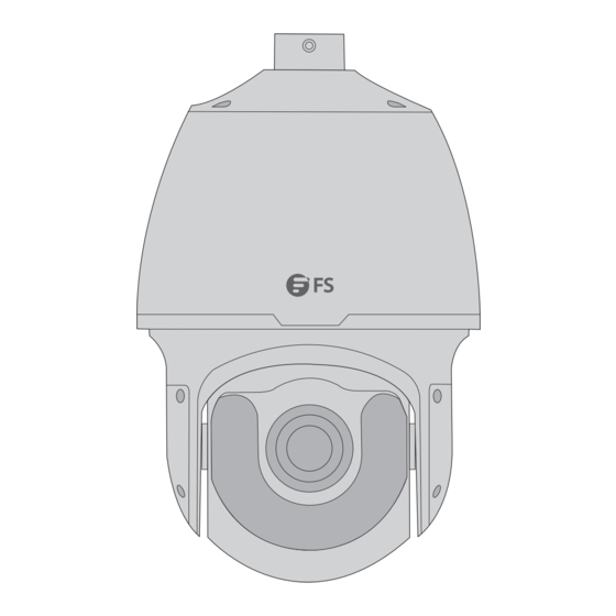
- Page 2 Introduction Thank you for choosing IPC Series PTZ Cameras. This guide is designed to familiarize you with the structure of the cameras and describes how to deploy them in your network. IPC425-8M-P IPC204-2M-PD...
- Page 3 Accessories Power Adapter x1 Adapter Ring x1 Power Cable x1 Waterproof Kit x1 Wrench x1 IPC204-2M-PD Screw Kit x1 Waterproof Kit x1 Drill Template Sticker x1 NOTE: The accessories may vary from illustration, please prevail in kind.
-
Page 4: Hardware Overview
Hardware Overview IPC425-8M-P No. Interfaces Description Ethernet Interface Connect to the Ethernet cable A BNC connector, output the analog video signal to a display Video Out device Audio In Input the audio signal Audio Out Output the audio signal Alarm In 1/2 Input the alarm signal Alarm Out+/- Output the alarm signal... -
Page 5: Power Cable
IPC204-2M-PD Power cable Network cable... -
Page 6: Installation Requirements
Installation Requirements Precautions Use a power adapter or a PoE device that meets the requirements. Otherwise, the device may be damaged. Make sure the length of the power cable between the power adapter and the camera is not too long. Otherwise, the voltage of the camera will be lowered, causing the camera to work abnormally. If it is required to lengthen the power cable, lengthen the cable between the power adapter and the mains. -
Page 7: Installation
Installation Installing Micro SD Card (Optional) IPC425-8M-P Slot 1 Slot 2 Micro SD card Slot 3 Back cover IPC204-2M-PD... - Page 8 1. Remove the screws on the back cover and insert the Micro SD card into the slot. 2. Check that the sealing ring is in position. Put the back cover back in place, and tighten the screws. CAUTION: 1. Format the Micro SD card on the camera's Web interface before use. 2.
- Page 9 3. Insert the recommended SFP optical module. 4. Connect the optical ber and the optical module, and then mount the tail cable adapter back in place. NOTE: Make sure to connect the optical ber to the optical interface of the device tail cable correctly.
-
Page 10: Mounting The Camera
Mounting the Camera Wall Mounting IPC425-8M-P 1. Mark the positions of the holes by referring to the mount points on the bracket and lead the cable through the hole on the wall. Then drill holes and knock in the expansion bolts. 2. - Page 11 Bracket adapter screw Inner track Camera holder 4. Align the two holders on the camera top with the inner track on the bracket adapter, push up and turn the camera anti-clockwise until it makes contact with the bracket adapter screw. M5 screw 5.
- Page 12 NOTE: 1. When mounting the camera, please install the bracket adapter to the bracket rst and then mount the camera to the bracket. 2. Tighten all the screws to hold the dome securely. 3. For waterproo ng, apply sealant on the connection part between the dome and thebracket, wall veneer slits, and cable outlets on the wall.
-
Page 13: Pendant Mounting
4. Lead self-tapping screws through the guide holes in the camera base and x them on the wall using a screwdriver. NOTE: During the wiring process, do not hold the tail cable for weight bearing. Otherwise, the cable connection might be loose. Pendant Mounting IPC204-2M-PD 1. - Page 14 2. Use a φ6-6.5mm drill bit to drill 30mm-depth guide holes according to the positions marked by the sticker. 3. Knock the wall plugs into the guide holes. 4. Loosen the screws on both sides of the mounting bracket, rorate the bracket 180° and straighten it, and then tighten the screws.
- Page 15 Align the holes with the self-tapping screws 5. Insert two self-tapping screws into the holes in the ceiling and secure them. Align the holes in the bracket base with the screws and hang the camera on the screws. CAUTION: Do not tighten the self-tapping screws completely, but make sure that they are secure enough to withstand the weight of the camera.
- Page 16 I nte r n e t Pro toco l Ve r s i on ( TC P / IP v 4 ) Pro p er tie s General Yo u c a n g e t I P s e t t i n g s a s s i g n e d a u t o m a t i c a l l y i f y o u r n e t w o r k s u p p o r t s t h i s c a p a b i l i t y .
-
Page 17: Online Resources
Product Warranty FS ensures our customers that for any damage or faulty items due to our workmanship, we will o er a free return within 30 days from the day you receive your goods. This excludes any custom-made items or tailored solutions. - Page 18 Einführung Vielen Dank, dass Sie sich für PTZ-Kameras der IPC-Serie entschieden haben. Diese Anleitung soll Sie mit dem Aufbau der Kamera vertraut machen und beschreibt, wie Sie sie in Ihrem Netzwerk einsetzen können. IPC425-8M-P IPC204-2M-PD...
- Page 19 Zubehör Netzadapter x1 Adapterring x1 Netzkabel x1 Wasserdichtes Set x1 Schlüssel x1 IPC204-2M-PD Schraubensatz x1 Wasserdichtes Set x1 Aufkleber Bohrschablone x1 HINWEIS: Das Zubehör kann von der Abbildung abweichen, bitte haben Sie Verständnis dafür.
- Page 20 Hardware-Übersicht IPC425-8M-P Nr. Schnittstellen Beschreibung Ethernet-Schnittstelle Verbindung zum Ethernet-Kabel Ein BNC-Steckverbinder, der das analoge Videosignal an Video-Aus ein Anzeigegerät ausgibt Audio-Ein Eingabe des Audiosignals Audio-Aus Ausgabe des Audiosignals Alarm-Ein 1/2 Eingabe des Alarmsignals Alarm-Aus+/- Ausgabe des Alarmsignals RS485 Verbindung zum RS485-Gerät Stromschnittstelle Verbindung zum Netzadapter Wird zur Erdung verwendet...
- Page 21 IPC204-2M-PD Stromkabel Netzwerkkabel...
-
Page 22: Wartung
Installationsvoraussetzungen Vorsichtsmaßnahmen Verwenden Sie einen Netzadapter oder ein PoE-Gerät, das den Anforderungen entspricht. Andernfalls kann das Gerät beschädigt werden. Achten Sie darauf, dass die Länge des Netzkabels zwischen dem Netzteil und der Kamera nicht zu lang ist. Andernfalls wird die Spannung der Kamera herabgesetzt, wodurch die Kamera nicht mehr richtig funktioniert. -
Page 23: Installation
Installation Einsetzen der Micro-SD-Karte (optional) IPC425-8M-P Steckplatz 2 Steckplatz 1 Micro SD-Karte Steckplatz 3 Hintere Abdeckung IPC204-2M-PD... - Page 24 1. Entfernen Sie die Schrauben an der hinteren Abdeckung und setzen Sie die Micro-SD-Karte in den Steckplatz ein. 2. Vergewissern Sie sich, dass der Sicherungsring in Position ist. Bringen Sie die hintere Abdeckung wieder an und ziehen Sie die Schrauben fest. ACHTUNG: 1.
- Page 25 3. Setzen Sie das empfohlene optische SFP-Modul ein. 4. Schließen Sie den Lichtwellenleiter und das optische Modul an und montieren Sie dann den End-Kabeladapter wieder an seinem Platz. HINWEIS: Achten Sie darauf, dass der Lichtwellenleiter korrekt an die optische Schnittstelle des Anschlusskabels des Geräts angesteckt wird. Installieren des wasserdichten Sets (optional)
-
Page 26: Montage Der Kamera
Installieren Sie das mitgelieferte wasserdichte Set am Ethernet-Kabel. HINWEIS: Bitte verwenden Sie zum Schutz des Kabels das selbstklebende wasserdichte Klebeband (separat erhältlich). Montage der Kamera Wandmontage IPC425-8M-P 1. Markieren Sie die Positionen der Löcher anhand der Befestigungspunkte an der Halterung und führen Sie das Kabel durch das Loch an der Wand. - Page 27 3. Befestigen Sie das Sicherheitskabel an der Halterung und an der Kuppel. Führen Sie das Heckkabel durch die Halterung. Schraube für Halterungsadapter Innere Schiene Kamerahalter 4. Richten Sie die beiden Halterungen an der Oberseite der Kamera an der inneren Schiene des Halterungsadapters aus, drücken Sie sie nach oben und drehen Sie die Kamera gegen den Uhrzeigersinn, bis sie die Schraube des Halterungsadapters berührt.
- Page 28 6. Schließen Sie die Kabel an und befestigen Sie die Halterung mit Unterlegscheiben, Federscheiben und Muttern an der Wand. HINWEIS: 1. Wenn Sie die Kamera montieren, bringen Sie bitte zuerst den Halterungsadapter an der Halterung an und montieren Sie dann die Kamera an der Halterung.
- Page 29 2. Bohren Sie mit einem φ6-6,5 mm Bohrer 30 mm tiefe Führungslöcher entsprechend den auf dem Aufkleber markierten Positionen. 3. Schlagen Sie die Dübel in die Löcher. 4. Führen Sie selbstschneidende Schrauben durch die Führungslöcher in der Kamerabasis und befestigen Sie sie mit einem Schraubenzieher an der Wand. HINWEIS: Halten Sie während der Verkabelung das Anschlusskabel nicht fest, um es zu entlasten.
- Page 30 Montage der Aufhängung IPC204-2M-PD 1. Kleben Sie die Bohrschablone an die Wand und richten Sie das Kreuz auf das Loch in der Wand aus. 2. Bohren Sie mit einem φ6-6,5 mm-Bohrer 30 mm tiefe Führungslöcher entsprechend den auf dem Aufkleber markierten Positionen. 3.
- Page 31 4. Lösen Sie die Schrauben auf beiden Seiten der Halterung, drehenSie die Halterung um 180°, richten Sie sie sie aus und ziehen Sie dann die Schrauben fest. Richten Sie die Löcher mit den selbstschneidenden Schrauben aus. 5. Setzen Sie zwei selbstschneidende Schrauben in die Löcher in der Decke ein und befestigen Sie sie.
- Page 32 6. Führen Sie zwei selbstschneidende Schrauben durch die verbleibenden zwei Löcher im Halterungsfuß und befestigen Sie sie an der Decke. Ziehen Sie alle Schrauben fest. ACHTUNG: Wenn Sie die Kamera an einem Mast oder einer Säule befestigen möchten, benötigen Sie einen Gurt (separat erhältlich). Kon gurieren der Kamera Schritt 1: Verbinden Sie den Computer und die Kamera über das gleiche LAN.
- Page 33 Kontakt https://www.fs.com/de/contact_us.html Produktgarantie FS garantiert seinen Kunden, dass wir bei Schäden oder fehlerhaften Artikeln, die auf unsere Verarbeitung zurückzuführen sind, eine kostenlose Rückgabe innerhalb von 30 Tagen nach Erhalt der Ware anbieten. Dies gilt nicht für Sonderanfertigungen oder maßgeschneiderte Lösungen.
- Page 34 Introduction Nous vous remercions d'avoir choisi les Caméras PTZ de la Série IPC. Ce guide a pour but de vous familiariser avec la caméra et décrit comment procéder à son déploiement. IPC425-8M-P IPC204-2M-PD...
- Page 35 Accessoires Adaptateur d'Alimentation x1 Anneau Adaptateur x1 Câble d'Alimentation x1 Kit Étanche x1 Clé x1 IPC204-2M-PD Kit de Vis x1 Kit Étanche x1 Autocollant du Schéma de Perçage x1 NOTE : Les accessoires peuvent varier par rapport à l'illustration, veuillez en tenir compte.
-
Page 36: Aperçu Du Matériel
Aperçu du Matériel IPC425-8M-P Numéro Interfaces Description Interface Ethernet Connexion au câble Ethernet Un connecteur BNC, pour la sortie du signal Sortie Vidéo vidéo analogique vers un dispositif d'a chage Entrée Audio Entrée du signal audio Sortie Audio Sortie du signal audio Entrée d'Alarme 1/2 Entrée du signal d'alarme Sortie d'Alarme+/-... - Page 37 IPC204-2M-PD Câble d'alimentation Câble réseau...
-
Page 38: Exigences D'installation
Exigences d’Installation Précautions à Prendre Utilisez un adaptateur d'alimentation ou un dispositif PoE conforme aux exigences. Sinon, l'appareil risque d'être endommagé. Assurez-vous que la longueur du câble d'alimentation entre l'adaptateur d'alimentation et la caméra n'est pas trop longue. Sinon, la tension de l'appareil sera réduite, ce qui entraînera un fonctionnement anormal de la caméra. - Page 39 Installation Installation de la Carte Micro SD (En Option) IPC425-8M-P Emplacement 2 Emplacement 1 Carte Micro SD Emplacement 3 Couvercle arrière IPC204-2M-PD...
- Page 40 1. Retirez les vis du couvercle arrière et insérez la carte Micro SD dans la fente. 2. Véri ez que le joint d'étanchéité est bien en place. Remettez le couvercle arrière en place et serrez les vis. ATTENTION : 1. Formatez la carte Micro SD sur l'interface Web de la caméra avant de l'utiliser.
- Page 41 3. Insérez le module optique SFP recommandé. 4. Connectez la bre optique et le module optique, puis remettez l'adaptateur de l’extrémité du câble en place. NOTE : Assurez-vous de connecter correctement la bre optique à l'interface optique de l'appareil. Installation du Kit Étanche (Optionnel)
-
Page 42: Installation De La Caméra
Installez le kit d'étanche fourni sur le câble Ethernet. NOTE : Veuillez utiliser la bande imperméable autocollante (achetée séparément) pour protéger le câble. Installation de la Caméra Fixation Murale IPC425-8M-P 1. Marquez la position des trous en vous référant aux points de xation sur le support et faites passer le câble par le trou sur le mur. - Page 43 3. Attachez le l de sécurité au support et au dôme. Et faites passer l’extrémité du câble à travers le support. Vis de l'adaptateur du support Voie interne Support de caméra 4. Alignez les deux supports sur la partie supérieure de la caméra avec le rail intérieur de l'adaptateur de support, poussez vers le haut et tournez la caméra dans le sens inverse des aiguilles d'une montre jusqu'à...
- Page 44 6. Connectez les câbles et xez le support au mur à l'aide de rondelles plates, de rondelles élastiques et d'écrous. NOTE : 1. Lors du montage de la caméra, veuillez d'abord installer l'adaptateur au support, puis monter la caméra sur le support. 2.
- Page 45 2. Utilisez une mèche de φ6-6.5mm pour percer des trous de guidage de 30mm de profondeur selon les emplacements marqués par l'autocollant. 3. Enfoncez les chevilles dans les trous de guidage. 4. Insérez des vis autotaraudeuses dans les trous de guidage de la base de la caméra et xez-les au mur à...
- Page 46 Installation de la Plaque de Suspension IPC204-2M-PD 1. Placez l'autocollant du schéma de perçage sur le mur ou plafond et alignez le centre de la croix sur le trou dans le mur. 2. Utilisez une mèche de φ6-6.5mm pour percer des trous de guidage de 30mm de profondeur selon les positions marquées par l'autocollant du schéma.
- Page 47 4. Desserrez les vis des deux côtés du support de montage, pivotez le support de 180° et redressez-le, puis serrez les vis. Alignez les trous avec les vis autotaraudeuses 5. Insérez deux vis autotaraudeuses dans les trous du mur ou plafond et xez-les. Alignez les trous de la base du support avec les vis et accrochez la caméra aux vis.
- Page 48 6. Faites passer deux vis autotaraudeuses dans les deux trous restants de la base du support et xez-les au plafond. Serrez les vis. ATTENTION : Une sangle (achetée séparément) est nécessaire si vous devez xer la caméra à un poteau ou à une colonne. Con guration de la Caméra Étape 1 : Connectez l'ordinateur à...
-
Page 49: Garantie Du Produit
Garantie du Produit FS garantit à ses clients que tout article endommagé ou défectueux dû à sa fabrication pourra être retourné gratuitement dans un délai de 30 jours à compter de la date de réception de la marchandise. Ceci exclut les articles faits sur mesure ou les solutions personnalisées. - Page 50 イントロダクション IPCシリーズPTZカメラをお選びいただきありがとうございます。このガイドは、カメラ の構造を理解し、ネットワークにカメラを導入する方法について説明することを目的とし ています。 IPC���-�M-P ��...
- Page 51 アクセサリー アダプタリング x� 電源アダプタ x� 電源ケーブル x� 防水キット x� レンチ x� IPC���-�M-PD ネジキット x� 防水キット x� ドリルテンプレートステッカー x� 注: アクセサリーはイラストと異なる場合がありますので、現物をご了承ください。 ��...
- Page 52 ハードウェア概要 IPC���-�M-P 番号 インターフェイス 説明 � イーサネッ トインターフェース イーサネッ トケーブルに接続する アナログビデオ信号をディ スプレイ装置に出力 � ビデオ出力 するBNCコネクタ � オーディオ入力 オーディオ信号を入力する � オーディオ出力 オーディオ信号を出力する � アラーム入力�/� アラーム信号を入力する � アラーム出力+/- アラーム信号を出力する � RS��� RS���デバイスに接続する � 電源インターフェース 電源アダプタに接続する � 接地用 ��...
- Page 53 IPC���-�M-PD 電源ケーブル ネットワークケーブル ��...
- Page 54 設置要件 注意事項 要件を満たす電源アダプターまたはPoEデバイスを使用して ください。 そうしないと、 デバイスが 破損する可能性があります。 電源アダプタとカメラの間の電源ケーブルの長さが長すぎないことを確認して ください。 さもない と、 カメラの電圧が低下し、 カメラの動作が異常になります。 電源ケーブルを長く する必要がある場 合は、 電源アダプタと主電源の間のケーブルを長く して ください。 テールケーブルを手で持って加重をかけないでください。 カメラのケーブルコネクターが緩む恐れ があります。 外部インターフェースに接続する場合は、 既存の接続端子を使用し、 ケーブル端子 (ラッチまたは クランプ) が良好な状態で適切に固定されていることを確認して ください。 ポートとの接触不良や、 衝撃や揺れによるケーブルの緩みを防ぐため、 余裕を持たせて取り付けて ください。 輸送中は、 カバーの摩擦、 傷、 汚れなどに十分注意して ください。 カバーを清潔に保つため、 実装中 はカバーの保護フィ...
- Page 55 設置 マイクロSDカードの取り付け(オプション) IPC���-�M-P スロット� スロット� マイクロSDカード スロット� バックカバー IPC���-�M-PD ��...
- Page 56 �. 背面カバーのネジを外し、 マイクロSDカードをスロッ トに挿入します。 �. シーリングリングが所定の位置にあることを確認します。 裏蓋を元の位置に戻し、 ネジを締めます。 ご注意: �. 使用前にカメラのウェブインターフェイスでマイクロSDカードをフォーマ ットしてください。 �. マイクロSDカードを抜き差しする際は、カメラやマイクロSDカードの破損を防ぐ ため、電源を切り、カメラの動作が停止するまでお待ちください。 �. 湿気の多い環境ではデバイスを分解しないでください。 SFP光モジュールの取り付け(オプション) IPC���-�M-P �. �本のネジを緩めてテールケーブルアダプタを外します。 防塵カバー �. テールケーブルアダプタ内部の防塵カバーを外します。 ��...
- Page 57 �. 推奨のSFP光モジュールを挿入します。 �. 光アイバと光モジュールを接続し、テールケーブルアダプタを元の位置 に取り付けます。 注: 光ファイバをデバイス・テール・ケーブルの光インターフェイスに正しく接続 してください。 防水キットの取り付け(オプション) 付属の防水キットをイーサネットケーブルに取り付けます。 注: ケーブル保護のため、自己粘着性防水テープ(別売)をご使用ください。 ��...
- Page 58 カメラの取り付け 壁取り付け IPC���-�M-P �. ブラケットの取り付けポイントを参照して穴の位置に印を付け、壁の穴にケーブルを通しま す。次に、ドリルで穴を開け、拡張ボルトを打ち込みます。 �. ブラケットアダプタ(G� ½ 雄ネジ)を回し、ブラケットアダプタをネジで固定します。 �. 安全ワイヤーをブラケットとドームに取り付けます。そしてテールケーブルをブラケットに 通します。 ��...
- Page 59 ブラケット アダプタネジ インナー トラック カメラ ホルダー �. カメラ上部の�つのホルダーをブラケットアダプタの内側トラックに合わせ、押し上げ、ブ ラケットアダプタのネジに接触するまでカメラを反時計回りに回します。 M� screw �. �本のM�ネジでドームを固定します。 ご注意: M�ネジは金属管に接触する程度に締めてください。締めすぎるとネジが 破損する恐れがあります。 �. ケーブルを接続し、ラットワッシャー、スプリングワッシャー、ナットでブラケットを壁に 取り付けます。 ��...
- Page 60 注: �. カメラを取り付ける際は、まずブラケットアダプタをブラケットに取り付 けてから、カメラをブラケットに取り付けてください。 �. すべてのネジを締めてドームをしっかりと固定します。 �. 防水対策として、ドームとブラケットの接続部、壁のベニヤスリット、壁のケ ーブル取出し口にシーリング材を塗布します。 �. 前述の方法では、テールケーブルは壁の中を通りますが、ケーブルを壁の中を 通したくない場合は、ベースのケーブルアウトレットにケーブルを通します。 IPC���-�M-PD �. ドリルテンプレートのステッカーを壁に貼り、クロスの中心を壁の穴に合わせます。 �. ステッカーのマーキング位置に合わせて、φ�~�.�mmのドリルビットを使用して深さ ��mmのガイド穴を開けます。 �. 壁面プラグをガイド穴に打ち込みます。 ��...
- Page 61 �. カメラベースのガイド穴にセルフタッピングネジを通し、ドライバーで壁に固定します。 注: 配線作業中は、テールケーブルを持って体重をかけないでください。ケーブル の接続が緩む恐れがあります。 ペンダント取り付け IPC���-�M-PD �. ドリルテンプレートのステッカーを壁に貼り、クロスの中心を壁の穴に合わせます。 ��...
- Page 62 �. シールの位置に合わせて、φ�~�.�mmのドリルで深さ��mmのガイド穴を開けます。 �. 壁面プラグをガイド穴に打ち込みます。 �. 取り付けブラケットの両側のネジを緩め、ブラケットを���°回転させてまっすぐにしてから ネジを締めます。 ��...
- Page 63 セルフタッピングネジで穴の位置を合わせる �. �本のタッピングねじを天井の穴に挿入して固定します。ブラケットベースの穴をネジに合 わせて、カメラをネジに掛けます。 ご注意: セルフタッピングネジは完全に締めず、カメラの重量に耐えられるよう十分 に締めてください。 �. ブラケットベースの残りの�つの穴にセルフタッピンねじ�本を通し、天井に固定します。 すべてのネジを締めます。 ご注意: カメラをポールや柱に取り付ける場合は、ストラップ(別売り)が必要です。 ��...
- Page 64 カメラの設定 ステップ�: パソコンとカ メラを同一LAN上に接続します。始める前に、パソコンにInternet Explorer �.�以降がインストールされていることを確認してください。 ステップ�: コンピュータのIPアドレスを ���.���.�.x に設定します。(「x」は � ~ ��� の任 意の数字です。) I nte r n et Proto co l Ve r si o n ( TC P / IP v 4 ) Pro p er tie s General Yo u c a n g e t I P s e t t i n g s a s s i g n e d a u t o m a t i c a l l y i f y o u r n e t w o r k s u p p o r t s t h i s c a p a b i l i t y.
- Page 65 �. 初回ログイン時にプラグインのインストールが必要な場合があります。画面の指示 に従ってインストールを完了し、再度ブラウザを開いてログインしてください。 �. デフォルトのパスワードは、初回ログイン時のみのものです。セキュリティを確保 するため、初回ログイン後にパスワードを変更してください。数字、文字、特殊文字 の�つの要素をすべて含む、少なくとも�文字の強力なパスワードを設定することを 強くお勧めします。 �. パスワードが変更されている場合は、新しいパスワードでログインしてください。 オンラインリソース ダウンロード https://www.fs.com/jp/products_support.html ヘルプセンター https://www.fs.com/jp/service/fs_support.html お問い合わせ https://www.fs.com/jp/contact_us.html 製品保証 FSは、 お客様が弊社の仕上がりに起因する損傷または不良品について、 製品を受け取った日から�� 日以内に無料で返品できることを保証します。 これには、 カスタムメイドのアイテムやカスタマイズさ れたソリューションは含まれません。 保証: この製品には、 材料または製造上の欠陥に対する�年間の限定保証が付いてい � ます。 保証の詳細については、 以下のサイ トをご参照ください: https://www.fs.com/jp/policies/warranty.html 返品: 返品を希望される場合は、 以下のサイ トで返品方法に関する情報をご確認く ださい: https://www.fs.com/jp/policies/day_return_policy.html ��...
-
Page 66: Compliance Information
2014/35/EU, 2011/65/EU und (EU)2015/863 konform ist.Eine Kopie der EU-Konformitätserklärung nden Sie unter www.fs.com/de/company/quality_control.html. FS.COM GmbH déclare par la présente que cet appareil est conforme à la Directive 2014/30/EU,2014/35/EU, 2011/65/EU et (EU)2015/863 . Une copie de la Déclaration de Conformité de l'UE est disponible à l'adresse suivante https://www.fs.com/fr/company/quality_control.html... -
Page 67: Waste Electrical And Electronic Equipment (Weee)
UKCA Hereby, FS.COM Innovation Ltd declares that this device is in compliance with the Directive SI 2016 No. 1091, SI 2016 No. 1101 and SI 2012 NO. 3032. FS.COM INNOVATION LTD Unit 8, Urban Express Park, Union Way, Aston, Birmingham, B6 7FH, United Kingdom.
Need help?
Do you have a question about the IPC Series and is the answer not in the manual?
Questions and answers