Table of Contents

Subscribe to Our Youtube Channel
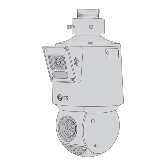
Related Manuals for FS IPC325-4M-PD


Summary of Contents for FS IPC325-4M-PD
- Page 1 IPC325-4M-PD PTZ DOME NETWORK CAMERA PTZ DOME Netzwerkkamera CAMÉRA RÉSEAU DÔME PTZ PTZドーム型ネッ トワークカメラ Quick Start Guide V1.0 Quick Start Anleitung Guide de Démarrage Rapide クイックスタートガイド...
- Page 2 Introduction Thank you for choosing the PTZ Dome Network Camera. This guide is designed to familiarize you with the structure of the camera and describes how to deploy it in your network. IPC325-4M-PD Accessories Power Adapter x1 Waterproof Kit x1...
-
Page 3: Hardware Overview
Optional (Not Included) PTZ Dome Wall Mount (CA-WP314) x1 Hardware Overview Name Description Power Interface Connect to the DC 12V power Audio In Input the audio signal Audio Out Output the audio signal Alarm In Input the alarm signal Alarm Out Output the alarm signal RS485 Interface Connect to a third-party device for communication... -
Page 4: Installation Requirements
Installation Requirements Precautions Use a power adapter or a PoE device that meets the requirements. Otherwise, the device may be damaged. Make sure the length of the power cable between the power adapter and the camera is not too long, otherwise the camera might work abnormally because of the lowered voltage. If necessary, lengthen the cable between the power adapter and the mains. -
Page 5: Installation
Installation Inserting the SD Card (Optional) Remove the slot cover of the camera to insert the Micro SD card (purchased separately). NOTE: 1. Please format the Micro SD card on the camera's Web interface before use. 2. Please consult your dealer or technical support for the recommended SD card speci cations. -
Page 6: Mounting The Camera
Mounting the Camera NOTE: 1. Concealed installation or open installation could be chosen as needed. The following part takes concealed installation as an example, which requires you to drill a hole on the wall so the cables can be hidden and led out from the wall. You may also choose not to drill the cable hole by leading the cables from the side outlet of the bracket directly. - Page 7 Safety Wire 3. Attach the safety wire to the bracket. Lead the tail cables through the bracket adapter and out from the bracket. Cross Recessed Pan Head Screw Notch 4. Attach the camera to the bracket adapter. Align the cross recessed pan head screw on the bracket adapter with the notch on the camera, then push up and rotate the camera clockwise till it is blocked.
- Page 8 M5 Screw 5. Tighten the two M5 screws on the bracket adapter. 6. Connect all cables and replace the bracket cover.
-
Page 9: Connecting The Power
Connecting the Power PoE Device Use an Ethernet cable to connect the Ethernet interface of the camera to the PoE port on a PoE device, such as a PoE switch or a PoE NVR. Power Adapter Use the power adapter to connect the power interface of the camera to the local power source. - Page 10 1. Connect the device and a computer to the same network segment. 2. Set the IP address of the computer to 192.168.1.x ("x" is any number from 2 to 254). 3. Open a web browser, type http://192.168.1.13 and enter the default username and password, admin/admin. IPC325-4M-PD Username admin Password...
-
Page 11: Online Resources
Product Warranty FS ensures our customers that for any damage or faulty items due to our workmanship, we will o er a free return within 30 days from the day you receive your goods. This excludes any custom-made items or tailored solutions. - Page 12 Einführung Vielen Dank, dass Sie sich für die PTZ Dome Netzwerkkamera entschieden haben. Diese Anleitung soll Sie mit dem Aufbau der Kamera vertraut machen und beschreibt, wie Sie sie in Ihrem Netzwerk einsetzen können. IPC325-4M-PD Zubehör Netzkabel x1 Netzadapter x1...
- Page 13 Optional (nicht im Lieferumfang enthalten) PTZ Dome Wandhalterung (CA-WP314) x1 Hardware-Übersicht Name Beschreibung Stromschnittstelle Anschluss an den DC-Strom mit 12 V Audio Eingang Eingang des Audiosignals Audio Ausgang Ausgang des Audiosignals Alarm Eingang Eingang des Alarmsignals Alarm Ausgang Ausgang des Alarmsignals RS485-Schnittstelle Verbindung mit einem externen Gerät zur Kommunikation Ethernet-Schnittstelle...
- Page 14 Installationsanforderungen Vorsichtsmaßnahmen Verwenden Sie einen Netzadapter oder ein PoE-Gerät, das die Anforderungen erfüllt. Andernfalls kann das Gerät beschädigt werden. Vergewissern Sie sich, dass die Länge des Netzkabels zwischen dem Netzadapter und der Kamera nicht zu lang ist, da die Kamera sonst aufgrund der niedrigeren Spannung möglicherweise nicht richtig funktioniert.
- Page 15 Installation Einsetzen der SD-Karte (optional) Entfernen Sie die Steckplatzabdeckung der Kamera, um die Micro-SD-Karte (separat erhältlich) einzulegen. HINWEIS: 1. Bitte formatieren Sie die Micro-SD-Karte vor der Verwendung über die Webschnittstelle der Kamera. 2. Erkundigen Sie sich bei Ihrem Händler oder dem technischen Kundendienst nach den empfohlenen Spezi kationen der SD-Karte.
-
Page 16: Montage Der Kamera
Montage der Kamera HINWEIS: 1. Sie können je nach Bedarf zwischen verdeckter und o ener Installation wählen. Im Folgenden wird die verdeckte Installation als Beispiel genommen, bei der Sie ein Loch in die Wand bohren müssen, damit die Kabel verdeckt aus der Wand geführt werden können. - Page 17 Sicherheitsdraht 3. Befestigen Sie den Sicherheitsdraht an der Halterung. Führen Sie die hinteren Kabel durch den Halterungsadapter und aus der Halterung heraus. Kreuzschlitzschraube mit Kerbe Notch 4. Bringen Sie die Kamera am Halterungsadapter an. Richten Sie die Kreuzschlitz-Schwenkkopfschraube am Halterungsadapter auf die Kerbe an der Kamera aus, drücken Sie sie nach oben und drehen Sie die Kamera im Uhrzeigersinn, bis sie blockiert ist.
- Page 18 M5-Schraube 5. Ziehen Sie die beiden M5-Schrauben am Halterungsadapter fest. 6. Schließen Sie alle Kabel an und bringen Sie die Abdeckung der Halterung wieder an.
-
Page 19: Anschließen Der Stromversorgung
Anschließen der Stromversorgung PoE-Gerät Verbinden Sie die Ethernet-Schnittstelle der Kamera über ein Ethernet-Kabel mit dem PoE-Port eines PoE-Geräts, z. B. eines PoE-Switches oder eines PoE-NVR. Netzadapter Verwenden Sie den Netzadapter, um die Stromschnittstelle der Kamera mit der örtlichen Stromquelle zu verbinden. - Page 20 2. Stellen Sie die IP-Adresse des Computers auf 192.168.1.x ein ("x" ist eine beliebige Zahl von 2 bis 254). 3. Ö nen Sie einen Webbrowser, geben Sie http://192.168.1.13 ein und geben Sie den Standard-Benutzernamen und das Standard-Passwort admin/admin ein. IPC325-4M-PD Username admin Password...
- Page 21 Kontakt https://www.fs.com/de/contact_us.html Produktgarantie FS garantiert seinen Kunden, dass wir bei Schäden oder fehlerhaften Artikeln, die auf unsere Verarbeitung zurückzuführen sind, eine kostenlose Rückgabe innerhalb von 30 Tagen nach Erhalt der Ware anbieten. Dies gilt nicht für Sonderanfertigungen oder maßgeschneiderte Lösungen.
- Page 22 Introduction Nous vous remercions d'avoir choisi la caméra Dôme Réseau PTZ. Ce guide est conçu pour vous familiariser avec la caméra et décrit comment procéder à son installation. IPC325-4M-PD Accessoires Adaptateur d'Alimentation x1 Kit d'Étanchéité x1 Câble d'Alimentation x1 Adaptateur de Support x1 Clé...
- Page 23 En Option (Non Inclus) Support Mural pour Caméra Dôme PTZ (CA-WP314) x1 Hardware Overview Désignation Description Interface d'Alimentation Connexion pour l'alimentation 12V DC Entrée Audio Entrée du signal audio Sortie Audio Sortie du signal audio Entrée d'Alarme Entrée du signal d'alarme Sortie Alarme Sortie du signal d'alarme Interface RS485...
-
Page 24: Conditions D'installation
Conditions d'Installation Précautions Utilisez un adaptateur d'alimentation ou un dispositif PoE conforme aux exigences. Dans le cas contraire, l'appareil risque d'être endommagé. Assurez-vous que la longueur du câble d'alimentation entre l'adaptateur d'alimentation et la caméra n'est pas trop longue, sinon la caméra pourrait fonctionner de manière anormale en raison de la baisse de tension. - Page 25 Installation Insertion de la Carte SD (en option) Retirez le couvercle de la fente de la caméra pour insérer la carte Micro SD (achetée séparément). NOTE : 1. Veuillez formater la carte Micro SD sur l'interface Web de la caméra avant de l'utiliser.
-
Page 26: Montage De La Caméra
Montage de la Caméra NOTE : 1. Une installation dissimulée ou une installation non dissimulée peut être choisie en fonction des besoins. La partie suivante prend pour exemple l'installation dissimulée, qui nécessite de percer un trou dans le mur a n de cacher les câbles et de les faire sortir du mur. - Page 27 Fil de Sécurité 3. Attachez le câble de sécurité au support. Faites passer les câbles de queue par l'adaptateur du support et faites-les sortir du support. Vis à Tête Cylindrique Cruciforme Entaille 4. Fixez la caméra à l'adaptateur de support. Alignez la vis à tête cylindrique cruciforme de l'adaptateur de support avec l'encoche de la caméra, puis poussez vers le haut et tournez la caméra dans le sens des aiguilles d'une montre jusqu'à...
- Page 28 Vis M5 5. Serrez les deux vis M5 sur l'adaptateur de support. 6. Connectez tous les câbles et remettez le couvercle du support en place.
-
Page 29: Connexion De L'alimentation
Connexion de l'Alimentation Dispositif PoE Utilisez un câble Ethernet pour connecter l'interface Ethernet de la caméra au port PoE d'un dispositif PoE, tel qu'un switch PoE ou un NVR PoE. Adaptateur d'Alimentation Pour brancher l'interface d'alimentation de la caméra à la source d'alimentation locale, utilisez l'adaptateur d'alimentation. -
Page 30: Connexion À La Caméra
2. Réglez l'adresse IP de l'ordinateur sur 192.168.1.x ("x" est un nombre quelconque compris ntre 2 et 254). 3. Ouvrez un navigateur web, tapez http://192.168.1.13 et entrez le nom d'utilisateur et le mot de passe de défaut, admin/admin. IPC325-4M-PD Username admin Password... -
Page 31: Garantie Du Produit
Garantie du Produit FS garantit à ses clients que tout article endommagé ou défectueux en raison de sa fabrication pourra être retourné gratuitement dans un délai de 30 jours à compter de la date de réception de la marchandise. Cette garantie ne s'applique pas aux articles fabriqués sur mesure ou aux solutions personnalisées. - Page 32 イン トロダクション このたびは、 PTZドーム型ネッ トワークカメラをお買いあげいただき、 誠にありがとうございます。 本ガイドは、 カメラの構造とネッ トワークへの導入方法について説明します。 IPC325-4M-PD アクセサリー 電源コード x� 電源アダプタ x� 防水用部品 x� ブラケッ トアダプタ x� レンチ x� 注:付属品は写真と異なる場合がございますので、 現物をご確認ください。 注:この電源コードは、ACアダプタ専用です。この電源コードは、他の機器には使 用しないでください。また、この電源コードを他のACアダプタに使用しないでくだ さい。...
- Page 33 オプション (別売り) PTZドームウォールマウン ト (CA-WP���) x� ハードウェアの概要 番号 名称 説明 電源インターフェース DC ��V電源に接続する オーディオイン 音声信号を入力する オーディオアウ ト 音声信号を出力する アラームイン アラーム信号を入力する アラームアウ ト アラーム信号を出力する RS���インターフ 通信のためにサードパーティのデバイスに接続する ェース イーサネッ トインタ イーサネッ トケーブルに接続する ーフェース マイクロSD マイクロSDカード (別途購入) を挿入し、 ローカルストレ カードスロッ ト ージを取得する ボタンを��秒間押し続けると、 工場出荷時のデフ ォルト 設定に戻ります。...
- Page 34 設置要件 注意事項 要件を満たす電源アダプタまたは PoE デバイスを使用して ください。 そうしないと、 デバイスが 損傷する可能性があります。 電源アダプタとカメラ間の電源ケーブルの長さが長すぎないように注意して ください。 長すぎる と、 電圧低下によりカメラが異常動作する可能性があります。 必要に応じて、 電源アダプタと主 電源の間のケーブルを延長して ください。 ケーブルの接触不良による故障の原因となりますので、 ケーブルを過度に曲げて設置しないで ください。 外部インターフェースに接続する場合は、 既存の接続端子を使用し、 ケーブルの端子 (ラッチま たはクランプ) が良好な状態で正し く固定されていることを確認して ください。 取り付け中にカバーの保護フィ ルムを剥がさないでください。 取り付け完了後、 装置の電源を 入れる前にフィ ルムを剥がして ください。 ポートとの接触不良や衝撃 ・ 揺れによるケーブルの緩みを防ぐため、 余裕を持った取り付けを 行い、...
- Page 35 設置 SDカードの挿入 (オプション) カメラのスロッ トカバーを取り外し、 マイクロSDカード (別売り) を挿入します。 注: �. 使用前にカメラのWeb インターフェイスでマイクロSDカードをフ ォーマッ トして く ださい。 �. SDカードの推奨仕様については、 営業担当またはテクニカルサポートにお問い合わせ ください。 注意: �. マイクロSDカード挿入した後はホットプラグしないでください。 �. マイクロSDカードを挿入または取り外す前に、必ず電源を切り、カメラの動作が 停止するまで待ってください。 そうしないと、カメラまたはマイクロSDカードが 破損する可能性があります。 �. 高湿環境では分解しないでください。カメラ内部の湿度が高いとレンズが曇る原因 となります。 防水キッ ト (オプション) の取り付け 付属の防水キットをイーサネットケーブル/DCケーブルに取り付けます。 注: ケーブルの保護には粘着防水テープ (別売) をご使用ください。...
- Page 36 カメラのマウン ト 注: �. 必要に応じて、 隠蔽設置またはオープン設置を選択できます。 以下では、 ケーブルを 隠して壁から引き出すことができるように、 壁に穴を開ける必要がある隠蔽設置を例にと って説明します。 また、 ケーブル穴を開けずに、 ブラケッ トの側面出口からケーブルを直接 引き出すこともできます。 �. 壁がカメラの重量を支えるのに十分な強度があることを確認して ください。 �. 事前に工具とハードウェア付属品をして ください。 注意: �. ブラケットとブラケットアダプターを含む、ドームカメラに接続するあらゆ る接続部のネジをすべて締めます。 �. ドームとブラケットの接続部分、壁のベニヤのスリット、壁面のケーブル取り出 し口などは必ず防水対策を行ってください。 ブラケットカバー �. 壁に穴を開け、ブラケット(別売り)を壁に取り付けます。ブラケットのカバーを取り外し、 ケーブルをブラケットに通します。 ブラケットアダプタ �. ブラケットアダプタをブラケットのコネクタにねじ込み、固定ネジを締めます。...
- Page 37 安全ワイヤー �. 安全ワイヤーをブラケットに取り付けます。 テールケーブルをブラケットアダプタを通して ブラケットから引き出します。 十字穴付きなべ小ねじ ノッチ �. カメラをブラケットアダプタに取り付けます。 ブラケットアダプタの十字穴付きナベネジを カメラのノッチ(切り欠き)に合わせ、カメラを押し上げて時計回りに引っ掛かるまで回転さ せます。 注: 天井に穴を開けないように、 カメラの側面スロッ ト開口部にケーブルを通してケーブル を固定します。...
- Page 38 M�ネジ �. ブラケットアダプタの�本のM�ネジを締めます。 �. すべてのケーブルを接続し、ブラケットカバーを取り付けます。...
- Page 39 電源を接続する PoEデバイス イーサネットケーブルを使用して、カメラのイーサネットインターフェイスをPoEスイッチや PoE NVRなどのPoEデバイスのPoEポートに接続します。 電源アダプタ 電源アダプタを使用して、カメラの電源インターフェイスをローカル電源に接続します。...
- Page 40 カメラの設定 �. コンピュータとデバイスを同じネッ トワークセグメン トに接続します。 �. コンピュータのIPアドレスを���.���.�.x に設定します("x"は�から���までの任意の数字) 。 �. ブラウザを開き、 「 http://���.���.�.��」 と入力し、 デフ ォルトのユーザー名とパスワード 「admin/admin」 を入力します。 IPC325-4M-PD Username admin Password Forgot Password? ***** Live View Login Reset �. Loginをクリ ックすると、 ウェブベースの設定ページが表示されます。...
- Page 41 オンラインリソース ダウンロード https://www.fs.com/jp/products_support.html ヘルプセンター https://www.fs.com/jp/service/fs_support.html お問い合わせ https://www.fs.com/jp/contact_us.html 製品保証 FSは、当社の管理による破損や不良品があった場合、お客様のお手元に商品が届いてから��日 以内であれば、特注品やオーダーメイドを除き、無料で返品及び交換を承ります。 保証:この製品は、材料または製造上の欠陥に対して�年間の限定保証を提供いたしま す。保証の詳細については、下記をご参照ください。 https://www.fs.com/jp/policies/warranty.html 返品 ・ 交換 : 返品及び交換を希望される場合、 方法については下記をご参照ください https://www.fs.com/jp/policies/day_return_policy.html...
-
Page 42: Compliance Information
2014/35/EU, 2011/65/EU und (EU)2015/863 konform ist. Eine Kopie der EU-Konformitätserklärung nden Sie unter www.fs.com/de/company/quality_control.html. FS.COM GmbH déclare par la présente que ce dispositif est conforme à la Directive 2014/30/EU, 2014/35/EU, 2011/65/EU et (EU)2015/863. Une copie de la Déclaration de Conformité de l'UE est disponible à l'adresse suivante https://www.fs.com/fr/company/quality_control.html. - Page 43 - 3 (a) / nmb - 3 (a). UKCA Hereby, FS.COM Innovation Ltd declares that this device is in compliance with the Directive SI 2016 No. 1091, SI 2016 No. 1101 and SI 2012 NO. 3032.
- Page 44 If you think batteries could have been swallowed or placed inside any part of the body, seek immediate medical attention. Q.C. PASSED Copyright © 2023 FS.COM All Rights Reserved.
Need help?
Do you have a question about the IPC325-4M-PD and is the answer not in the manual?
Questions and answers