
Related Manuals for FS S1900-5TP


Summary of Contents for FS S1900-5TP
- Page 1 S1900-5TP Switch Hardware Installation and Maintenance Guide V1.0.2307A Innovation · Expertise · Agility...
-
Page 2: Safety Statement
Preface Audience This document is intended for network engineers responsible for S1900-5TP switch installation and maintenance. You should have experience in network device installation and maintenance. Feature Statement Please visit the FS.COM Technical Documents page to download the datasheet and obtain information on the specifications supported by the product. -
Page 3: Table Of Contents
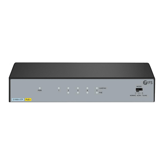
Contents Hardware Installation and Parts Replacement 1.1 Installation Procedure 1.2 Installation Preparation 1.3 Installing a Switch 1.4 Device Connection 1.5 Post-Installation Checks Innovation · Expertise · Agility... - Page 4 Hardware Installation and Parts Replacement The FS S1900-5TP is a 5-port Gigabit unmanaged multimode PoE Ethernet switch. It provides 5 10/100/1000Mbps RJ-45 adaptive ports, supporting line- speed forwarding on all ports. Additionally, it can be manually switched between VLAN normal mode and VLAN monitoring mode.
-
Page 5: Installation Procedure
• Mounting the Switch on a Wall: Anti-static bracelet (or gloves), ladder, screwdriver, marker, impact drill, rubber mallet 1.2.1 Checking the Installation Site The S1900-5TP switch must be used indoors. To ensure normal operations and long service life of the device, the installation site must meet the following requirements. Item... -
Page 6: Installation Precautions
Dust-free paper and fiber end-face microscope Meters Multimeter, bit error rate tester (BERT), and optical power meter The S1900-5TP switch is delivered without a tool kit. You need to prepare a tool kit by yourself. • 1.2.3 Installation Precautions Please follow the instructions below to install the switch to avoid equipment damage and security threats caused by incorrect operation: •... -
Page 7: Installing A Switch
Hardware Installation and Parts Replacement Switch Hardware Installation and Maintenance Guide 1.3 Installing a Switch 1.3.1 Mounting the Switch on a Workbench Install the switch on a smooth desktop. Install the supplied rubber feet on the four corners of the bottom surface of the switch and place them in the designated locations on the desktop, reserving enough ventilation space for the switch to dissipate heat. - Page 8 Hardware Installation and Parts Replacement Switch Hardware Installation and Maintenance Guide Step 2: Insert the screws into the expansion tubes. Figure 3: Inserting Screws Step 3: Hang the switch on the two screws. Figure 4: Hanging the Switch Innovation · Expertise · Agility...
-
Page 9: Device Connection
Step 4: Installation is complete. Figure 5: Complete Installation 1.4 Device Connection 1.4.1 Connecting Power Cables The S1900-5TP switch power supply uses direct current (DC) input: Rated current: 1.25A • Rated voltage: 51V • The switch is powered by an external DC adapter with a power of 51V/1.25A. Please follow the steps... - Page 10 Hardware Installation and Parts Replacement Switch Hardware Installation and Maintenance Guide 1.4.2 Connecting Switch to Computer (NIC) or Other Devices Figure 6: Devices Connected to Switch Indicator Light Explanation: Color Status Meaning Continuous On Powered On Green Power Off Continuous On Corresponding port has a normal connection Corresponding port is not connected Link/ACT...
-
Page 11: Post-Installation Checks
Hardware Installation and Parts Replacement Switch Hardware Installation and Maintenance Guide 1.5 Post-Installation Checks • If the switch is installed in a rack, please check if the installation angle iron of the rack and the switch is secure. If it is installed on a workbench, check if there is sufficient ventilation space around the switch and if the workbench is stable. - Page 12 FS has invested resources in product R&D, quality control, intelligent manufacturing, industry-leading experts, professional technical support, and networking solutions. All is to provide customers with higher-performance, lower-power consumption, and the most cost-effective products, promoting clients' network upgrades. For more information and technical support, welcome to contact us at www.fs.com/contact_us...
Need help?
Do you have a question about the S1900-5TP and is the answer not in the manual?
Questions and answers