
Related Manuals for FS S3910-24TF


Summary of Contents for FS S3910-24TF
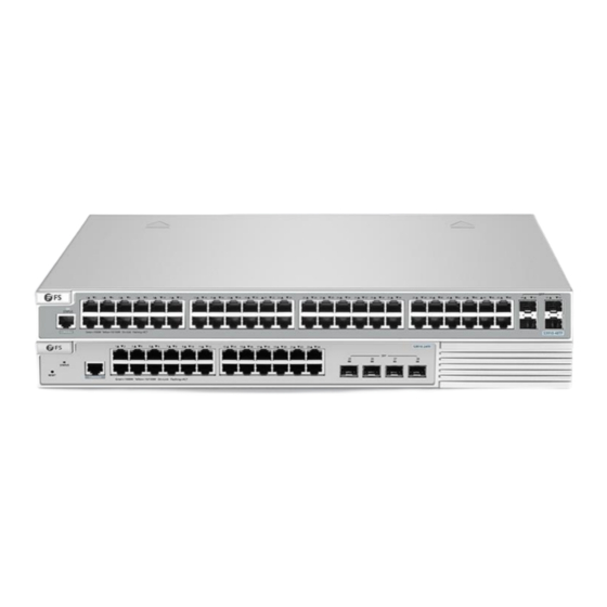
- Page 1 S3910-24TF & S3910-48TF Switches Hardware Installation and Maintenance Guide V1.0.2306A Innovation · Expertise · Agility...
- Page 2 Safety Statement: • To avoid harm to people and equipment, please read the safety recommendations in the Safety Precautions for FS Switches before installing the FS Switch. • Verify that the requirements described in the...
-
Page 3: Table Of Contents
Contents 1. Hardware Installation and Parts Replacement 1.1 Installation Procedure 1.2 Installation Preparation 1.3 Installing a Switch 1.4 Connecting a Switch 1.5 Post-Installation Checks 1.6 System Commissioning 1.7 Parts Replacement 2. Troubleshooting After Installation 2.1 Troubleshooting Flowchart 2.2 Common troubleshooting Innovation ·... -
Page 4: Hardware Installation And Parts Replacement
Hardware Installation and Parts Replacement S3910 series switch is FS.com's next-generation Gigabit Ethernet switch, providing with full Gigabit downlink and fixed 10 Gigabit uplink data interaction. This series of products adopt a brand-new hardware architecture design, equipped with FS.com's latest FSOS11.X modular operating system, offering larger resource... -
Page 5: Installation Procedure
Hardware Installation and Parts Replacement Switch Hardware Installation and Maintenance Guide 1.1 Installation Procedure Installation Connecting the System Mounting the Host Mounting the Host Preparation to the Grounding on the Cabinet on the Cabinet Connecting External Interface Bundle the Cables Inserting Various Connecting the Cables or Optical Cables... - Page 6 Hardware Installation and Parts Replacement Switch Hardware Installation and Maintenance Guide 1.2.2 Checking the Installation Site S3910-24TF & S3910-48TF switches must be used indoors. To ensure normal operations and long service life of the device, the installation site must meet the following requirements.
- Page 7 Hardware Installation and Parts Replacement Switch Hardware Installation and Maintenance Guide Procedure: Plan the available space before installing the cabinet. Maintain a clearance before the front and back doors for maintenance and operation. 2. Install and fasten the cabinet in the specified site as planned. 3.
-
Page 8: Installing A Switch
1.3 Installing a Switch 1.3.1 Mounting the Switch in a Cabinet or Rack The S3910-24TF & S3910-48TF switches can be installed in a standard 19-inch EIA rack. The installation process is as follows: Step 1:Remove the screws (included in the bracket packaging), and attach one end of the bracket to the switch, as shown in Figure 1. - Page 9 Hardware Installation and Parts Replacement Switch Hardware Installation and Maintenance Guide Figure 3: Rack-Mount Bracket Installation Diagram 3 1.3.2 Mounting the Switch on a Workbench In most cases, users do not have a standard 19-inch rack. Therefore, the most common method is to place the switch on a clean workbench.
- Page 10 • Pay attention to securing the external cables connected to the switch during installation to prevent the switch from detaching due to cable weight. The included mounting brackets of the S3910-24TF & S3910-48TF switches support wall-mount mode. The installation process is as follows: Step 1: Remove the screws (included in the front bracket packaging), and attach one end of the mounting bracket (rotated 90 degrees) to the switch, as shown in Figure 5.
-
Page 11: Connecting A Switch
Hardware Installation and Parts Replacement Switch Hardware Installation and Maintenance Guide The rear panel of the S3910 -24TF & S3910 -48TF switches hosts a grounded protective point . It should be connected to the grounding terminal of the rack first , and then the rack 's grounding terminal should be connected to the grounding busbar of the data center. - Page 12 Hardware Installation and Parts Replacement Switch Hardware Installation and Maintenance Guide Figure 7: Connecting the AC Power Cable Connect the other end of the AC power cable to the external AC power supply system. 1.4.2 Connecting Ethernet Cables Connect the RJ45 connector of an Ethernet cable to the management port on the equipment, and the other end to a network management switch or terminal.
- Page 13 Hardware Installation and Parts Replacement Switch Hardware Installation and Maintenance Guide Figure 8: Installing an Optical Module Keep the handle of the optical module closed, use your thumb and forefinger to hold two sides of the optical module, and gently pull the optical module. If the optical module is not pulled out, it has been correctly installed.
- Page 14 Hardware Installation and Parts Replacement Switch Hardware Installation and Maintenance Guide 4. Attach temporary labels to both ends of each high-speed cable and write numbers on the labels to identify the high-speed cables. 5. Connect high-speed cables to ports of the switch. - Find the ports matching the numbers on the high-speed cables and plug cable connectors to the ports.
-
Page 15: Post-Installation Checks
Hardware Installation and Parts Replacement Switch Hardware Installation and Maintenance Guide 1.4.6 Connecting the Grounding Cable There is one ground terminal on the back of the N8560-48BC switch chassis, which should be connected to the grounding lug of the rack first, and then connect the grounding lug to the grounding bar of the equipment room. -
Page 16: System Commissioning
Hardware Installation and Parts Replacement Switch Hardware Installation and Maintenance Guide • The grounding cables are connected properly. • The UTP and STP cables match with the interface type. • All cables are routed indoors. If not, check whether the power supply and interfaces are protected from lightning strikes. - Page 17 Hardware Installation and Parts Replacement Switch Hardware Installation and Maintenance Guide Step 2: Check the Serial Port Number Open Device Manager on the computer and check the serial port number. Step 3: Start Terminal Emulation Software on the Computer (Such as PUTTY) Innovation ·...
- Page 18 Hardware Installation and Parts Replacement Switch Hardware Installation and Maintenance Guide Step 4: Setting Terminal Parameters Parameter requirements: Baud rate is 9600, connection type is Serial, fill in COM port number according to the actual situation. The specific diagram is as follows. Figure 12: Setting Terminal Parameters 1.6.2 Powering On the Switch...
-
Page 19: Parts Replacement
Hardware Installation and Parts Replacement Switch Hardware Installation and Maintenance Guide 1.7 Parts Replacement 1.7.1 Replacing a Optical Module When replacing the optical module, pay attention to the following requirements: Anti-static preparations must be made before replacement. • Laser beams will cause eye damage. Do not look into bores of optical modules or optical fibers without eye •... - Page 20 Hardware Installation and Parts Replacement Switch Hardware Installation and Maintenance Guide Figure 13: LC/PC Connector Figure 14: MPO Connector 4. Pull out the optical module, plug the dustproof plug and dispose of it. - There are two types of buckles on the optical module. A pull-rod handle that needs to be turned over to open, as shown in Figure 15.
- Page 21 Hardware Installation and Parts Replacement Switch Hardware Installation and Maintenance Guide Figure 16: Handle-type Handle 5. Take out the new optical module from the package, and slowly insert it into the interface until you hear a "pop" sound, indicating that it has been installed in place. 6.
-
Page 22: Troubleshooting After Installation
Troubleshooting After Installation Innovation · Expertise · Agility... -
Page 23: Troubleshooting Flowchart
Check the LEDs on the device other modules other modules Check serial port connection Check serial port connection Check the cable connection Check the cable connection and parameters and parameters Contact FS Technical Support Contact FS technical support Innovation · Expertise · Agility... -
Page 24: Common Troubleshooting
Check the hyperterminal's serial port settings; they should match the configuration parameters mentioned in the Configuration Guide. If they differ, modify the serial port configuration. If you are still unable to see serial output, please contact FS technical support. Innovation · Expertise · Agility... - Page 25 First confirm whether the module is inserted in place. If everything is normal, but the newly inserted module still can not be powered on and works, please contact FS technical support. Fault 7: The link can not be set up between optical ports Fault Symptom The system runs normally.
- Page 26 FS has invested resources in product R&D, quality control, intelligent manufacturing, industry-leading experts, professional technical support, and networking solutions. All is to provide customers with higher-performance, lower-power consumption, and the most cost-effective products, promoting clients' network upgrades. For more information and technical support, welcome to contact us at www.fs.com/contact_us...
Need help?
Do you have a question about the S3910-24TF and is the answer not in the manual?
Questions and answers