Table of Contents
Advertisement
Quick Links
CAUTION!
This manual contains important information for the correct installation, operation and maintenance of the
equipment described herein. All persons involved in such installation, operation, and maintenance should be
thoroughly familiar with the contents. To safeguard against the possibility of personal injury or property damage,
follow the recommendations and instructions of this manual and keep it for further reference.
WARNING!
The equipment shown in this manual is intended for industrial use only and should not be used to lift, support, or
1
otherwise transport people.
Advertisement
Table of Contents

Subscribe to Our Youtube Channel
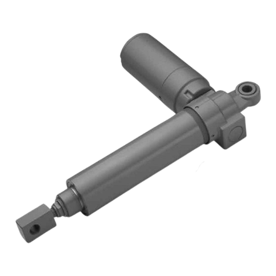
Summary of Contents for Duff-Norton 3405 Series
- Page 1 CAUTION! This manual contains important information for the correct installation, operation and maintenance of the equipment described herein. All persons involved in such installation, operation, and maintenance should be thoroughly familiar with the contents. To safeguard against the possibility of personal injury or property damage, follow the recommendations and instructions of this manual and keep it for further reference.
-
Page 2: Table Of Contents
Slip Clutch Assembly .........................6 Figure 4-2. Brake Coupling Alignment ......................7 Section V Technical Illustration and Parts List Table 5-1. Parts List for Duff-Norton 3405 and 6405 Series with Slip Clutch ...........8 Figure 5-1. Exploded Parts Illustration ......................9 Section VI Wiring Diagram Figure 6-1. -
Page 3: Introduction
Claims must be made used to lift, support or otherwise transport people unless within one year after date of shipment. Duff-Norton will you have a written statement from Duff-Norton which not repair or replace any parts that become inoperative authorizes the specific actuator unit, as used in your... -
Page 4: Installation
Note: Dimensions are subject to change without notice. Figure 1-1. Dimensions and Specificaions Section II Installation 2-1. 2-4. To install the actuator, simply support and secure The axes of the clevis pins should be parallel so it with a single pin through one clevis end, secure it that the actuator can pivot without binding. -
Page 5: Operational Precautions
Section IV Maintenance 4-1. Lubrication 2b. A.C. Unit Duff-Norton recommends the use of the following Remove socket head cap screws (1) and lubricant in conjunction with proper maintenance lock washers (2) from motor (3) and remove procedures of this unit: Mobil XHP461 or XHP462. -
Page 6: Assembly
disassembly of screw (25), nut (27) and translating coupling. Note if coupling is not damaged, it need tube (32) will not be necessary unless clutch must be not be removed. replaced. 24. A.C. unit - ball brake disassembly. Remove set 13. - Page 7 2. Assemble bearing (11) on pinion (12) and install 17. Fill translating tube (32) approximately half full with retaining ring (10) on pinion (12). Exxon Ronnex Extra Duty #1 grease. 3. Apply Loctite retaining compound (or equal) to OD 18. Assemble nut (27) into translating tube (32) (align of bushing (15) and install in housing (13) (assemble holes in translating tube with holes in nut).
-
Page 8: Technical Illustration And Parts List Table 5-1. Parts List For Duff-Norton 3405 And 6405 Series With Slip Clutch
Section V Parts List and Technical Illustration Table 5-1. Parts List for Duff-Norton 3405 and 6405 Series with Slip Clutch MPD-6405 (DC) SPB-6405 (AC) MPD-3405 (DC) SPB-3405 (AC) Index Part Name Quantity Part Quantity Part Required Number Required Number Screw... - Page 9 WARNING Use only replacement parts supplied by or approved by Duff-Norton. Non-authorized parts may be inadequate, resulting in serious injury or death in event of failure. Figure 5-1. Exploded Parts Illustration...
-
Page 10: Wiring Diagram
Section VI Wiring Diagram Figure 6-1. Limit Switch Wiring Diagram... - Page 11 Notes...
- Page 12 Fax: (704) 588-1994 Email: duffnorton@cmworks.com www.duffnorton.com 2017 © Yale Industrial Products, Inc., Duff-Norton Division ECO 99057 All rights reserved by Yale Industrial Products, Inc., Duff-Norton Division. SK-6405-100 May not be copied in whole or in part. PDF 01/17 Printed in the USA...


Need help?
Do you have a question about the 3405 Series and is the answer not in the manual?
Questions and answers