Table of Contents
Advertisement
Publication Part No. SK-2373-R
CAUTION
This manual contains important information for the correct installation, operation and maintenance of the
equipment described herein. All persons involved in such installation, operation, and maintenance should be
thoroughly familiar with the contents. To safeguard against the possibility of personal injury or property
damage, follow the recommendations and instructions of this manual and keep it for further reference.
®
WARNING
The equipment shown in this manual is intended for industrial use only and should not be used to lift, sup-
port, or otherwise transport people.
Advertisement
Table of Contents

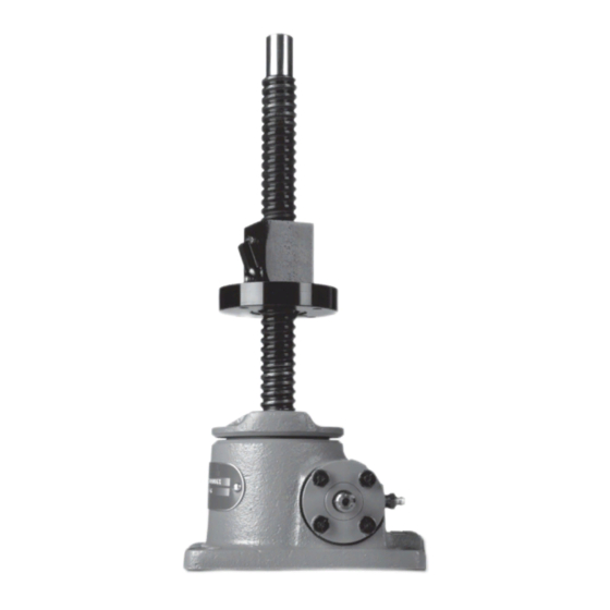
Summary of Contents for Duff-Norton UM28632
- Page 1 Publication Part No. SK-2373-R CAUTION This manual contains important information for the correct installation, operation and maintenance of the equipment described herein. All persons involved in such installation, operation, and maintenance should be thoroughly familiar with the contents. To safeguard against the possibility of personal injury or property damage, follow the recommendations and instructions of this manual and keep it for further reference.
-
Page 2: Table Of Contents
Contents Section I General Information ......................... 3 1-1. General............................3 1-2. Applications ..........................3 1-3. Table of Specifications ......................3 1-4. Dimensions ..........................4 Table 3. Upright Models ......................... 4 Table 4. Inverted Models ........................5 1-5. Important Precautions ....................... 6 1-6. -
Page 3: Section I
-20 to 200 ° F. If your environment is This manual contains maintenance instructions dirty and/or contains abrasive particles it is impor- for Duff-Norton® rotating ball screw actuators. It tant to protect the screw with a boot. If your atmo- describes and details procedures for installation,... -
Page 4: Dimensions
1-4. Dimensions Note: Ball nut must be kept from rotating to prevent it from self-lowering. Worm and gear set is not self-locking. Use brake on worm shaft or motor. Housing dimensions and base configurations vary. Table 3. Upright Models Drawing Model Number Ref. - Page 5 1-4. Dimensions (cont.) Note: Ball nut must be kept from rotating to prevent it from self-lowering. Worm and gear set is not self-locking. Use brake on worm shaft or motor. Housing dimensions and base configurations vary. Table 4. Inverted Models Drawing Model Number Ref.
-
Page 6: Important Precautions
Duff-Norton will not repair or replace any turn the main drive shaft by hand. If there are no parts that become inoperative because of improper... -
Page 7: Maintenance
Note rior lubricating properties affecting both wear life Disassembly should be accomplished on a clean and maximum duty cycle. Duff-Norton is not aware cloth. of an equivalent grease. If this grease is not 1. Disassembly Inspection (Refer to Figure 3-1). To... - Page 8 long enough to extend 1 1/2˝ to 2˝ beyond 6. Remove ball screw (5) and gear assembly (6) each end of the lifting nut. from shell. For ease in removing ball screw and gear assembly, loosen cap screws (9) holding Note flanges (11) and shift worm (14) slightly.
-
Page 9: Cleaning
Figure 2-2. Ball Nut Storage Arbor 16. Remove key (22) from ball screw (5). on their working or mating surfaces. 17. Remove spacer (23) from ball screw. 3. Check small common components (screws, etc.) and replace as required. Note On some models spacer is threaded. 4. - Page 10 away from ball screw threads. lockwashers (10). Care should be taken to prevent cutting of seal on worm keyway. 6. Thread locknut (20) on ball screw (5) and tighten securely against worm gear (6). Make certain For 1/2-Ton Models - Slide bushings (11a) over that this assembly is tightly drawn up.
- Page 11 20. Refer to Figure 2-2 for reassembly of lifting nut thread it onto ball screw (5). After lifting nut (24) from tube arbor to ball screw (5). is completely threaded onto ball screw, remove arbor from ball screw pilot. a. With lifting nut centered on arbor tube, grasp lifting nut and arbor to prevent lifting nut from Note running off of arbor, and remove binding...
-
Page 12: Illustrated Parts List
Section III Illustrated Parts List 3-1. General illustration is the index number. Keyed to this index This section contains an exploded illustration of number on the parts list is the part name the 2800 and 9800 Series rotating ball screw actua- tors. - Page 13 Figure 3-1. Exploded Illustration 2800 and 9800 Series Ball Screw Actuators...
- Page 16 ® P.O. Box 7010 Charlotte, NC 28241-7010 General Office (704) 588-0510 Customer Service (800) 477-5002 Customer Service (704) 588-4610 FAX (704) 588-1994 Email: duffnorton@cmworks.com SK-2373-R www.duffnorton.com © 2000 Yale Industrial Products, Inc. 500/1002...


Need help?
Do you have a question about the UM28632 and is the answer not in the manual?
Questions and answers