Table of Contents
Advertisement
Quick Links
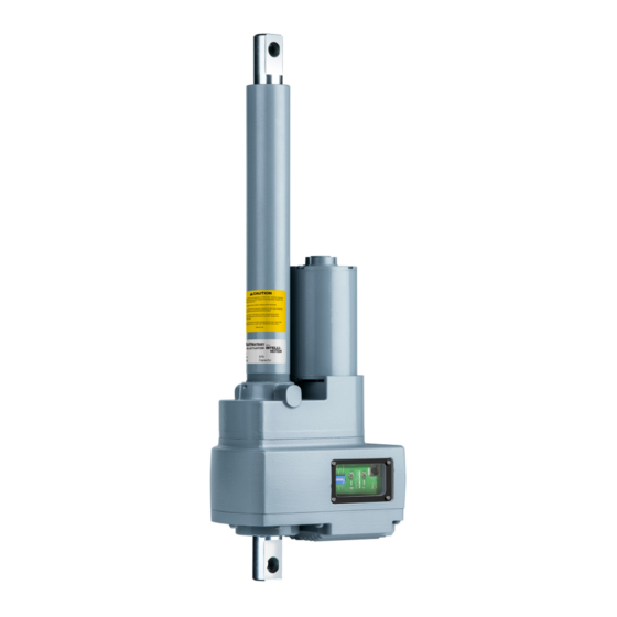
SPA A
with Intelli-Motion™ Technology
Installation, Operation &
Maintenance Instructions
Publication Part No. DN-SADG-01
This manual contains important information for the correct installation, operation and maintenance of the equipment
described herein. All persons involved in such installation, operation and maintenance should be thoroughly familiar
with the contents. To safeguard against the possibility of personal injury or property damage, follow the
recommendations and instructions of this manual and keep it for further reference.
The equipment shown in this manual is intended for industrial use only and should not be used to lift, support or
otherwise transport people.
May 2022 © Duff-Norton
®
CTUATOR
!
CAUTION
!
WARNING
Advertisement
Table of Contents

Subscribe to Our Youtube Channel
Related Manuals for Duff-Norton SPA Series


Summary of Contents for Duff-Norton SPA Series
- Page 1 WARNING The equipment shown in this manual is intended for industrial use only and should not be used to lift, support or otherwise transport people. May 2022 © Duff-Norton ®...
-
Page 2: Table Of Contents
Table of Contents Section 1 General Information General ..........................3 Applications ........................3 Factory Preparation ......................3 Warranty ..........................3 Dimensions and Specifications ..................4 Section 2 Installation Installation Procedures ....................8 Wiring Diagrams......................9 Analog I/O Adjustments ....................15 Limit Switch Adjustment ....................16 Setting the Actuator Speed ..................16 LED Indicators.......................16 Section 3 Configurator Software... -
Page 3: General Information
Limit switches are checked at the factory for proper functioning. 1.4 Warranty Subject to the conditions stated herein, Duff-Norton will repair or replace, without charge, any parts proven to Duff- Norton’s satisfaction to have been defective in material or workmanship. Claims must be made within one year after date of shipment. -
Page 4: Dimensions And Specifications
1.5 Dimensions and Specifications 1.5.1 Envelope and Mounting Dimensions 1.5.2 Specifications Mechanical Specifications Dynamic Rated Load 1,500 lbs (6.7 kN) Minimum Stroke Length* 6 in. (152 mm) Maximum Stroke Length* 24 in. (610 mm) Stroke Length Increments* 6 in. (152 mm) Maximum Speed at Dynamic Rated Load 0.83 in./sec (21 mm/sec) Duty Cycle Range at Dynamic Rated Load... - Page 5 Electrical Specifications Supply Voltage* 115 VAC, 1P , 50-60 Hz Current at No Load 2.0A +/- 15% Current at Dynamic Rated Load and Max. Duty Cycle 8.0A +/- 15% Control Voltage 24V DC +/- 30% Analog Input Range 0 - 10V DC or 4 - 20 mA, selectable Analog Output Range 0 - 10V DC or 4 - 20 mA, selectable Digital Inputs...
- Page 6 1.5.3 Ratings Graphs 1.5.3.1 Duty Cycle vs. Load (60 Hz) Duty Cycle vs. Load (60 Hz, 0.83 ips) 1000 1250 1500 Load (lbs) 1.5.3.2 Duty Cycle vs. Speed (at maximum rated load/Hz) Duty Cycle vs. Speed (At Absolute Maximum Load) 1500 1250 1000...
- Page 7 1.5.3.3 Load vs. Speed (30% Duty Cycle) Load vs. Speed (30% Duty Cycle) 1500 1250 1000 0.00 0.42 0.83 1.25 1.66 Speed (ips) 1.5.3.4 Absolute Maximum Load Per Hz vs. Speed Absolute Maximum Load vs. Speed (Duty Cycle Decreases Above 0.83 ips) 1500 1250 1000...
-
Page 8: Installation
2.1 Installation Procedures 2.1.1 Mechanical Installation Duff-Norton electromechanical actuators can be used in tension, compression or combination tension/compression applications. Examples of tension and compression appear on the right. Mount the actuator to avoid side loading and eccentric loading. To optimize the performance and life of the actuator, mount it so that the load is applied along the longitudinal axis of the translating tube. -
Page 9: Wiring Diagrams
Once the optimal mounting arrangement has been determined, mount Duff-Norton electromechanical actuators by slipping a solid pin through the translating tube clevis and rear housing clevis. The pins must be parallel to each other to avoid binding. The actuator restraining brackets and related hardware must be able to withstand the torque generated by the actuator as it extends and retracts. - Page 10 2.2.2 Base Model Analog and Digital Receptacle Part Number: MDC-12MR-4-1 Mating Part: MDCPM-12FP-XX* (17.5) 0.69 XX* = length Base Model Wiring Diagram Signal Receptacle M12 PIN 1 Extend Limit Reached Retract Limit Reached PIN 2 Healthy / Fault PIN 3 Moving PIN 4 DO Common...
- Page 11 2.2.3 Analog Model Analog Model Wiring Diagram Signal Receptacle M12 PIN 1 Extend Limit Reached Retract Limit Reached PIN 2 Healthy / Fault PIN 3 Moving (Ext/Retr Control) / In-Position (Analog Control) PIN 4 DO Common ØV PIN 5 +24V PIN 6 Enable PIN 7...
- Page 12 Base Analog Signal Signal Function Model Model Number DO 1 ±24V DC ±30% Extend Limit Reached DO 2 ±24V DC ±30% Retract Limit Reached DO 3 ±24V DC ±30% Fault DO 4 ±24V DC ±30% Dual Purpose: • Discrete mode: “moving” •...
- Page 13 Specification Value/Units Digital Inputs 3,150 Ohms Tolerance +/- 4% Voltage Range 15 - 32V DC, 24V DC Nominal ON Voltage >15V DC OFF Voltage <8V DC Maximum Voltage 40V DC Minimum ON Current 4.7 mA Maximum OFF Current 2.4 mA Digital Outputs Type Solid State Relay...
- Page 14 2.2.4 Ethernet Model Use an industrial Ethernet cable with female, 4-pole D-Coded M12 connector on the actuator end, MDE45-4FP-RJ45 series or equivalent. The connector on the other end will be determined by the requirements of the customer’s equipment (PLC, Ethernet switch, etc.). Connect the cable from the customer controller to the 1/4"...
-
Page 15: Analog I/O Adjustments
2.3 Analog I/O Adjustments Figure 2-6: Selector Switches Configure the Analog Input and Output using the selector switches on the User I/O board (behind the access cover on the actuator). Select the input or output to be V (0 - 10V DC) or mA (4 - 20 mA). The input may be configured differently from the output if preferred. -
Page 16: Limit Switch Adjustment
Position V DC Retract Limit 12.0 100% 10.0 20.0 Extend Limit Table 2-3: Analog Mode Scaling 2.4 Limit Switch Adjustment • The Extend Limit and Retract Limit are preset at the factory to prevent overtravel of the actuator. • Travel limits may be set inside of these boundaries according to the application needs. To set the limits from the User I/O board, simply operate the actuator to the preferred position for the Retract Limit, and press the R-Limit button. -
Page 17: Configurator Software
Section 3 Configurator Software 3.1 Installation To configure the actuator, install the Configurator software onto your PC. Connect the Configurator cable (USB to RJ-45) from the PC to the actuator, and apply power to the actuator. To select which COM port the SMART Actuator Configurator communicates over, select File -> Options. A pop-up window should appear with a drop-down box containing a list of all active COM ports. - Page 18 3.2.5 Ethernet The Ethernet tab displays the current network parameters and allows configuration of relevant ones. The IP address and subnet mask can be updated in this tab. The existing network parameters will stay in effect until a power cycle is performed.
-
Page 19: Operating Instructions
Section 4 Operating Instructions 4.1 Models with Discrete I/O Control Interface 4.1.1 Initial Setup Wire the actuator power supply according to the diagram in Figure 2-1 on page 9. Wire the digital and analog I/O to the PLC or other controls according to the diagram in Figure 2-2 on page 10 and Figure 2-3 on page 11. -
Page 20: Models With Ethernet I/P Control Interface
4.2 Models with Ethernet I/P Control Interface 4.2.1 Connecting Your SPA with Intelli-Motion The SPA with Intelli-Motion utilizes a static IP address for EthernetIP connections. The static IP address can be configured with the Configurator. Following the connection instructions in Section 4.2.1 on page 20, connect the SPA with Intelli-Motion to the Configurator. - Page 21 4.2.2 Adding the SPA with Intelli-Motion to a Studio 5000™ Project NOTE: This section of the manual (Adding the SPA with Intelli-Motion to a Studio 5000 Project) is for reference only. CMCO does not control Studio 5000 and changes to menus, look, or operation, could be made at any time. In Rockwell Studio 5000, create a new project or open the project that you would like to add the SPA with Intelli-Motion to.
- Page 22 In the new pop-up window, give the unit a name and type in the IP address of the iSPA. Click the “OK” button. At this point, if everything is set up properly, a PLC with this program should connect to the iSPA with Intelli-Motion, and the network LED on the user I/O board should blink.
- Page 23 In the Registration window, click the appropriate radio button. Use “Register a single file” if you are installing the EDS file as provided by CMCO. Locate the EDS file in the “Browse” menu and complete the Wizard. 4.2.4 Installing the User-Defined Data Type The iSPA with Intelli-Motion has a User-Defined Data Type (UDT) to make working with the iSPA simple and straightforward.
- Page 24 Under the “User-Defined” submenu, data types should appear. The iSPA001_UDT contains both the complete formatting for the data in both the control messages (Originator/PLC to Target/iSPA) and feedback messages (Target/iSPA to Originator/PLC). 4.2.5 Using the User-Defined Data Type (UDT) Use the User-Defined Data Type by creating a tag (based on the UDT), and implementing COP (copy) instructions to load/ push the I/O data to and from the iSPA with Intelli-Motion.
- Page 25 If any issues arise, ensure that the iSPA device that was added to the program has the data type set as SINT. Access options by right-clicking on the device and selecting “Properties.” Under the “General” tab, scroll to the bottom and select “Change,”...
- Page 26 4.2.6 EthernetIP Control and Feedback Data The iSPA with Intelli-Motion uses Class 1 I/O messaging for the control and feedback messages. The EDS gives the controller the assembly and instance data to connect. The following tables define the data contained in each message. The UDT, as described in Section 4.2.5 on page 24, provides a convenient way to access and update the specific feedback and control variables.
- Page 27 SMART Actuator Implicit / I/O Messaging Data Structures 32 Bytes/SINT Total Actual Order/Type Byte Order: Originator to Target (CONTROL MESSAGE) Name Eng Unit Description StartIndex(byte) Data Type ActiveLimitPair n/a: Selects which limit pair (or end of enumeration stroke) is active. End of stroke limits (0", stroke length) 1-4: Stored Limit Pair Number...
- Page 28 SMART Actuator Implicit / I/O Messaging Data Structures Actual Order/Type 60 Bytes/SINT Total Target to Originator (FEEDBACK MESSAGE) Byte Order: Name Eng Unit Description StartIndex(byte) Data Type DINT Total_Cycles counts 2147483647 Number of cycles the actuator has travelled DINT Total_Inches_ inches 2147483647 Total number of inches the Travelled...
- Page 29 SMART Actuator Implicit / I/O Messaging Data Structures Actual Order/Type 60 Bytes/SINT Total Target to Originator (FEEDBACK MESSAGE) Byte Order: Name Eng Unit Description StartIndex(byte) Data Type bit2 Retracting n/a: bool Actuator executing a retract movement bit3 Faulted n/a: bool Actuator is faulted bit4 At_Extend_Limit n/a: bool...
- Page 30 SMART Actuator Implicit / I/O Messaging Data Structures Actual Order/Type 60 Bytes/SINT Total Target to Originator (FEEDBACK MESSAGE) Byte Order: Name Eng Unit Description StartIndex(byte) Data Type bit6 RAM_Corruption n/a:bool RAM corruption has occured. Reset Required. bit7 Motor_Overheated n/a:bool Motor has reached maximum temperature bit8 Electronics_...
- Page 31 4.2.7 Control Modes The iSPA with Intelli-Motion has two main control modes, “Discrete” mode and “GOTO” mode. These two modes work very similar to the way a discrete model and an analog model would work, with the many benefits of EthernetIP. The ControlMode variable in the UDT/control message sets which control mode will be active.
- Page 32 The speed control limits must be set as well (LowerHzLimit, UpperHzLimit). They are also in units of Hz x100. These should be set to the appropriate values for the application. An example is an application that is consistently moving the maximum full load capacity and therefore should not increase the speed beyond 60Hz.
- Page 33 4.2.11 StatusBits Tag: Operation and Control Message Feedback In the input portion of the UDT, there is a tag named StatusBits. This tag accumulates useful bits for process control and troubleshooting. Many applications can utilize feedback from these status bits to accomplish the control objectives. Additionally, when programming, the latter half of the status bits are useful in determining if there is something that needs updating in the control message itself.
-
Page 34: Maintenance
Maintenance This product does not require regular maintenance for the life of the unit. 5.1 Lubrication Duff-Norton recommends using Mobilgrease™ XHP™ 462 lubricant in conjunction with performing proper maintenance procedures on this unit. 5.2 Required Tools Use a bearing puller, press, soft-jaw table clamp, and common hand tools for proper disassembly and assembly. - Page 35 WARNING WARNING Take care to avoid damaging the motor lead wires. 7. Remove the thrust washers (24 & 36) and thrust bearing (25). Note that these bearing sets may come off with the controls housing assembly (41) or they may stay with the spacer nut (27) and dowel pin (37). Inspect both locations to verify that you have accounted for all components.
- Page 36 5.4.2 SPA Actuator Assembly Instructions Assemble the actuator as follows while referring to Figure 5.1 on page 43. Read the instructions thoroughly before assembling the actuator. NOTICE Be sure all components are clean and dry before assembling. 1. Apply a small amount of Mobilgrease XHP 462 to both sides of the outer tube gasket (17). This will aid in installation and prevent damage to the gasket during the assembly process.
- Page 37 11. Thread the outer tube (31) into the housing (1). Continue threading the outer tube (31) into the housing (1) until approximately 2-3 threads remain showing. Once the outer tube (31) can no longer be rotated by hand, align the translating tube (29) clevis to the appropriate orientation.
- Page 38 h. Install the sealing washers (15) and socket head screws (16). Install the hole plug (52) back into the motor (1). 15. Apply a generous amount of Mobilgrease XHP 462 to the thrust washers (24) and thrust bearings (25) and assemble them over the bearing journal of the spacer nut (27).
- Page 39 5.4.3 Replacement Kits 5.4.3.1 Motor Kit Motor Parts Kit P/N: 192090514 Description Motor, 230V, 3Ø, w/Thermistor O-Rings Coupling Retaining Ring Rubber Grommet Sealing Washer, #8 #8-32 x 0.625, SHCS Quick Connect Female Terminal Ground Ring Terminal IDC Connector SPA Actuator with Intelli-Motion™ Technology Manual R00 May 2022 Page 39 of 48...
- Page 40 5.4.3.2 Translating Parts Kit Translating Parts Kit P/N: 192090517 Stroke Length Kit Number 6" 192090517 12" 192090518 18" 192090519 24" 192090520 Description 6" Stroke 12" Stroke 18" Stroke 24" Stroke Screw, 6" Stroke Screw, 12" Stroke Screw, 18" Stroke Screw, 24" Stroke Pin, Driv-Lok, Ø1/4"...
- Page 41 5.4.3.3 Variable Frequency Drive (VFD) Parts Kit VFD Parts Kit P/N: 192090515 Description Cover Cap Thermally Conductive Paste VFD, KB Model KBVF-23D (MOD) Screw, #10-24 x 0.625 Gasket, Cap Cover Gnd Jumper Wire - Tether Short #6-32 x 0.25 Grounding Screw SPA Actuator with Intelli-Motion™...
- Page 42 This Page Intentionally Left Blank SPA Actuator with Intelli-Motion™ Technology Manual R00 May 2022 Page 42 of 48...
- Page 43 5.4.3.5 Exploded View Figure 5.1 SPA Actuator with Intelli-Motion™ Technology Manual R00 May 2022 Page 43 of 48...
- Page 44 SPA Actuator with Intelli-Motion™ Technology Manual R00 May 2022 Page 44 of 48...
-
Page 45: Technical Illustrations
Section 6 Technical Illustrations 6.1 Brake Alignment Figure 6-1A. Brake, Spring, Motor and Pinion Coupling Alignment Figure 6-1B. Brake Spring, Motor and Pinion Coupling Alignment SPA Actuator with Intelli-Motion™ Technology Manual R00 May 2022 Page 45 of 48... - Page 46 Section 7 Troubleshooting Troubleshooting tips: Be sure to check all power and control connections to the actuator and ensure connectors are properly attached and fully seated. Note that the Intelli-Motion Configurator software displays information about the digital and analog input signals on the iSPA actuator, which may be helpful in troubleshooting common problems with an installation.
- Page 47 Problem Possible Cause Solution Analog Output signal does not Control cable is damaged. Inspect cable for possible damage including cuts or match the actuator position. pinching. (Analog model) Control signals not wired correctly, or Ensure all control wiring is consistent with ground missing.
- Page 48 SPA Actuator with Intelli-Motion™ Technology Installation, Operation & Maintenance Instructions 9415 Pioneer Avenue, Suite 100, Charlotte, NC 28273 800-477-5002 • www.columbusmckinnon.com • duffnorton@cmworks.com DN-SADG-01 R00 May 2022 © Duff-Norton - A Columbus McKinnon Company. All rights reserved. ®...
Need help?
Do you have a question about the SPA Series and is the answer not in the manual?
Questions and answers