Page 1
® Electromechanical Linear Actuators Installation, Operating & Maintenance Instruc- tions with parts list TAC Models with Clutch TAL Models with Limit Switches TAC Models with Limit Switches and Potentiometer Publication Part No. EM-1050-200 
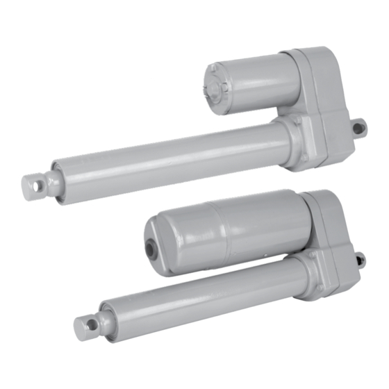
Electromechanical Actuators with Acme Screw CAUTION This manual contains important information for the correct installation, operation and maintenance of the equipment described herein.
Contents Section I General Information 1-1. General Information ........................3 1-2. Application Information ......................3 1-3. Inspection ...........................3 Figure 3-1. Dimensions in Inches .........................3 1-4. Warranty and Warranty Repair ....................3 Table 1-1. TA500 Performance at Rated Load ....................4 Table 1-2. TA1000 Performance at Rated Load ..................4 Section II Installation 2-1.
Duff-Norton’s satisfaction to have been 1-2. Application Information defective in material or workmanship. Claims must be made within one year after date of shipment. Duff-Norton The actuators described in this manual are intended for will not repair or replace any parts that become inopera-...
2-2. Motor Capacitor Black All AC units use permanent split capacitor motors requir- Retract ing an external motor run capacitor. Capacitor ratings are listed below. Extend Voltage Rating Duff-Norton No. White 115VAC 50uf,370VAC SK6405-7-15 Figure 2-1. Wiring Schematic 230VAC 15uf,440VAC SK6405-7-14 Connect AC neutral to ‘Common’...
1. Actuator limit switches must be set prior to potenti- lays or by utilizing a momentary action, Double Pole, ometer installation. Double Throw, Center-off toggle switch (Duff-Norton part 2. The potentiometer is 5000 ohm single turn. Resis- EM534). If actuator runs opposite the desired direction, tance changes approximately 235 ohms per inch for reverse the red and black motor wires.
Section III Operation Precautions 3-1. Motor ises is an indication that pins need lubrication to prevent pin wear. The motor used on this actuator has a very high power output for its size. Consequently, heat generation in the 3-3. Jamming motor is more rapid than in more conventional motors.
Section IV Maintenance 4-1. Lubrication 4-3. Load Bearing The load bearing and the screw and translating tube The bearing is permanently lubricated and not readily are adequately lubricated for the life of the unit. Gear- relubricated. A bearing which shows any sign of rough- ing receives a light brush coat of grease at the factory.
Page 8
Section V Illustrated Parts List Table 5-1. Linear Actuator Parts List Index Qty. Part Name Part Number Number Req. Gear housing EM1050-2 Shaft, cluster gear SK3410-43 Pinion SK3410-7 Screw, 10-32 x 3/4 H2695PC Housing plate EM1050-1 O-ring, -142 X6477-137 Motor, 115 VAC EM1050-24 Motor, 220-230 VAC EM1050-25...
Page 9
Use only replacement parts supplied by or approved by Duff-Norton. Non-authorized parts may be inadequate, resulting in serious injury or death in event of failure. Figure 5-1. Linear Actuator Exploded Illustration...
Page 10
Table 5-1. Limit Switch Parts List Index Part Name Qty. Req. Part Number Number Gasket EM1050-65 Limit switch base EM1050-72 Grooved pin, 1/16" S57-10C Cluster gear SK3275-20 Standoff EM1050-59 Gasket, cover EM1050-66 Cam, upper SK3275-21 Plate, terminal block EM1050-61 Screw, #6 x 1.5 H2706PC Terminal block EM1050-60...
Page 11
Use only replacement parts supplied by or approved by Duff-Norton. Non-authorized parts may be inadequate, resulting in serious injury or death in event of failure. Figure 5-2. Limit Switch Exploded Illustration...
Need help?
Do you have a question about the TAC Series and is the answer not in the manual?
Questions and answers