Advertisement
Quick Links
Instruction Manual
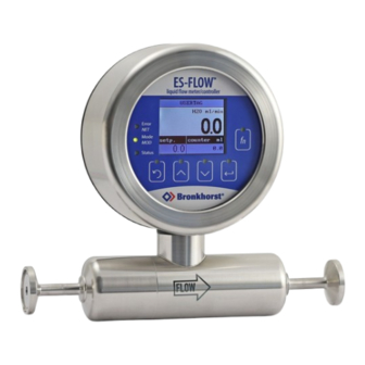
ES-FLOW® 1xxI
Ultrasonic Liquid Flow Meter/Controller
Doc. no.: 9.17.145 rev. K Date: 24-09-2024
ATTENTION
Please read this document carefully before installing and operating the product.
Not following the guidelines could result in personal injury and/or damage to the equipment.
Keep this document for future reference.
Advertisement

Subscribe to Our Youtube Channel
Related Manuals for BRONKHORST ES-FLOW 1 I Series


Summary of Contents for BRONKHORST ES-FLOW 1 I Series
- Page 1 Instruction Manual ES-FLOW® 1xxI Ultrasonic Liquid Flow Meter/Controller Doc. no.: 9.17.145 rev. K Date: 24-09-2024 ATTENTION Please read this document carefully before installing and operating the product. Not following the guidelines could result in personal injury and/or damage to the equipment. Keep this document for future reference.
-
Page 2: Symbols In This Document
Bronkhorst representative. · If the product is damaged, it should not be put into service. In that case, contact your Bronkhorst representative for service. · Check the packing list to ensure that you received all items included in the scope of delivery. -
Page 3: Warranty
Selected parts should be obtained only through Bronkhorst, to maintain accuracy and functionality of the product. If you are unsure about the suitability of a replacement component, contact your Bronkhorst representative for information. - Page 4 Bronkhorst® Instruction Manual ES-FLOW® 1xxI 9.17.145K...
-
Page 5: Table Of Contents
Bronkhorst® Table of contents Introduction ..................... . . 7 Scope of this manual . - Page 6 Bronkhorst® 3.3.6 Multifunctional switch ......................32 3.3.6.1...
-
Page 7: Introduction
Bronkhorst High-Tech B.V. cannot be held liable for any damage and/or injury resulting from unintended, improper or unsafe use, or use with other media and/or under other process conditions than specified at ordering time. -
Page 8: Product Description
Bronkhorst® Product description The ES-FLOW® 1xxI is a precise and compact volume flow meter with control function for liquids, based on a novel ultrasonic technology. Measuring principle Measuring is done in a straight tube, without obstructions or dead spaces. Multiple transducers measure both the surface acoustic wave and the transit time through the media. - Page 9 Bronkhorst® The documentation listed in the following table can be downloaded from www.bronkhorst.com/downloads Type Document Document no. Manuals Manual CANopen interface 9.17.131 Manual DeviceNet™ interface 9.17.026 Manual EtherCAT interface 9.17.063 Manual EtherNet/IP interface 9.17.132 Manual FLOW-BUS interface 9.17.024 Manual Modbus ASCII/RTU/TCP interface 9.17.035...
-
Page 10: Model Key
Bronkhorst® Model key The model key on the serial number label contains information about the technical properties of the product as ordered. The actual properties of your instrument can be retrieved from the diagram below. Instruction Manual ES-FLOW® 1xxI 9.17.145K... -
Page 11: Customized I/O Options
Bronkhorst® 1.6.1 Customized I/O options ES-FLOW® 1xxI instruments offer various customized input/output functions through pin 5 of the power connector and through pin 2 of the actuator output connector as an option. I/O options are factory installed as specified at ordering time, and cannot be changed manually. - Page 12 (controller enabled, see model key). · If the controller is enabled, the M8 connector can always be used to control a Bronkhorst® valve (through pin 3). · Although it is theoretically possible to have 3 controller options installed, no more than 1 signal should be used at any time.
-
Page 13: Installation
· Input and output signal Bronkhorst® instruments are pressure tested to 1.5 times the requested pressure rating and outboard leak tested to at least 2 * 10 mbar l/s Helium. The tested pressure is specified on the serial number label. If the serial number label is missing or if the specified pressure is insufficient, the instrument must not be used and should be returned to the factory. -
Page 14: Orientation
On models starting from MkII, the flow direction and display orientation can be adjusted at the factory, for which the instrument has to be returned. Contact your Bronkhorst representative for more information and arrangements. 2.2.3 Hygienic applications In order to comply with the 3-A Sanitary Standards, the ES-FLOW®... -
Page 15: Electrical Connections
Route cables as closely as possible alongside metal structures or components. · Ensure all electrical components are grounded to earth. When in doubt about the shielding of your cabling and/or electrical connections, contact your Bronkhorst representative. Communication interface Check if the default network settings match the configuration of the fieldbus system (if applicable). If necessary, the default... -
Page 16: Operation
First use Bronkhorst does the utmost to ensure that you receive a clean product.This does not, however, relieve the end user of the responsibility to ensure that the instrument and the system in which it is incorporated meet (hygiene) requirements that apply to the intended use of the instrument. -
Page 17: Main Screen Functions
Bronkhorst® The communication status of the instrument can be monitored with the three LEDs to the left of the screen. See LED indications for a description of the possible indications. A multifunctional switch ( ) to the right of the screen can be used... -
Page 18: Editing Setpoint
Bronkhorst® 3.3.1.4 Editing setpoint · The setpoint of a controlling instrument can be changed if the parameter is displayed in the custom readout area. · Instruments without a control function have no editable setpoint and can only be monitored (Custom readout 1 not available). -
Page 19: Resetting Alarm
Bronkhorst® 3.3.1.6 Resetting alarm Before resetting the alarm, be sure to eliminate the cause. Resetting the alarm without changing the conditions that caused it will re-activate the alarm immediately. When an alarm occurs, a message blinks in the top line of the main screen. If the alarm is configured to be reset automatically, the blinking stops as soon as the alarm conditions no longer apply. -
Page 20: Password Protection
Bronkhorst® Navigation · Inside menus and sub menus, the selected item is highlighted in red · Press to navigate to the required menu item · Arrows pointing up and/or down in the top line indicate the menu contains more items than can be displayed. -
Page 21: Editing List Selection
Bronkhorst® 3.3.2.3 Editing list selection 1. Select the parameter to 2. Press to enter edit 3. Press to scroll 4. Press to confirm the be edited: mode (the selected through the available selected option and value is highlighted): options: leave edit mode (the highlight is removed): 3.3.3... -
Page 22: Controller
Bronkhorst® In the Readout sub menu, the following parameters can be edited: Parameter Description Supported values · Readout format Display format of measured value in main screen actual · percentage · Type* Measurement type volume Note: value 'mass' can only be selected if parameter Density >... -
Page 23: Counter/Totalizer
Counter/totalizer Bronkhorst® flow meters have a built-in counter function, which can be used to monitor and/or control the amount of media flowing through the instrument. The flow can be stopped or changed when a certain limit is reached. Until the counter is reset, the counter setpoint overrides the regular setpoint. - Page 24 Bronkhorst® The Counter sub menu provides the following parameters and functions: Parameter Description Supported values · Counter mode Selected counter mode · up to limit · · Counter reset Reset method automatic · manual · Type* Measurement type volume ·...
-
Page 25: Alarm
Bronkhorst® 3.3.3.4 Alarm In the Alarm sub menu, the following parameters can be edited: Parameter Description Supported values · Mode Alarm type · min/max · response · power-up · Reset Reset method; reset alarm automatically if alarm conditions no automatic longer apply, or manually via the user interface ·... -
Page 26: Setup
Bronkhorst® 3.3.3.5 Setup Instruction Manual ES-FLOW® 1xxI 9.17.145K... -
Page 27: Advanced
Bronkhorst® The following parameters are available in the Setup sub menu: Parameter Description Supported values Usertag Custom instrument name text (16 positions) Serial Instrument serial number n/a (read only) Model Instrument model number n/a (read only) Firmware version Firmware version n/a (read only) ·... -
Page 28: Security Menu
Bronkhorst® 3.3.4 Security menu In the Security menu, access to some delicate items can be restricted. The password that is used for password protected items can also be changed here. The following items can be restricted: Item Description Factory setting... -
Page 29: Changing Password
If the password is lost (after changing it), it can be reset by entering an encrypted key. This reset key can be obtained by sending a so-called 'bht key' to your Bronkhorst representative. After entering the reset key, the password will be reset to the default value ('abc'). -
Page 30: Led Indications
Bronkhorst® 3.3.5 LED indications (green) Mode/MOD: operation mode indication (red) Error/NET: error/warning messages The tables below list the different LED indications: Green Pattern Time Indication continuous Power-off or program not running continuous Normal operation mode short flash 0.1 sec on,... -
Page 31: Interface Status
Bronkhorst® 3.3.5.1 Interface status On instruments with an Ethernet based fieldbus interface, a third LED (bi-color; green and red) indicates the status of the communication interface: Pattern Time EtherCAT® PROFINET continuous Power off or initializing Interface not (yet) started continuous... -
Page 32: Multifunctional Switch
Bronkhorst® Module status Pattern Time Indication continuous No power continuous Normal operation mode on, green 0.5 sec on, Device is in standby mode or configuration is missing, incomplete or incorrect blinking, 0.5 sec off green alternating 0.5 sec green, Self test mode 0.5 sec red... -
Page 33: Network Settings - Readout/Change
Bronkhorst® Changing control mode · By briefly pressing the switch 4 times with intervals of up to 1 second in normal operation mode, the instrument enters a state in which the control mode can be changed. · This is done in 2 steps, each represented by a LED indication pattern (green or red; see table below). -
Page 34: Changing Network Settings
Bronkhorst® The number of flashes for the baud rate indication is associated with the following baud rates: Number of Baud rate flashes FLOW-BUS Modbus PROFIBUS DP CANopen DeviceNet™ Ethernet based (index) (ASCII/RTU) automatically detected 187500 9600 9600 1000000 125000 100000000... -
Page 35: Disabling Multifunctional Switch
Each communication protocol uses its own methods for communicating with instruments and accessing parameters. FLOW-BUS Digital Bronkhorst® instruments can be monitored and operated using the free FlowWare software tools for Windows. These tools provide a graphical interface to the ProPar protocol (used by FLOW-BUS), for monitoring and editing parameter values. -
Page 36: General
Language). The GSDML file contains all necessary information, in XML format, to operate the device in a PROFINET system, including communication and network configuration, and all available operating parameters with their data types. A GSDML file for Bronkhorst® instruments can be downloaded from the product pages on the Bronkhorst website (search for 'gsdml profinet'). -
Page 37: Measurement And Control
Modbus address blocks are two bytes long. Larger data types use up to 8 subsequent address blocks, resulting in a maximum variable length of 16 bytes. Values longer than the maximum length are truncated. For more detailed information about setting up a Modbus network with Bronkhorst® instruments, consult the Modbus manual (see Documentation). -
Page 38: Analog Input
This parameter represents the controller output signal for control valve operation. 3.4.3 Alarms Alarm settings are most easily accessible using Bronkhorst FlowSuite, FlowPlot or FlowView or a Bronkhorst® readout and control unit. The built-in alarm functionality can be used to handle different alarm types: ·... - Page 39 Bronkhorst® Alarm Mode Type Access Range FlowDDE FLOW-BUS Modbus Unsigned char 0…3 97/3 0x0C23/3108 Available modes: Value Description Alarm off Alarm on absolute limits Alarm on limits related to setpoint (response alarm) Alarm at power-up(e.g. after power-down) (On DeviceNet™ instruments, only modes 0 and 1 are available)
-
Page 40: Counter And Totalizer
3.4.4 Counter and totalizer · Counter settings are most easily accessible using Bronkhorst FlowSuite, FlowPlot or FlowView or a Bronkhorst® readout and control unit. · When the instrument is powered down, it remembers the state of the counter. If the counter is active when the instrument is powered down, it is activated when powered up and then continues to count from the value at the time of power down. - Page 41 Bronkhorst® Counter Unit Type Access Range FlowDDE FLOW-BUS Modbus Unsigned char[4] see table 104/7 0xE838…0xE839/59449…59450 below This parameter contains the name of the counter readout unit. Counter Unit supports the following values: Mass Normal volume Standard volume Custom volume (1.01325 bar(a), 0 °C) (1.01325 bar(a), 20 °C)
-
Page 42: Network Configuration
Bronkhorst® Reset Counter Enable Type Access Range FlowDDE FLOW-BUS Modbus Unsigned char 0…15 104/9 0x0D09/3338 Available reset methods. The value is a bitwise summation of the enabled reset methods; convert the value to binary to see which methods are enabled. -
Page 43: Fluid
Bronkhorst® Communication via fieldbus connector (RS-485) Use the following parameters to configure the instrument for communication through the fieldbus connector (5-pin M12): Fieldbus1 Address Type Access Range FlowDDE FLOW-BUS Modbus Unsigned char 0…255 125/10 0x0FAA/4011 Fieldbus1 Baud Rate Type Access... -
Page 44: Controller
This parameter returns the traveling speed of sound in meters per second through the metered fluid, measured by the instrument. 3.4.7 Controller The picture below is a simplified visualization of the PID controller algorithm (proportional, integral, derivative) used by digital Bronkhorst® instruments. Instruction Manual ES-FLOW® 1xxI 9.17.145K... - Page 45 Bronkhorst® The controller speed controls the overall performance of the controller algorithm. Basically, to adjust the controller response, only the controller speed needs to be changed. The algorithm is based upon the difference between the setpoint and the measured value (called the error value). The correction signal to eliminate the error is assembled from 3 components (giving the algorithm its name): ·...
-
Page 46: Master/Slave Configuration (Flow-Bus)
Bronkhorst® Normal Step Response Type Access Range FlowDDE FLOW-BUS Modbus Unsigned char 0…255 114/5 0x0E45/3654 Response factor, applied to proportional action during normal control (at setpoint step). · Default value: 128 (no correction) · (response Other values adjust the controller gain (correction signal) as follows: Controller gain = Controller Speed * PID-Kp * 1.05... -
Page 47: Device Identification
Instrument serial number for identification. BHT Model Number Type Access Range FlowDDE FLOW-BUS Modbus Unsigned char[35] 113/2 0xF110…0xF117/ 61713…61720 This parameter shows the Bronkhorst® instrument model type information. Firmware Version Type Access Range FlowDDE FLOW-BUS Modbus Unsigned char[6] 113/5 0xF128…0xF12A/ 61737…61739... -
Page 48: 3.4.10 Special Parameters
Bronkhorst® 3.4.10 Special parameters Init Reset Type Access Range FlowDDE FLOW-BUS Modbus Unsigned char 82/64 0/10 0x000A/11 Init Reset is used to unlock secured parameters (marked with a symbol) for writing. It supports the following values: Value Description unlocked, secured parameters can be read and written to locked, secured parameters are read-only At power-up, Init Reset is always set to ‘Locked’... -
Page 49: 3.4.10.1 Default Control Mode
Adjusting zero point Zero-stability The zero point of a Bronkhorst® flow meter/controller (the measurement signal that indicates the absence of a flow) is factory adjusted with water at approximately 20 °C and atmospheric pressure (ambient conditions), with the instrument positioned upright. -
Page 50: Autozero Function
Bronkhorst® Prerequisites Zeroing an instrument requires that: · the ambient conditions (temperature, pressure) match those of the operating environment of the instrument. · the instrument is filled homogeneously and pressurized with the operational media, according to the typical process conditions. -
Page 51: Digital Procedure
3.5.3 Digital procedure Bronkhorst FlowSuite and FlowPlot provide an easy way to adjust the zero point of an instrument using RS-232 communication; the Autozero function automatically performs the procedure described here. To adjust the zero point using digital communication, set parameter values in the following sequence (see section... -
Page 52: Maintenance
Inexpertly servicing instruments can lead to serious personal injury and/or damage to the instrument or the system it is used in. Servicing must therefore be performed by trained and qualified personnel. Contact your Bronkhorst representative for information about cleaning and calibration. Bronkhorst has trained staff available. -
Page 53: Troubleshooting And Service
To track down problems in the fluid system, depressurize the fluid system and disconnect the suspected unit from the process line. Dirt or clogging might be quickly detected by visual inspection of disassembled fluid connections. If you suspect leakage, do not disassemble the device for inspection, but contact your Bronkhorst representative for service or repairs. - Page 54 Check the system for leakage. Follow vendor instructions when installing third party components (e.g. adapters, tubing, valves) Continuous maximum measured Inlet pressure too high Check inlet pressure value or output signal Sensor failure Contact your Bronkhorst representative Instruction Manual ES-FLOW® 1xxI 9.17.145K...
-
Page 55: Service
If you have a question about a product or if you find the product does not meet the specifications as ordered, do not hesitate to contact your Bronkhorst representative. To enable us to help you quickly and effectively, make sure to have the serial number (SN) ready whenever seeking contact with your Bronkhorst representative about a specific item. -
Page 56: Removal And Return Instructions
Follow the on-screen instructions to return the product. Disposal (end of lifetime) If you are a customer within the European Union and wish to dispose of Bronkhorst® equipment bearing the symbol of a crossed out waste disposal bin, you can return it in accordance with the removal and return instructions. -
Page 57: Parameter Index
Bronkhorst® Fmeasure Parameter index Fsetpoint Measure Parameters Setpoint Parameters - Alarms Setpoint Slope Alarm Delay Time Temperature Alarm Info Valve Output Alarm Maximum Limit Parameters - Network configuration Alarm Minimum Limit Fieldbus1 Address Alarm Mode Fieldbus1 Baud Rate Alarm New Setpoint... - Page 58 Bronkhorst® Instruction Manual ES-FLOW® 1xxI 9.17.145K...
- Page 59 Bronkhorst® 9.17.145K Instruction Manual ES-FLOW® 1xxI...
- Page 60 Service Contact Downloads Bronkhorst High-Tech B.V. +31 573 45 88 00 Nijverheidsstraat 1a info@bronkhorst.com NL-7261 AK Ruurlo, The Netherlands www.bronkhorst.com...
Need help?
Do you have a question about the ES-FLOW 1 I Series and is the answer not in the manual?
Questions and answers