Table of Contents
Advertisement
Quick Links
Advertisement
Table of Contents

Related Manuals for TRENDnet TV-IP602WN


Summary of Contents for TRENDnet TV-IP602WN
-
Page 2: Table Of Contents
CONTENTS About This User’s Guide .......................... i v Before You Start ............................. i v Packing List .............................. i v System Requirements ............................. v Default Settings .............................. v i INTRODUCTION .......................... 7 Features and Benefits .............................7 Camera Hardware Components ........................ 8 Front Panel Components ..........................8 LED Indicators ..............................8 Rear Panel Components ..........................9 INSTALLING THE CAMERA...................... 11 Attach Camera to Stand .......................... 11 Connect Ethernet Cable .......................... 12 Connect Power using AC Adapter and Power on Camera ................ 12 Reset Camera ... - Page 3 Load Saved Video Files .......................... 71 Play Video Files ............................ 72 ffdshow ................................ 73 TECHNICAL SPECIFICATIONS ....................... 79 ...
-
Page 4: About This User's Guide
TV‐IP602WN ProView Wireless N Pan/Tilt Internet Camera About This User’s Guide This User Guide provides instructions on how to install the TV‐IP602WN ProView Wireless N Pan/Tilt Internet Camera and use it for camera monitoring applications. Camera monitor applications are accessible through an Ethernet or 802.11b/g/n wireless local area network. Before You Start Please read and make sure you understand all the prerequisites for proper installation of your new wireless Network Camera. Have all the necessary information and equipment on hand before beginning the installation. Packing List Open the shipping carton and carefully remove all items. In addition to this Manual, ascertain that you have: • One TV‐IP602WN ProView Wireless N Pan/Tilt Internet Camera • Two Detachable Antenna • One Power Adapter(12V DC, 1.5A) • One Network Cable • One CD‐ROM (Utility & User’s Guide) • One Multi‐Language Quick Installation Guide • One Metal Mounting Plate • 2x M3 6mm Screws for screwing the Camera to the Metal Plate • 2x M3 16mm Screws for mounting the Camera to a wall or ceiling If any of the above items are missing, please contact your reseller. CAUTION: If powering up the camera with DC power, the Camera must be used with the power adapter included with the device. iv ... -
Page 5: System Requirements
TV‐IP602WN ProView Wireless N Pan/Tilt Internet Camera System Requirements Computer • CPU: P4 2.8GHz or above • Memory: 1G or above (4GB recommended if monitoring more than one camera) • VGA Resolution: 1024 x 768 or above (Independent Display Card recommended) • Network Card o For cabled connections: 10BASE‐T Ethernet or 100BASE‐TX Fast Ethernet Network Interface Card o For wireless connections: 802.11b/g/n series Wireless Interface Card • CD‐ROM Drive for Setup Wizard on Installation CD‐ROM • IPView Pro 2.0 Application Users must use Microsoft® Windows® XP, Vista, and 7 Operating System with: o Internet Explorer 7.0 or above o Mozilla Firefox 3.5 or above with Java Applet requires JVM (J2SE 1.5 or later, or JRE (J2SE) 6.0 or later). o Apple Safari 4.0 or above with Java Applet requires JVM (J2SE 1.5 or later, or JRE (J2SE) 6.0 or later). Note: When you connect multiple cameras and monitor their images synchronously, it is recommended to use a high performance system, such as a Pentium 4 2.8GHz PC. Network • Local Area Network: 100Base‐TX Fast Ethernet • Wireless Local Area Network: IEEE 802.11b/g/n Wireless LAN ... -
Page 6: Default Settings
TV‐IP602WN ProView Wireless N Pan/Tilt Internet Camera Default Settings Use the default settings to access the web‐based management software and live video display. Default configuration settings Username This is the Username you will be prompted to enter when you access the TV‐IP602WN configuration screens using a Web browser. The default Username is admin. Password This is the Password you will be prompted to enter when you access the configuration windows using a Web browser. The default Password is admin. IP address This is the IP address you will enter into the Address field of your Web browser to access the camera monitor screen and configuration menus using a Web Browser. The camera uses DHCP for IP settings by default. If a DHCP server is not detected, the default IP address is 192.168.10.30. (Make sure your computer is configured to belong to the 192.168.10.X subnet if using the default IP address of the camera.) Subnet Mask The default subnet mask is 255.255.255.0. vi ... -
Page 7: Introduction
TV‐IP602WN ProView Wireless N Pan/Tilt Internet Camera 1 Introduction The TV‐IP602WN ProView Wireless N Pan/Tilt Internet Camera is a standalone system that can be connected directly to an Ethernet or Fast Ethernet connection. The TV‐IP602WN also supports wireless transmissions based on the IEEE 802.11b/g/n standard. Compared to a conventional PC camera, the Pan/Tilt Internet Wireless Camera features a built‐in CPU and web‐based solution that can provide a cost‐... -
Page 8: Camera Hardware Components
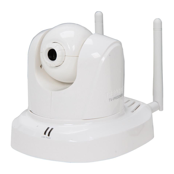
TV‐IP602WN ProView Wireless N Pan/Tilt Internet Camera Camera Hardware Components Below is a summary description of the camera hardware: Front Panel Components Adjustable focus camera lens Audio mic Link LED Power LED indicator indicator Front panel of TV‐IP602WN LED Indicators This LED indicator lights steady orange when a valid Ethernet link is established. It blinks orange when the video data is received or transmitted through the Ethernet link. LNK This LED also indicates the WPS status. The LED lights green when the Camera has made a successful WPS connection. The LED will blink 0.5 times per second when a WPS connection is trying to be established. The LED will blink 0.1 times per second if the WPS connection has failed. This LED indicator lights green when the camera is powered on. It remains dark when powered PWR off. 8 ... -
Page 9: Rear Panel Components
TV‐IP602WN ProView Wireless N Pan/Tilt Internet Camera Rear Panel Components The power connection to the camera when fitted with the Infrared lens is split between the camera body and lens using the power connection adapter cable attached to the infrared lens. All other cables connect to the camera at the rear panel. Antennas Reset Button Power WPS Button Line Out Receptacle Ethernet Port Rear Panel view of TV‐IP602WN The threaded posts are used for attaching the antennas. Fasten the antennas securely to Antennas the posts. Use to reset device to factory default settings including IP address and administrator user Reset Button name and password. WPS Button Use to setup the Wi‐Fi Protected Setup (WPS) function. Connect to Ethernet LAN. The port is auto MDI‐II/MDI‐X and auto‐negotiation for port Ethernet Port speed. 9 ... - Page 10 TV‐IP602WN ProView Wireless N Pan/Tilt Internet Camera Power receptacle Connect power adapter shipped with the camera and plug into suitable power source. Line Out The audio line out receptacle is a mini‐plug audio connection for speakers. 10 ...
-
Page 11: Installing The Camera
TV‐IP602WN ProView Wireless N Pan/Tilt Internet Camera 2 Installing the Camera The camera is intended for indoor use. The camera, the power adapter and power source should be protected from water and moisture, excessive heat, direct sunlight and cold. Make sure the power adapter and its cord and the Ethernet cable are safely arranged so they do not create a tripping hazard and will not be disturbed by people or objects moving past. Attach Camera to Stand To attach the metal plate carry out the following: 1. Remove the two rubber pads under the base of the Camera. 2. Slide the metal plate onto the base of the Camera, making sure that the two holes on the base of the Camera align with the two screw holes on the base of the Camera. 3. Secure the metal plate to the base of the Camera with the two screws provided. 4. The Camera can now be mounted to the ceiling or a wall. See the diagram below for more information. 1. Install the Camera to the ceiling using the two ceiling screws ( ); Or, ... -
Page 12: Connect Ethernet Cable
TV‐IP602WN ProView Wireless N Pan/Tilt Internet Camera Connect Ethernet Cable To connect the camera to your network, connect a Category 5 or better Ethernet cable to the network cable connector located on the camera’s left side panel, and then attach it to the network. The Ethernet port will automatically detect and adjust to the speed (10 or 100 Mbps) and polarity (Auto‐MDIX) of the connection. Connect Power using AC Adapter and Power on Camera To provide power to the camera, connect the AC power adapter to the DC power input connector, also located on ... -
Page 13: Reset Camera
TV‐IP602WN ProView Wireless N Pan/Tilt Internet Camera Reset Camera A manual reset can be conducted by following the procedure below. The reset button is located on the rear panel of the camera. To reset the system settings to factory defaults, please follow these steps: 1. Leave the camera powered on, do not disconnect the power. 2. Use a paper clip or similar object to press the reset button and hold. The reset button is located on the rear panel of the device. See the Rear Panel Components picture above to locate the reset button. 3. Keep the button pressed about 10 seconds. 4. Release the button. The camera will then automatically reboot itself. Upon restarting the camera loads the factory default configuration settings. The default IP address 192.168.10.30 and subnet mask 255.255.255.0 will be applied ... -
Page 14: Setupwizard
TV‐IP602WN ProView Wireless N Pan/Tilt Internet Camera 3 SetupWizard This section describes the how to setup a camera using the SetupWizard. To install the SetupWizard on a system running Windows, launch the SetupWizard on the installation CD‐ROM and follow the setup instructions. Once the software is installed, the SetupWizard utility is ready for use. Installing the SetupWizard 1. Click the Setup Wizard button for the Auto‐ Run menu screen. The InstallShield Wizard will appear: Click Next to continue. 2. The next window asks you whether you want to accept the License Agreement or not. If you agree with the Licensing Agreement, click the I Agree radio button and the Next > button. If you don’t agree with the Licensing Agreement, click the I Do Not Agree radio button to exit the install wizard. 14 ... - Page 15 TV‐IP602WN ProView Wireless N Pan/Tilt Internet Camera 3. The following window appears asking you to choose the desired installation location. By default the destination location is C:\Program Files\TRENDnet\SetupWizard\. Click the Browse button to change the default installation location. Click Next to continue. 4. The following window appears informing you that the installation is ready to start: Click Next to start the installation. 5. The software will start to install. The following window appears, showing the progress of the installation: 15 ...
- Page 16 TV‐IP602WN ProView Wireless N Pan/Tilt Internet Camera 6. When installation is complete the following window appears to confirm that the SetupWizard has installed successfully: Click Close to exit the installation. After installing the SetupWizard, the application program for the Camera is automatically installed on your computer. Launching the SetupWizard To launch the SetupWizard, double click the SetupWizard shortcut on your desktop or click Start > Programs > TRENDnet > SetupWizard > SetupWizard. SetupWizard‐ Install Your Camera 16 ...
- Page 17 TV‐IP602WN ProView Wireless N Pan/Tilt Internet Camera Connect the camera to your LAN using the provided RJ45 cable. Connect the AC Power Adapter to the back of the camera and to a live power socket. Click Next to continue. SetupWizard‐ Select Your Camera The following screen appears showing the cameras that have been found on your network: Click the camera you want to configure. Click Next to continue. 17 ...
- Page 18 TV‐IP602WN ProView Wireless N Pan/Tilt Internet Camera SetupWizard‐ Authentication On the following screen type in the ID and Password that you will use to configuring the camera settings: Type a User ID in the ID field. Type the password of the User in the Password field. Click Next to continue. 18 ...
- Page 19 TV‐IP602WN ProView Wireless N Pan/Tilt Internet Camera SetupWizard‐ Other Settings The following window allows you to configure additional camera settings: Type a name to help you identify the camera in the Camera Name field. Set the camera date and time from the Camera Time drop‐down menus. To use the time settings from your computer, click the Copy Local Time button. Click Next when you have finished configuring the other settings. 19 ...
- Page 20 TV‐IP602WN ProView Wireless N Pan/Tilt Internet Camera SetupWizard‐ Change Password The following screen allows you to change the default admin password: Carry out the following if you want to change the admin password: Tick the Change Password checkbox Type in a New Password in the New Password field and confirm it in the Confirm Password field Click the Next button to proceed to the next Setup window If you don’t want to change the admin password, leave the checkbox un‐ticked and click Next. 20 ...
- Page 21 TV‐IP602WN ProView Wireless N Pan/Tilt Internet Camera SetupWizard‐ Select a Connection Option The following window allows you to specify the connection method used by your camera network. Click the radio button of the network environment your camera is connected to. The available options are: PPPoE DHCP Fixed IP 21 ...
- Page 22 TV‐IP602WN ProView Wireless N Pan/Tilt Internet Camera SetupWizard‐ Select a Connection Option‐ PPPoE If your connection method is PPPoE, click the PPPoE radio button and click Next: The following window appears: Type the User Name used to connect to your PPPoE connection in the User Name field. Type the Password of the PPPoE User Name in the Password field and confirm it in the Confirm Password field. Click Next to proceed to the next setup window. 22 ...
- Page 23 TV‐IP602WN ProView Wireless N Pan/Tilt Internet Camera SetupWizard‐ Select a Connection Option‐ DHCP If your connection method is DHCP, click the DHCP radio button and click Next: 23 ...
- Page 24 TV‐IP602WN ProView Wireless N Pan/Tilt Internet Camera SetupWizard‐ Select a Connection Option‐ Fixed IP If your connection method is Fixed IP, click the Fixed IP radio button: The following window appears: Type in the IP Address, Subnet Mask, Default Gateway, Primary DNS Server IP address and Secondary DNS Server IP Address in the appropriate fields. Click Next to proceed to the next setup window. 24 ...
- Page 25 TV‐IP602WN ProView Wireless N Pan/Tilt Internet Camera SetupWizard‐ Setup Wireless After choosing your connection method, the following window appears: Choose if you want to connect to your camera using the wireless connection or not by clicking the appropriate radio button. Click Next to continue. 25 ...
- Page 26 TV‐IP602WN ProView Wireless N Pan/Tilt Internet Camera SetupWizard‐ Setup Wireless If you selected the option to use a wireless connection to connect to your camera the following window appears: Choose the Access Point you want to connect the camera to from the Available AP drop‐down menu. If the Wireless LAN you want to connect to doesn’t appear in the Available AP list, click the Re‐Scan button to scan for additional Wireless LAN’s. Type the SSID of the WLAN you want to connect to in the SSID field. Choose the Wireless Mode of your WLAN from the Wireless Mode drop‐down menu. Choose the Channel of your WLAN from the Channel drop‐down menu. Choose the Authentication method of your WLAN from the Authentication drop‐down menu. Choose the Encryption method of your WLAN from the Encryption drop‐down menu. Type the Encryption Key used by your Wireless LAN in the Key field. When you have finished configuring the wireless settings, click Next to continue to the next setup window. 26 ...
- Page 27 TV‐IP602WN ProView Wireless N Pan/Tilt Internet Camera SetupWizard‐ Setting Up The Camera The following window appears, summarizing the network settings of your camera: When you have finished setting up the Camera click the Next button. To make any changes to your Camera settings, click the Previous button. SetupWizard‐ Camera Restart The following window appears, indicating that the camera is restarting: 27 ...
- Page 28 TV‐IP602WN ProView Wireless N Pan/Tilt Internet Camera SetupWizard‐ Linking Mode If you configured the wireless connection, the following window appears: Choose to use wired or wireless to connect to the camera. Click Next to continue. 28 ...
- Page 29 TV‐IP602WN ProView Wireless N Pan/Tilt Internet Camera SetupWizard‐ Disconnect Wired If choose to use wireless, the following window appears: Unplug the RJ‐45 cable, and click Next to continue. SetupWizard‐ Camera Restart The following window appears, indicating that the camera is restarting: 29 ...
- Page 30 TV‐IP602WN ProView Wireless N Pan/Tilt Internet Camera SetupWizard‐ Complete After the camera has restarted, the following window will appear: Click the hyper‐link to connect to the camera web interface. If you want to setup an additional camera, click the Setup Another Camera button. When you have finished, click the Exit button to close the SetupWizard. 30 ...
-
Page 31: Using The Camera Web Manager
TV‐IP602WN ProView Wireless N Pan/Tilt Internet Camera 4 Using the Camera Web Manager The camera is easy to use and manage. Use a normal web browser to access the camera’s live video display, as well as the configuration software. It is recommended to check and make sure the computer can access and use the camera before placing it in the location where it will be used, especially if it is mounted to a ceiling or other area that is difficult to physically access. For the initial setup, use the SetupWizard program located on the TV‐IP602WN CD‐ROM included with the camera. Use the IPCam Wizard to assign an IP address and other network settings. Once the camera has an IP address, follow the instructions below to access the camera’s web management interface used to manage the camera and for video display. Mozilla Firefox to view the camera web manager, in order to have all NOTE: If using functions working properly, make sure VLC Mozilla plugin and Java JRE are both installed ... -
Page 32: Login
TV‐IP602WN ProView Wireless N Pan/Tilt Internet Camera To check proxy setting for Windows Internet Explorer: 1. In Windows, click the Start button, go to Settings and choose Control Panel. 2. In the Control Panel window, double‐click the Internet Options icon. (Alternatively you can access this Internet Options menu using the Tools pull‐down menu in Internet Explorer.) 3. Click the Connections tab and click the LAN Settings button. 4. Verify that the “Use proxy server” option is NOT checked. If it is checked, click in the checked box to deselect the option and click OK. Login To access the web manager directly from a computer or on a network without a DHCP server running, use the default IP address of the camera in the browser address entry to access the web manager. Type http://192.168.10.30 in the address bar and press Enter. The login dialog appears when accessing the camera. Type the default user name “admin”, default password “admin” and click the OK button to access the camera’s management interface. 32 ... -
Page 33: Web Manager And Live Video Display Page
TV‐IP602WN ProView Wireless N Pan/Tilt Internet Camera Web Manager and Live Video Display Page The live video display appears after successful logging in to the web manager. Camera video display in web manager 33 ... -
Page 34: Live Video Display User Interface
TV‐IP602WN ProView Wireless N Pan/Tilt Internet Camera Live Video Display User Interface When login the Camera, the Live View displays. Alternatively, you can click the Live View button on the screen to access the video images. The web manager’s live video page presents icons at the bottom used to change the display size, control snapshot and recording of video and audio controls. Links to other management menus are located at the top right porting of the interface. Click the SETUP link to view menus ... - Page 35 TV‐IP602WN ProView Wireless N Pan/Tilt Internet Camera Controlling the Camera You can control the Camera’s viewing angle using the control buttons on the left‐ hand side of the viewing window. You can control video modes, audio modes, recording settings and digital output using the control panel underneath the image (described on the next page). Outer Ring: Click the arrows on the outer ring to move the camara. Click the right arrow to move the camera to the right, the up arrow to move the camera up, etc. Home: Click the Home icon to move the camera to its home position. Patrol: Enables the Auto Patrol feature. Please refer to page 47 to configure preset locations. ...
- Page 36 TV‐IP602WN ProView Wireless N Pan/Tilt Internet Camera Audio Output control Audio speakers can be connected to the camera via the external audio miniplug. Use this control to enable or disable the audio output for voice or other audio through connected speakers. This is disabled by default. Event Indicators Motion Detection indicator The motion detection icon appears yellow when motion is detected in the zone previously configured for motion detection. Motion detection must be configured in the Motion Detection menu located in the Setup Menu directory. Recording indicator (right panel) This appears yellow while the video display is not functional properly. 36 ...
-
Page 37: Camera Configuration Setup
TV‐IP602WN ProView Wireless N Pan/Tilt Internet Camera Camera Configuration Setup After successfully logging in, the camera Live View screen will appear. Select Setup to enter into the configuration menu screen. Setup window 37 ... -
Page 38: Wizard
TV‐IP602WN ProView Wireless N Pan/Tilt Internet Camera Wizard The first menu to appear after clicking Setup is the the automatic setup wizard. You can use this wizard to configure settings for your camera’s Name, LAN and Internet, DDNS and Time/Date. Click Next to start the wizard otherwise select another menu choice from the left hand menu buttons. Setup Wizard Welcome window To configure the camera with the web manager’s SetupWizard, click the Next button and follow the instructions in the menus to configure network, time and name settings. To configure these settings without using the wizard, click the link for the settings to be configured to view the configuration menu. These menus are presented and described in the pages that follow. Step 1: Setup LAN Settings Select the DHCP Connection option if your wired or wireless connection will use a dynamically assigned IP address Select the Static IP Address option and then manual enter in the network settings your camera will use. Click Next to continue. 38 ... - Page 39 TV‐IP602WN ProView Wireless N Pan/Tilt Internet Camera Step 2: Setup Internet Settings To connect a camera directly to the Internet using a PPPOE connection, enter the username and password here. Your ISP should supply you with the credentials you need. You do not need to configure this setting if the camera is connected behind either a router or gateway. Click Next to continue. Step 3: Setup DDNS Settings To synchronize the public IP address of the Modem, when it has been modified, use the DDNS service settings. You must supply the Username and Password when utilizing the DDNS service. Server Address: Select your service providers Dynamic DNS web address. Host name: Enter the Domain name you were given from the DDNS service provider User name: Enter the account user name your DDNS service provider has given you. Password: Enter the password associated with the DDNS account user name. Verify Password: Repeat the password as entered above to verify it. Timeout: This setting is the notification period in hours when the camera sends a current global IP address update to the DDNS server configured above. The default is 576 hours. You can setup how often the camera notifies the DDNS server of its current global IP address. By default this is 576 hours. Click Next to continue. 39 ...
- Page 40 TV‐IP602WN ProView Wireless N Pan/Tilt Internet Camera Step 4: Camera Name Settings You can assign the camera a name here. Enter click Next to continue. the name and then Step 5: Setup Time Zone Use this step to configure the Time and Date, the Time Zone and the Daylight savings configuration of the camera. Time Zone: Select the Time Zone for your camera in the drop‐down list. Enable Daylight Saving: Select this to enable Daylight Savings for the Time Zone you have chosen above. This will automatically set daylight savings time depending on the date and time for each time zone. Keep current date and time: Select this choice to prevent any time and date changes from the current setting. Synchronize with NTP Server: Select this choice to enable NTP time slaved to the NTP server identified below. NTP Server: Enter the NTP server address or hostname Set date and time manually: Use this setting and the entry boxes below to enter the date and time desired as a manual configuration. Copy Your Computer’s Time Settings: Click this button to automatically set the time and date based on your computer’s settings. Click Next to continue. 40 ...
- Page 41 TV‐IP602WN ProView Wireless N Pan/Tilt Internet Camera Step 6: Setup Complete Carefully review your settings and then click Apply to finish the wizard. The camera will reboot to apply the new settings. 41 ...
-
Page 42: System
TV‐IP602WN ProView Wireless N Pan/Tilt Internet Camera System The System includes the Device Management and Time and Date menu. Device Management This menu can change the administator’s password, create user accounts and configure basic settings for the camera. Admin Password Setting Use this section to change the Admin Password for the camera. Type in a New Password and confirm it in the Retype Password field. Click Save to set the new password. Add User Account Use this section to add a new user. Up to 20 User accounts can be created on the TV‐ IP602WN camera. To create a new user, carry out the following: Type a name for the new user in the User Name field. Type in a new password in the New Password field. Confirm the password in the Retype Password field. Click Add to add the new user. The maximum number of users that can log onto the camera is 10 at the same time. Please keep in NOTE: mind the performance of the transmission speed will be reduced if multiple users have logged onto the camera simultaneously. User List Use this section to delete existing users. Users can be removed by selecting the name from the User Name drop‐down menu and clicking the Delete button. Device Setting Use this section to change the following Camera settings: Camera Name‐ This parameter sets the name of your camera. You can use this to type a name to help you identify the camera, e.g. Front Door could be used if your camera is focused on the front door of your house. 42 ... - Page 43 TV‐IP602WN ProView Wireless N Pan/Tilt Internet Camera Enable OSD‐ Check the checkbox to make the information bar On Screen Display (OSD) appear when viewing video. Label‐ If enabling OSD, type a name that will appear as the text label on the On Screen Display (OSD), e.g. Front Door could be used if your camera is focused on the front door of your house. Show time‐ If enabling OSD, tick this checkbox to display the time on the On Screen Display (OSD). LED Light‐ Click the Off radio button to turn the LEDs on the camera off even though the camera is in operation. Live View‐ Check the User Authentication check box to enable the authentication. Snapshot URL‐ Check the User Authentication check box to enable the authentication. Calibrate the Device Click the button to reset the camera to the home position and default settings after a serious of camera checks and movements. Use this in case the camera was moved manually by hand or otherwise. Time and Date Use the Time and Date menu to set the camera’s time settings manually, from the computer’s time or use a network time server (NTP server). Time Zone Use the drop‐down menu to select your time zone. Enable Daylight Saving If the region you are located in use Daylight Saving Time adjustments, tick this checkbox. Auto Daylight Saving If enabling Daylight Saving Time, click this radio button to adjust Daylight Saving Time automatically. Set date and time manually If enabling Daylight Saving Time carry out the following: Click this radio button to manually adjust Daylight Saving Time. Use the Offset drop‐down menu to set the Daylight Saving adjustment that will be used. Set the Start time and End time of the Daylight Saving period by using the drop‐down menus to set the Month, Week and Day of Week. Type the Hour and Minutes that the Daylight Saving adjustment will start and end in the respective fields. ...
-
Page 44: Network
TV‐IP602WN ProView Wireless N Pan/Tilt Internet Camera Network The Network includes the Network Setup, Wireless Set up and Dynamic DNS menu. Network Setup Click the Network Setup link to view menus for IP network settings, PPPoE configuration, DDNS and HTTP or RTSP port configuration. LAN IP Settings The camera’s IP settings can be configured as a DHCP client to obtain IP settings automatically, or configure static IP settings as needed for the private network. To use IP settings automatically obtained from a DHCP server on the network, select the DHCP Connection option. For manually entered or static IP settings, choose the Static IP Address option and type an IP Address unique on the LAN, appropriate Subnet Mask, Default Gateway address and Primary and Secondary DNS server IP address (for example, used for functions that require Internet access and DNS service such as SNTP with a named server). Click the OK button at the bottom of the web page to change and save the IP settings. UPnP If you want to enable the TV‐IP602WN Network Camera to connect to other UPnP devices in your network, tick the Enable UPnP checkbox. UPnP port forwarding To enable UPnP port forwarding, tick the Enable UPnP port forwarding checkbox. Enabling UPnP port forwarding allows the camera to add a port forwarding entry to be added to your router automatically. If your network uses different port numbers for External HTTP and External RTSP type in the values used by your network in the External HTTP port and External RSTP port fields. PPPoE For PPPoE client Internet access, tick the Enable PPPoE checkbox and enter the user name and password used for the PPPoE connection. Click the OK button at the bottom of the web page to apply the PPPoE account settings. Port Settings HTTP Port‐ Configure this with the HTTP Port to be used for viewing the camera over the Internet. RTSP Port‐ Configure this with the Real Time Streaming Protocol port used by an RTSP client to view the camera from for example, a mobile or smart phone. ... - Page 45 TV‐IP602WN ProView Wireless N Pan/Tilt Internet Camera RTSP User Authentication: Check this box to force the user to supply their credentials upon every camera access. Direct Video Stream Authentication Check the check box to enable the direct video stream authenticatin. Below are the direct view links. http://IP/directview/tvaview.cgi for Internet Explorer browser. http://IP/directview/tvjview.cgi for other browsers. Wireless Setup Enable Wireless Check this box to enable the wireless network connection mode of the camera Site Survey Click the pull‐down menu to see the list of wireless networks available. Click Rescan to update the SSID list. SSID The SSID (Service Set Identifier) is the name assigned to the wireless network. Type the SSID of the Wireless LAN you want to connect to in the SSID field or use the drop‐down menu to choose the SSID you want to connect the Camera to. Wireless Mode Click on the drop‐down menu to select either Infrastructure or adhoc wireless mode. Infrastructure allows direct connection to a wireless router or access point. Adhoc is for connecting with another wireless client that is in adhoc mode. Channel Use the drop‐down menu to choose the channel used for communicating with your Wireless LAN. A “channel” is a range of frequencies used to communicate between the Camera and an Access Point in Infrastructure mode, or the Camera and PC/Notebook in Ad‐Hoc mode. Authentication Use the drop‐down menu to select the wireless security authentication: Open, Shared, WPA‐PSK or WPA2‐ PSK. Encryption Use the drop‐down menu to select the encryption type based on the selected authentication method. Key Enter the exact security key (pass phrase) required for the authentication type. 45 ...
- Page 46 TV‐IP602WN ProView Wireless N Pan/Tilt Internet Camera Dynamic DNS If a Dynamic DNS account has been setup, use the DDNS menu to enter account information. Check the Enable DDNS check box and enter DDNS account information in the available entry fields. Click the OK button at the bottom of the web page to apply the DDNS configuration. 46 ...
-
Page 47: Video/Audio
TV‐IP602WN ProView Wireless N Pan/Tilt Internet Camera Video/Audio The Video/Audio includes the Video and Audio and Image Setup menu. Video and Audio Use this menu to configure up to four video profiles. These are used to optimize video encoding type, resolution, frame rate and bit rate settings on the camera for the type of display being used. Profile 4 is used to adjust settings for mobile display viewers (such as a mobile phone display). Night Mode Use Night Mode for use in low light situations. To enable Night Mode, tick the Enable Night Mode checkbox. Choose a value in seconds to specify how long the shutter will remain open after the camera flashes from the Shutter drop‐ down menu. This is useful in low light situations as it allows you to get more ambient light from the background, allowing you to see more detail from both the subject and background of your video/picture. Audio Setup Use the Audio Setup menu to enable and disable the microphone and speaker as well as adjust the volume of each. Click Ok to save the changes you have made to the Video and Audio settings. Click Cancel to discard any changes made. Image Setup Use the Image Setup configuration to optimize the live video display. 47 ... - Page 48 TV‐IP602WN ProView Wireless N Pan/Tilt Internet Camera Brightness Adjust the brightness level. The value range is from 0 – 100. (The default setting is 42.) Contrast Adjust the contrast level. The value range is from 0 – 100 increments of 20. (The default setting is 100.) White balance White balance is enabled (Auto) by default, if desired it can be disabled here. Flip Use this to flip the image upside down. This is used with the Mirror option if the camera is mounted in a hanging position as from a ceiling. Saturation Adjust the color saturation level. The value range is from 0 – 100 in increments of 20. (The default setting is 80.) Frequency Select the proper frequency (50Hz or 60Hz) to eliminate flicker or use the Auto select. B/W This option changes the display to a black and white only display (that is, no color is displayed in the video). Mirror Use this to produce a mirror image display. This is used with the Flip option if the camera is mounted in a hanging position, as from a ceiling. Reset to Default Click this button to reset the TV‐IP602WN Image Settings back to factory defaults. 48 ...
-
Page 49: Action
TV‐IP602WN ProView Wireless N Pan/Tilt Internet Camera Action The Action includes the Recording, Snapshot and Preset Position menu. Recording The Recording menu is used to determine when and how digital video recordings are handled. Recordings can be saved to a shared folder on a secure server. The recording can be scheduled or event based using motion detection as the trigger. One option allows resolution of recordings to be adjusted down to use less hard disk space. Recording can be stopped when the hard disk is full or choose the option to overwrite the disk to replace old recordings. Enable recording Tick this checkbox to enable the recording feature and save to a Samba drive on your network. Samba Auth Use the drop‐down menu to specify whether a user name and password is required to access the Samba drive. If no user name or password is required to access the Samba drive, choose Anonymous from the drop‐down menu. If a user name and password is required to access the Samba drive, choose the Account option from the drop‐down menu and configure the parameters as described below: User Name‐ Type the user name required to access the Samba drive. Password‐ Type the password required to access the Samba drive. Password Confirm‐ Type the password required to access the Samba drive for verification. Server‐ Type the name or IP address of the server your Samba drive is on. Shared Folder‐ Enter the path that points to the shared server. Click the Test button to check that the TV‐IP602WN can connect to the Samba drive. 49 ... - Page 50 TV‐IP602WN ProView Wireless N Pan/Tilt Internet Camera Samba Status‐ Check this item to see if the Samba drive is enabled. Click Get Status to check it. Recording Options Resolution‐ Select the profile from the drop‐down menu. Refer to the Audio and Video section for more information on profiles. Record until‐ Enter the minimum available hard drive space that must be left free and available for use when recording. When Storage is Full‐ Use the Stop recording setting to stop the recording when there is no longer any hard drive space. Otherwise use the Overwrite older recordings setting to record over old data when there is no longer any hard drive space. Scheduling Event Based‐ Check this setting to use event based triggering. Motion detection triggered recording‐ Check this option to start recording upon motion being detected. Prerecord Seconds‐ This settings causes the camera to buffer a certain amount of video set in this field to save when motion is detected. The maximum amount of pre‐detection video recorded is 15 seconds. Postrecord Seconds‐ Once event‐base triggered recording begins and the event (for example motion detection) has ceased it will continue recording for the amount of time set here. A maximum post‐ event recording time of 15 seconds is settable. Continuous‐ Selecting this option causes the camera to record video continuously. Only for use with Samba. Scheduled‐ Selecting this option allows you to manually schedule when the recordings with begin and end each day. Snapshot The Trigger menu is used to determine when and how recorded digital images from snapshots are handled. Use motion detection to trigger a snapshot and email it to the account configured here. Alternatively, the images can be sent to an FTP server. Configure FTP Server and email address information, and click to checkmark either or both options to use. 50 ...
- Page 51 TV‐IP602WN ProView Wireless N Pan/Tilt Internet Camera Scheduling Snapshot scheduling includes three options, snapshots can be: • Event Based Images are created based on triggering events (motion detection and digital input signal via I/O terminal). • Continuous (FTP only) Images are created at set intervals and sent to an FTP server. The intervals determine how often the snapshots are made and are configured in the FTP Server setup menu. • Scheduled (FTP only) Images are created based on a set schedule. Use the schedule provided to determine the time periods when images are configured and sent to an FTP server. This also requires an Interval setting to set the time period between snapshots. Send to Tick the E‐mail Address checkbox to specify that the images will be sent to an e‐mail address. Configure the parameters as described below: User Name‐ Type the User Name or login name for your e‐mail account. Password‐ Type the password for your e‐mail account. SMTP Mail Server‐ Type the SMTP server for your e‐mail account. Sender E‐mail Address‐ Type the e‐mail address that you want to appear as the “From:” e‐mail address in the snapshot e‐mail. Recipient E‐mail Address‐ Enter the e‐mail address that you want to send the snapshots to. Port‐ Enter the port number that will be used to send the snapshot e‐mails. Test‐ Click this button to send a test e‐mail from the TV‐IP602WN to the specified recipient e‐mail address to verify that all the credentials have been configured correctly. Tick the FTP Server checkbox to specify that the images will be sent to an FTP Server. Configure the parameters as described below: ...
- Page 52 TV‐IP602WN ProView Wireless N Pan/Tilt Internet Camera Filename Prefix‐ Enter the prefix you want to attach to your snapshot files. Port‐ Enter the port number used by your FTP server. Passive Mode‐ Tick this checkbox if your FTP server requires you to use passive mode. Click the Ok button to save your changes, or click Cancel to discard any changes made. Preset Position Presets allow you to program a home camera view and programmable positions and save them for future viewing and recording. Set as Home Click this button to set the Home postion to the current view. Default Home Click to set the home position of the camera view to the default factory programmed position. Pan Speed Use this drop‐down menu to configure the camera panning speed from 1 to 10 where 10 is the fastest panning speed. Tilt Speed Use this drop‐down menu to configure the camera tilt speed from 1 to 10 where 10 is the fastest tilt speed. Current Postion Type a name to use for the current camera view you would like to save as a preset position. Then click Add to save it. Preset Position Use the drop‐down menu to select the position that has been saved. Click Delete to remove it. Preset Locations This box shows the available Preset Locations saved which can be moved to the Selected Locations box below by highlighting them and clicking the Select button. Selected Locations The preset locations in this box: determine the locations the camera will view when the Patrol button is pressed in the Live View window. ...
-
Page 53: Motion Detection
TV‐IP602WN ProView Wireless N Pan/Tilt Internet Camera Motion Detection Motion detection is used to trigger video recording when motion is detected in a designated portion of the video display. To designate a portion of the display used for motion detection, choose the Draw motion area option and use the mouse and left mouse button to draw a rectangular area. The drawn area appears as a red box on the display in the Motion Detection menu. Tick the Enable Video Motion check box to check mark it and click the OK button. Sensitivity level can be set by typing a value from 0 – 100, with 100 being the most sensitive. To remove an established drawn motion area, select the Erase motion area option and click OK. To remove an area that has not yet been saved, click Clear. Tools The Tools includes the Backup and Resotre and Firmware Upgrade menu. Backup and Resotre Save To Local Hard Drive To save configuration settings for the camera to a file on a local hard disk, click the Save Configuration button. A prompt appears to confirm that you want to save the file. Choose the location and save the file to load the same settings. Load From Local Hard Drive To load a previously saved configuration settings file, click the Browse button to Load From Local Hard Drive to locate the file, and then click the Load Configuration button. It will take a few seconds to load the new settings. The camera will then restart. Restore To Factory Defaults To restore the camera to the factory default configuration settings, click the Restore Factory Defaults button. A prompt appears to confirm that you want to restore the default settings. Click OK to restore the ... -
Page 54: Device Info
TV‐IP602WN ProView Wireless N Pan/Tilt Internet Camera Reboot Device To perform a simple restart of the camera, click the Reboot Device button. Firmware Upgrade To upgrade the camera firmware, make sure the correct firmware file is located on your computer. Click the Browse button to locate the file. After locating the file, click the Upload button to load the file. It will take several seconds to load the firmware and restart the camera. Device Info The Action includes the Device Info, Log and Acknowledges menu. Device Info Network information, MAC address and firmware version is displayed in the Device Information display. Log Click the Log link to view the camera’s current log. To save the log in simple text form on your computer, click the Download button. Click Clear to delete all entries in the log. 54 ... - Page 55 TV‐IP602WN ProView Wireless N Pan/Tilt Internet Camera Acknowledges This menu displays all the achnoledgements of the camera. 55 ...
-
Page 56: Ipview Pro 2.0
TV‐IP602WN ProView Wireless N Pan/Tilt Internet Camera 5 IPView Pro 2.0 This section describes the how to setup a camera using the IPView Pro 2.0 camera monitoring software. To install IPView Pro 2.0 on a system running Windows, launch the IPView Pro 2.0 installation software on the installation CD‐ROM and follow the setup instructions. Once the software is installed, the IP Cam Center camera monitoring utility is ready for use. Add up to 32 network cameras to monitor using the software. Additional software, IPCam Player software is also installed. The IPCam Player is used for playing recorded video from cameras that have been configured to save recorded files. Launching IPView Pro 2.0 for the first time To launch IPView Pro 2.0, double click the IPView Pro shortcut on your desktop after installation or click Start > Programs > TRENDnet > IPView Pro 2.0 > IPView Pro 2.0. If this is the first time using the software, the menu that appears is the Add camera menu: 56 ... - Page 57 TV‐IP602WN ProView Wireless N Pan/Tilt Internet Camera Add a camera for monitoring The Add camera menu is presented the first time the IPView Pro 2.0 software is launched. This menu is used to add cameras to the user interface for monitoring. After the first time running the software, this menu can be accessed at anytime from the Configuration menus. The Configuration menus are described in a later section of this chapter. Notice that the IPView Pro 2.0 software has automatically detected eligible cameras running on the network. To add a camera to the IPCam user interface, follow these instructions: 1. Check the list of cameras detected by the software. If the camera you want to add does not appear on the list, click the Refresh button to conduct another search. Choose the camera to add Enter ID and password for the camera being added 2. Select the camera to add from the list, enter the administrator’s user name (ID:) and password, a preview of the live video display will appear. Click the OK, add this camera button, a confirmation message informs when the camera is connected and added to the IPView Pro 2.0 monitoring group. Repeat this procedure for all the cameras being added. Click the Exit button after all the cameras have been added. ...
- Page 58 TV‐IP602WN ProView Wireless N Pan/Tilt Internet Camera If the camera does not appear listed, click the Input the location of camera tab above the list to view a new menu. Enter the IP address or the URL (for example, ipcam.ddns.org) of the camera being added, type the user name and password and click the Preview to verify that a link can be established. The live video of the camera should appear in the Live preview display. If a link cannot be established, run the SetupWizard software for the camera and verify the correct IP address. Click Exit to return to the main Add camera menu. Type the IP address of the camera Enter user name and password for camera being added 3. Once the cameras have been added, they are ready to be used in the main IPView Pro 2.0 user interface. Close the Add camera menu (click Exit) to go to the main user interface. See below for a description. 58 ...
-
Page 59: Ipview Pro 2.0 User Interface
TV‐IP602WN ProView Wireless N Pan/Tilt Internet Camera IPView Pro 2.0 User Interface Below is a general description of the user interface. NO. Item Description Live video display area Display area for single or multiple cameras of live video. Right click any display area to 1 view a list of quick configure options for that camera including the “Replace camera content …” option used to change the order of the live video displays for multiple camera views. Minimize and Exit Use to minimize IPView Pro 2.0 interface or exit the program, a confirmation is required 2 to exit. Pan and Tilt control Click directional arrows to move camera in that direction within the limits of the pan and 3 (cameras using RS‐485 tilt range. The + in the center of the control is used to return to the home or center view Pan/Tilt device only) as configured for the camera. Snapshot, recording and See below for detailed information. 4 audio controls Live video display controls See below for detailed information. 5 Camera configuration menu See below for detailed information. 6 Camera status Use to quickly assess the status of operating cameras. Click box to select camera display. 7 The status indicators for each camera display recording, motion detection and GP input status. Camera information ... - Page 60 TV‐IP602WN ProView Wireless N Pan/Tilt Internet Camera Display Controls The primary display and IPView Pro 2.0 control icons are described in detail below. When there are more than one camera displays viewed, one of the displays can be selected for management or additional changes. Simply left click any display to select it. Notice the border around the display is bright aqua blue, indicating the “selected” status. For example, to go to a single screen display for any one camera, select the camera and click the single screen display. Left click any display to “select” that display for camera management. Right click to view camera management and display options. Snapshot, recording and audio controls The still photo camera icon is used to take a snapshot of the selected live video display. The video camera icon is used to begin video recording of the selected live video display. Snapshot and videos files are stored in a default folder on the administrator’s system, or in a folder designated by the administrator. The audio controls are represented by a microphone icon to activate the internal mic or the auxiliary audio input (if present), and a speaker icon for the audio output (remote speakers, if present). Notice that when these functions are activated, the color of the icon changes from white to yellow. Audio and video controls - inactive Audio and video controls - activated 60 ...
- Page 61 TV‐IP602WN ProView Wireless N Pan/Tilt Internet Camera Live video display controls Use the video display controls to change the view of the live video display. This is useful for multiple camera application. Click the arrows to manually cycle through the active camera’s live displays when using a single camera display screen. Click multi-screen display icons to change the number of camera’s displayed at one time. To change the order in which the camera displays appear in the interface, move the cursor over a display you want to change and right click.
-
Page 62: Camera Configuration With Ipview Pro 2.0
TV‐IP602WN ProView Wireless N Pan/Tilt Internet Camera Camera configuration with IPView Pro 2.0 Access the camera configuration menus by clicking on the gear icon at the bottom of the right hand panel of the IPView Pro 2.0 user interface. Configuration options include adding and deleting cameras from the display view, configuration of motion detection and digital input with schedules, recording options, email alerts and other network settings. Adding a Camera The procedure to add a camera after the initial launch of the software is very similar to the procedure used during the first setup. Follow the instructions below to add cameras. To add a camera: Click the Configuration icon to view the Camera Setup menu. The top most tab of the menu is the Camera Management tab. A list of active cameras appears on the left half of the menu. Select the camera to be added from the list. Click Add camera by IP/URL to find the specified IP address or network URL of the camera you want to add. 62 ... - Page 63 TV‐IP602WN ProView Wireless N Pan/Tilt Internet Camera Select the camera to add from the list, enter the administrator’s user name and password, a preview of the live video display will appear. Click the OK, add this camera button, a confirmation message informs when the camera is connected and added to the IPView Pro 2.0 monitoring group. Repeat this procedure for all the cameras being added. Click the Exit button after all the cameras have been added. The camera added now appears in the Camera List. To launch the web manager for the newly added camera or any camera in the active camera list, select it and click the Browse selected camera button. Removing a Camera To remove the camera from the list of active: Select the camera you want to remove. Click Delete selected camera. Any camera display can be removed from the main IPView Pro 2.0 user interface by NOTE: right‐clicking on the display screen for the camera and selecting the Remove this Camera option. 63 ...
-
Page 64: Schedule Recording With Ipview Pro 2.0
TV‐IP602WN ProView Wireless N Pan/Tilt Internet Camera Launch Web Manager for Selected Camera To launch the web‐based IP Camera manager for any active camera in the list, simply select it and click the Browse selected camera button. Schedule Recording with IPView Pro 2.0 Use the Configuration window to create schedules for recording and apply the schedules to any camera. Click the Monitoring Settings tab to view the Schedule recording menu (the first menu viewed in the Camera Settings menu tab). To apply an existing schedule template, tick Enable schedule recording, click the Select button and choose a schedule from the list of previously created schedule templates. If a new schedule is needed it can be created from the Select schedule Profiles window (See below). 64 ... - Page 65 TV‐IP602WN ProView Wireless N Pan/Tilt Internet Camera Create Schedule Profiles To make a new schedule profile, click the Edit Profiles button to view the Edit schedule profiles window. Use this menu to create new schedules for recording. 65 ...
-
Page 66: Setup Motion Detection And Digital Input With Ipview Pro 2.0
TV‐IP602WN ProView Wireless N Pan/Tilt Internet Camera Setup Motion Detection and Digital Input with IPView Pro 2.0 The Monitoring settings tab also includes Motion detection setup which has the schedule option to apply a schedule for the action taken or always take the specified action. Tick Enable motion detection check box to create the monitor area. Click the Setup motion detection button to see the Setup motion detection of the camera window. 66 ... - Page 67 TV‐IP602WN ProView Wireless N Pan/Tilt Internet Camera Enter the percentage of Sensitivity and Draw a motion detection area and click Save settings to enable the motion detection 67 ...
-
Page 68: Ipview Pro 2.0 Recording Options
TV‐IP602WN ProView Wireless N Pan/Tilt Internet Camera IPView Pro 2.0 Recording Options The Recording Options configured in the IPView Pro 2.0 help to conserve and manage allowed memory storage (disk space) and for video file management. Recorded files can be limited by time elapsed or by size. Use the select storage folder to choose an alternative destination for stored video files. Storage limits can be set for each camera by time elapsed or hard disk space allowed. A limit can also be placed for the system and all cameras used in IPView Pro 2.0. 68 ... -
Page 69: Ipview Pro 2.0 Other Options
TV‐IP602WN ProView Wireless N Pan/Tilt Internet Camera IPView Pro 2.0 Other Options The Other Options available for configuration include Proxy server setup, email notification, scan interval and alert type settings. 69 ... -
Page 70: Playing Video Files On A Computer
TV‐IP602WN ProView Wireless N Pan/Tilt Internet Camera 6 Playing Video Files on a Computer IPCamPlayer software is installed on the monitoring station or administrator’s system along with the IPView Pro 2.0 monitoring software. Use it to playback and manage recorded video from the cameras added to the IPView Pro 2.0 group. In order to use the software however, it is necessary to first install the ffdshow package of codecs used for media files. There is an ffdshow installation file on the CD shipped with the camera. Install ffdshow before using the IPCamPlayer. For information on installation and use of ffdshow, see the ffdshow section at the end of this chapter. Click to launch IPCamPlayer. The IPCamPlayer can be launched directly from the IPCamCenter or from the Programs menu. To launch the program from the IPView Pro 2.0 interface, click the movie icon on the control panel of the main IPView Pro 2.0 interface to launch IPCamPlayer. NOTE: Install the ffdshow package of video codecs from the installation CD before using the IPCamPlayer. 70 ... -
Page 71: Load Saved Video Files
TV‐IP602WN ProView Wireless N Pan/Tilt Internet Camera Load Saved Video Files Each camera has a file created automatically for storing video files. These files are normally located in the My Documents folder in Windows. The file folders are named according to the IP address and camera model. For example, 192.168.10.30_TV‐IP602WN is the name of the file folder for the TV‐IP602WN using the default (non‐DHCP) IP address. IPCamPlayer User Interface NO. Item Description File list Video files added to the list are viewed in the order listed. 1 View Screen Video files in the list are played here. The progress bar and starting time of the video 2 clip appears beneath the view screen. Add/Delete files from list Use the Search Files button to add recorded video files. A new menu pops up that is 3 used to find and add files to the list. (See description on next page) Playback controls Standard video playback controls for Stop, Play/Pause, go to next file (>>) or go to 4 previous file (<<) Faster and Slower to control speed of playback. Playback can be slowed to as much as 1/8 normal speed or speeded up to as fast as 8 times the normal speed. The vertical slider control is used for audio volume control. 71 ... -
Page 72: Play Video Files
TV‐IP602WN ProView Wireless N Pan/Tilt Internet Camera To view recorded video files in the IPCamPlayer, it is first necessary to locate and select the files to be viewed and add them to the list. Click the Search Files button in the IPCamPlayer main interface and a new menu appears. In the new menu, use the Select Camera pull‐down menu to choose the video file folder of the camera to be reviewed. Use the Search Time menu to narrow the search to a specific time and date. Finally, the Event selection menu is used to further narrow the scope of the file search for videos triggered by Motion Detection or a Digital Input device. When the search criteria have been defined, click the Search button to place qualified files in the Search list. Choose the files to be added to the view file list by check marking the individual files or click the Select All button to check mark all files in the Search list, click Add to place the check marked files on the list of files for viewing. After the files to be viewed have been chosen, click the OK button. Play Video Files Now that the recorded video files have been selected and placed on the file list, they can be played and reviewed in the IPCamPlayer. Use the standard playback controls to play video files at normal speed or slowed down, paused, speeded up etc. Use the mouse and left click to grab the playback sliding progress indicator to move back and forth through the video. 72 ... -
Page 73: Ffdshow
TV‐IP602WN ProView Wireless N Pan/Tilt Internet Camera ffdshow The ffdshow software is used for audio and video encoding and decoding, especially for MPEG‐4 formats. It is free software used on Windows systems and enables the user to tweak media playback and select specific codecs and formats. For use with the IPCamPlayer, the default settings used for ffdshow installation are all that is needed. Expert users can change audio and video codecs as desired with one of the three ffdshow configuration utilities installed along with the codecs. The configuration utilities can be accessed ... - Page 74 TV‐IP602WN ProView Wireless N Pan/Tilt Internet Camera 3. The InstallShield Wizard will appear, click Next in the welcome screen. 4. Accept the default location (Windows Programs folder) on the system for placement or Browse to choose an alternative, Click Next to continue. 5. Click to check the components that will be installed. For IPCamPlayer it is only necessary to use the default components already selected. Click Next to continue. 74 ...
- Page 75 TV‐IP602WN ProView Wireless N Pan/Tilt Internet Camera 6. Accept the default destination folder (ffdshow) or Browse to choose an alternative, Click Next to continue. 7. Click to check the additional tasks that will be installed. For IPCamPlayer it is only necessary to use the default formats already selected. Click Next to continue. 75 ...
- Page 76 TV‐IP602WN ProView Wireless N Pan/Tilt Internet Camera 8. Click to check the video applications that use ffdshow. For IPCamPlayer it is only necessary to use the default applications already selected. Click Next to continue. 9. Click to check the audio applications that use ffdshow. For IPCamPlayer it is only necessary to use the default applications already selected. Click Next to continue. 76 ...
- Page 77 TV‐IP602WN ProView Wireless N Pan/Tilt Internet Camera 10. Choose a speaker setup or choose Disable mixer if unsure. The audio function will work regardless of what speaker setup is chosen. Usually it will choose the default arrangement used on system on which it is being installed. Click Next to continue. 11. Review the information and click Install if satisfied that it is correct to install the necessary codecs. The installation will take a few seconds. 77 ...
- Page 78 TV‐IP602WN ProView Wireless N Pan/Tilt Internet Camera 12. If desired, any of the three configuration utilities included with the ffdshow installation can be launched by checking the appropriate box. Click Finish to complete the installation. To download the latest copy of ffdshow please check the ffdshow website NOTE: http://ffdshow.en.softonic.com/ 78 ...
-
Page 79: Technical Specifications
TV‐IP602WN ProView Wireless N Pan/Tilt Internet Camera A Technical Specifications Camera General Sensor: 1/4” CMOS Sensor Board Lens Focal Length: 4.57mm F/No: 1.9 Minimum illumination: 0.5 lux Focus Depth: 20 cm ~ infinity View: Horizontal: 45.7 degrees Vertical: 35.1 degrees Diagonal: 55.6 degrees Digital Zoom: 16x Audio Built‐in omni‐directional microphone Sensitivity: ‐42dB +/‐ 3dB (5 meters max.) Frequency: 50~16000Hz S/N: >58dB Codec: ARM/PCM External speaker output (speaker sold separately) Two‐way audio with echo canceling Pan & Tilt Pan: ‐156° ~ +156° Tilt: up 70°and down 45° Preset positions: 10 Image & Video Compression: simultaneous MPEG‐4 / MJPEG Profiles: up to 4 profiles simultaneously IRIS Control /white balance control: automatic Resolution: 640 x 480 (at 30 fps), 320 x 240, and 160 x 120 Hardware Network IEEE 802.3u 10/100Mbps Auto‐MDIX Fast Ethernet LED Power, Link/Act 79 ... - Page 80 TV‐IP602WN ProView Wireless N Pan/Tilt Internet Camera Reset Button Reset to factory default Power Consumption 10.1 Watts (max. @ motor on) 5.6 Watts (max. @ motor off) Power 12V, 1.5A external power adapter Dimension 112 x 130 x 110mm (4.4 x 5.1 x 4.3 in.) Weight 485g (1.1lb) Temperature Operating: 0°C ~ 45°C (32°F ~ 113°F) Storage: ‐15°C ~ 60°C (5°F ~ 140°F) Humidity Max. 85% (non‐condensing) Certifications CE, FCC Requirement Management Internet Explorer 7.0 and 8.0 Interaface To Run IPView Pro Windows 7 (32/64‐bit), Vista (32/64‐bit), XP (32/64‐bit) IPView Pro 2.0 Channel: supports up to 32 cameras Software Record/Playback/Motion Detection/Audio Network Protocols IPv4, ARP, TCP, UDP, ICMP DHCP Client, NTP Client, DNS Client, DDNS Client, SMTP Client, FTP Client HTTP Samba Client PPPoE UPnP RTP (Real Time Protocol) RTCP (Real Time Control Protocol) RTSP (Real Time Streaming Protocol) Wireless Standard ...
- Page 81 TV‐IP602WN ProView Wireless N Pan/Tilt Internet Camera Security 64/128‐bit WEP, WPA/WPA2‐PSK Output Power 802.11b: 18dBm (typical) 802.11g: 15dBm (typical) 802.11n: 13dBm (typical) Receiving Sensitivity 802.11b: ‐85dBm at 11Mbps 802.11g: ‐73dBm at 54Mbps 802.11n: ‐65dBm at 300Mbps Channels 1~11 (FCC), 1~13(ETSI) Management Accounts Up to 20 user accounts Remote Login Remote management supported Backup / Restore Save/retrieve configuration files Log System log up to 500 entries Settings Image Brightness, contrast, saturation, sharpness, white balance, flip, mirror (horizontal/vertical), black & white, day, night, schedule mode Video Setting Encoding type: MJPEG ‐ Resolution: 640 x 480, 320 x 240, 160 x 120 ‐ Frame rate: 1, 2, 3, 5, 10, 15, 30 ‐ JPEG quality: Low, Fair, Standard, Good, Excellent Encoding type: MPEG‐4 ‐ Resolution: 640 x 480, 320 x 240, 160 x 120 ‐ Frame rate: 1, 2, 3, 5, 10, 15, 30 ‐ Fixed bit rate: 64k, 128k, 256k, 384k, 512k, 768k, 1M, 1.5M, 2M ...
- Page 82 TV‐IP602WN ProView Wireless N Pan/Tilt Internet Camera Real time snapshot Port Settings HTTP port: 80 (default) RTSP port: 554 (default) Dynamic DNS Yes Support Time Synchronize with NTP server or set time / date manually 82 ...
- Page 83 Return Material Authorization (RMA) number will be issued. An RMA number is required in order to initiate warranty service support for all TRENDnet products. Products that are sent to TRENDnet for RMA service must have the RMA number marked on the outside of return packages and sent to TRENDnet prepaid, insured and packaged appropriately for safe shipment. Customers shipping from outside of the USA and Canada are responsible for return shipping fees. Customers shipping from outside of the USA are ...
- Page 84 TV‐IP602WN ProView Wireless N Pan/Tilt Internet Camera TRENDNET SHALL NOT BE LIABLE UNDER THIS WARRANTY IF ITS TESTING AND EXAMINATION DISCLOSE THAT THE ALLEGED DEFECT IN THE PRODUCT DOES NOT EXIST OR WAS CAUSED BY CUSTOMER’S OR ANY THIRD PERSON’S MISUSE, NEGLECT, IMPROPER INSTALLATION OR TESTING, UNAUTHORIZED ATTEMPTS TO REPAIR OR MODIFY, OR ANY OTHER CAUSE BEYOND THE RANGE OF THE INTENDED USE, OR BY ACCIDENT, FIRE, LIGHTNING, OR OTHER HAZARD. LIMITATION OF LIABILITY: TO THE FULL EXTENT ALLOWED BY LAW TRENDNET ALSO EXCLUDES FOR ITSELF AND ITS SUPPLIERS ANY LIABILITY, WHETHER BASED IN CONTRACT OR TORT (INCLUDING NEGLIGENCE), FOR INCIDENTAL, CONSEQUENTIAL, INDIRECT, SPECIAL, OR PUNITIVE DAMAGES OF ANY KIND, OR FOR LOSS OF REVENUE OR PROFITS, LOSS OF BUSINESS, LOSS OF INFORMATION OR DATE, OR OTHER FINANCIAL LOSS ARISING OUT OF OR IN CONNECTION WITH THE SALE, INSTALLATION, MAINTENANCE, USE, PERFORMANCE, FAILURE, OR INTERRUPTION OF THE POSSIBILITY OF SUCH DAMAGES, AND LIMITS ITS LIABILITY TO REPAIR, REPLACEMENT, OR REFUND OF THE PURCHASE PRICE PAID, AT TRENDNET’S OPTION. THIS DISCLAIMER OF LIABILITY FOR DAMAGES WILL NOT BE AFFECTED IF ANY REMEDY PROVIDED HEREIN SHALL FAIL OF ITS ...
- Page 85 TV‐IP602WN ProView Wireless N Pan/Tilt Internet Camera 85 ...
Need help?
Do you have a question about the TV-IP602WN and is the answer not in the manual?
Questions and answers