Table of Contents
Advertisement
Quick Links
10BASE-T to 10BASE-T1L Media Converter Including SPoE/APL, Featuring ADIN1100 and ADIN1200 Ethernet PHYs and
FEATURES
10BASE-T to 10BASE-T1L media converter
►
SPoE PSE controller compatible with IEEE 802.3cg
►
Power source for APL devices
►
System level diagnostics over USB COM port
►
EVALUATION KIT CONTENTS
DEMO-ADIN1100D2Z board
►
2 × plugin screw terminal connectors
►
Ethernet cable with RJ45 connectors (1 m)
►
USB A to USB C cable (1 m)
►
EQUIPMENT NEEDED
10BASE-T1L data only device, SPoE PD device or APL powered
►
device
10BASE-T1L compatible, single pair cable (1.5 mm
►
mum/AWG 16 to fit connector)
Host device with standard RJ45 Ethernet port capable of
►
10BASE-T full duplex
DC power supply with output voltage and current relevant to
►
power class
Optional: host with USB interface for management, monitoring,
►
and diagnostics (also power supply for some classes)
SOFTWARE (OPTIONAL)
FTDI USB virtual COM port driver for selected host
►
Serial COM port terminal software
►
PLEASE SEE THE LAST PAGE FOR AN IMPORTANT
WARNING AND LEGAL TERMS AND CONDITIONS.
User Guide | DEMO-ADIN1100D2Z
LTC4296-1 PSE Controller
GENERAL DESCRIPTION
The DEMO-ADIN1100D2Z is a media converter board that provides
connection between a standard 10BASE-T RJ45 Ethernet port and
a 10BASE-T1L device.
The DEMO-ADIN1100D2Z includes a power sourcing equipment
(PSE) controller and it can power the connected 10BASE-T1L
or advanced physical layer (APL) device. The PSE controller is
configurable for power over data line (PoDL)/single pair power over
Ethernet (SPoE) power Class 10, Class 11, Class 12, Class 13,
Class 14, and Class 15, and APL power Class A, Class C, and
Class 3.
The board requires an external DC power supply with output volt-
age and maximum output current relevant to the selected power
class. For a subset of power classes (Class 10, APL A, and APL C),
the board can also be powered from a USB host.
The board requires a minor modification and external power cou-
2
maxi-
pling inductors when used for the highest power Class 15 and APL
3.
The DEMO-ADIN1100D2Z can be used as an autonomous device,
configurable by a set of switches and jumpers, indicating its status
on LEDs.
The DEMO-ADIN1100D2Z can also be connected via USB to a
host PC. The 10BASE-T1L link status, power status, and diagnos-
tics are then accessible using a simple set of text commands and
messages exchanged over the USB COM port interface using a
serial terminal software on a PC.
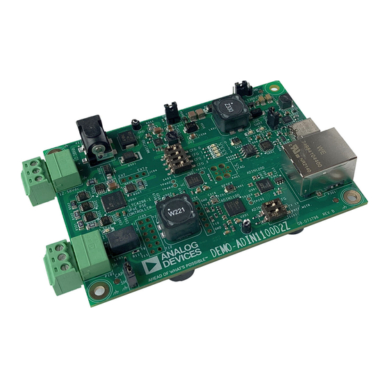
Figure 1. Evaluation Board Photo
UG-2230
Rev. 0 | 1 of 17
Advertisement
Table of Contents

Related Manuals for Analog Devices DEMO-ADIN1100D2Z


Summary of Contents for Analog Devices DEMO-ADIN1100D2Z
-
Page 1: Features
Optional: host with USB interface for management, monitoring, ► The DEMO-ADIN1100D2Z can also be connected via USB to a and diagnostics (also power supply for some classes) host PC. The 10BASE-T1L link status, power status, and diagnos- tics are then accessible using a simple set of text commands and... -
Page 2: Table Of Contents
User Guide DEMO-ADIN1100D2Z TABLE OF CONTENTS Features..............1 Detailed Description..........12 Evaluation Kit Contents......... 1 Media Conversion..........12 Equipment Needed..........1 SPoE PSE............12 Software (Optional)..........1 Microcontroller..........12 General Description..........1 10BASE-T1L/APL Cable Connection....12 Overview..............3 10BASE-T/Ethernet Connection.......12 Firmware Modes of Operation......4 USB COM Port..........12 Board Control Components........5... -
Page 3: Overview
User Guide DEMO-ADIN1100D2Z OVERVIEW Figure 2. Board Connectors and Controls Figure 3. Simplified Block Diagram analog.com Rev. 0 | 3 of 17... -
Page 4: Firmware Modes Of Operation
User Guide DEMO-ADIN1100D2Z OVERVIEW FIRMWARE MODES OF OPERATION Table 1. Firmware Modes of Operation Microcontroller Configuration Class Specification Power for Board Power Supply (mA) Mode Name from USB Note SPoE Class 10 20.7 If USB can supply the power SPoE Class 11 20.8... -
Page 5: Board Control Components
User Guide DEMO-ADIN1100D2Z OVERVIEW BOARD CONTROL COMPONENTS Table 2. Board Control Components Reference Name Description PWR 3V3 The jumper for local 3.3 V power. Keep inserted for normal operation. J101 The jumper for 10BASE-T1L cable shield to connect to earth ground directly or via a 4700 pF capacitor. -
Page 6: Configurations
User Guide DEMO-ADIN1100D2Z CONFIGURATIONS Connect the P101 screw terminal connector via a 10BASE-T1L CONFIGURATION FOR SPOE CLASS 10 cable to a powered device (PD) Class 10. Set Switch S403 for firmware operation Mode 0. Set Switch S201 The board can be supplied from the USB port, if the USB host can for the desired 10BASE-T1L link operation. -
Page 7: Configuration For Spoe Class 11
User Guide DEMO-ADIN1100D2Z CONFIGURATIONS Connect the P101 screw terminal connector via a 10BASE-T1L CONFIGURATION FOR SPOE CLASS 11 cable to a compatible PD Class 12, Class 11, or Class 10. Set Switch S403 for firmware operation Mode 1, and for the rest of... -
Page 8: Configuration For Spoe Class 13
User Guide DEMO-ADIN1100D2Z CONFIGURATIONS Connect P101 screw terminal connector via a 10BASE-T1L cable to CONFIGURATION FOR SPOE CLASS 13 a PD Class 13. Set Switch S403 for firmware operation Mode 3. Set Switch S201 Power supply the board from a (nominal 54 V) power supply source for desired 10BASE-T1L link operation. -
Page 9: Board Modification For Spoe Class 15 And Apl Class 3
User Guide DEMO-ADIN1100D2Z CONFIGURATIONS BOARD MODIFICATION FOR SPOE CLASS 15 AND APL CLASS 3 Figure 7. Modification for SPoE Class 15/APL Class 3—Schematics Snapshot The default power coupling inductor and common-mode inductor on the board have a 900 mA maximum rated current. For the full use... -
Page 10: Configuration For Spoe Class 15
User Guide DEMO-ADIN1100D2Z CONFIGURATIONS from the USB port, insert Jumper J650 and Jumper J651. When CONFIGURATION FOR SPOE CLASS 15 supplying the board from another power supply, Jumper J650 can Perform modifications as described in the Board Modification for be removed to make sure the board power does not come from SPoE Class 15 and APL Class 3 section. -
Page 11: Configuration For Apl Class C
User Guide DEMO-ADIN1100D2Z CONFIGURATIONS CONFIGURATION FOR APL CLASS C CONFIGURATION FOR MEDIA CONVERTER WITH NO POWER Set Switch S403 for firmware operation Mode 8. For all other settings and connections, see the Configuration for APL Class A The board works as a media converter only, the SPoE/APL PSE is section. -
Page 12: Detailed Description
P301 connector. SPOE PSE USB COM PORT The DEMO-ADIN1100D2Z provides SPoE or APL power to a 10BASE-T1L or APL device over the same single pair cable as The DEMO-ADIN1100D2Z USB C connector can be connected to the data. -
Page 13: Ground Connections
GROUND CONNECTIONS 2000 pF of capacitance and approximately 4.7 MΩ of resistance. The DEMO-ADIN1100D2Z board has an earth node. Although this Note that the DEMO-ADIN1100D2Z has been designed only as node may or may not be electrically connected to the earth ground, a demo board. -
Page 14: Software
The DEMO-ADIN1100D2Z can also be connected to a PC via a the DEMO-ADIN1100D2Z S401 RESET button: USB port. The Ethernet links and power status monitoring and... -
Page 15: Status And Diagnostics
User Guide DEMO-ADIN1100D2Z SOFTWARE MSE -37.22 dB, SLCRERR 0.048, Rx 50, Err 0, Vout 23. STATUS AND DIAGNOSTICS 9V, Iout 50.4mA To see repeated welcome message including the firmware mode of stop operation, use the command info. For the status of the Ethernet links, use the command phystatus. - Page 16 User Guide DEMO-ADIN1100D2Z SOFTWARE example for assessing frame error rate on a link in EMC or other Diff 0, Err 0, Vout 13.2V, Iout 3.2mA system level tests. MSE -37.22 dB, SLCRERR 0.048, Tx 3000, Rx 3000, Diff 0, Err 0, Vout 13.2V, Iout 3.1mA...
-
Page 17: Notes
Evaluation Board until you have read and agreed to the Agreement. Your use of the Evaluation Board shall signify your acceptance of the Agreement. This Agreement is made by and between you (“Customer”) and Analog Devices, Inc. (“ADI”), with its principal place of business at Subject to the terms and conditions of the Agreement, ADI hereby grants to Customer a free, limited, personal, temporary, non-exclusive, non-sublicensable, non-transferable license to use the Evaluation Board FOR EVALUATION PURPOSES ONLY.
Need help?
Do you have a question about the DEMO-ADIN1100D2Z and is the answer not in the manual?
Questions and answers