Ingersoll-Rand TRANE Variable Speed ComfortLink II 4TWV0024A1000B Installer's Manual
Heat pumps and air conditioners
Hide thumbs
Also See for TRANE Variable Speed ComfortLink II 4TWV0024A1000B:
- Service facts (72 pages)
Advertisement
Quick Links
Installer's Guide
Variable Speed ComfortLink™ ™ II
Heat Pumps and Air Conditioners
4TWV0024A1000B
4TWV0036A1000B
4TWV0048A1000B
4TWV0060A1000B
Scan to see help
videos on this
product
Only qualified personnel should install and service the equipment. The installation, starting up, and servicing of heating, ventilating, and
air-conditioning equipment can be hazardous and requires specific knowledge and training. Improperly installed, adjusted or altered
equipment by an unqualified person could result in death or serious injury. When working on the equipment, observe all precautions in the
literature and on the tags, stickers, and labels that are attached to the equipment.
June 2018
4TTV0024A1000B
4TTV0036B1000B
4TTV0048A1000B
4TTV0060A1000B
4TTV0061A1000B
S S A A F F E E T T Y Y W W A A R R N N I I N N G G
1 1 8 8 - - B B C C 8 8 9 9 D D 1 1 - - 1 1 H H - - E E N N
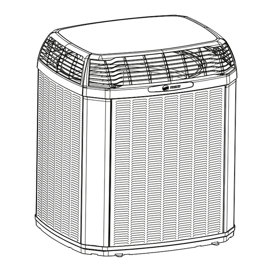
N N o o t t e e : : "Graphics in this document are for representation
only. Actual model may differ in appearance."
Advertisement

Subscribe to Our Youtube Channel
Related Manuals for Ingersoll-Rand TRANE Variable Speed ComfortLink II 4TWV0024A1000B


Summary of Contents for Ingersoll-Rand TRANE Variable Speed ComfortLink II 4TWV0024A1000B
- Page 1 Installer’s Guide Variable Speed ComfortLink™ ™ II Heat Pumps and Air Conditioners 4TWV0024A1000B 4TTV0024A1000B 4TWV0036A1000B 4TTV0036B1000B 4TWV0048A1000B 4TTV0048A1000B 4TWV0060A1000B 4TTV0060A1000B 4TTV0061A1000B N N o o t t e e : : “Graphics in this document are for representation only. Actual model may differ in appearance.” Scan to see help videos on this product...
- Page 2 SAFETY SECTION — OUTDOOR I I m m p p o o r r t t a a n n t t — This document contains a wiring diagram C C A A U U T T I I O O N N and service information.
- Page 3 S S A A F F E E T T Y Y S S E E C C T T I I O O N N — — O O U U T T D D O O O O R R WARNING CAUTION - HOT SURFACE 400 VOLTS...
-
Page 4: Table Of Contents
Table of Contents Unit Location Considerations ....5 Electrical — High Voltage ....18 . -
Page 5: Unit Location Considerations
Unit Location Considerations Table 2. Unit Dimensions and Weight H x D x W (in) Weight * (lb) Models 4TWV0024A 48 x 30 x 33 4TWV0036A 50 x 34 x 37 4TWV0048A 50 x 34 x 37 4TWV0060A 54 x 34 x 37 4TTV0024A 48 x 30 x 33 4TTV0036B... - Page 6 U U n n i i t t L L o o c c a a t t i i o o n n C C o o n n s s i i d d e e r r a a t t i i o o n n s s Table 4.
-
Page 7: Coastal Considerations
U U n n i i t t L L o o c c a a t t i i o o n n C C o o n n s s i i d d e e r r a a t t i i o o n n s s Table 6. -
Page 8: Unit Preparation
Unit Preparation 1. Check for damage and report promptly to the carrier any damage found to the unit. 2. To remove the unit from the pallet, remove tabs by cutting with a sharp tool. Setting Up the Unit Table 7. Pad Installation When installing the unit on a support pad, such as a concrete slab, consider the following: •... -
Page 9: Refrigerant Line Considerations
Refrigerant Line Considerations Table 8. Required Refrigerant Line Length Determine required line length and lift. You will need this to determine the subcooling charging corrections later in the installation process. Total Line Length = ___________________________Ft. Total Vertical Change (lift) = ____________________Ft. Table 9. - Page 10 R R e e f f r r i i g g e e r r a a n n t t L L i i n n e e C C o o n n s s i i d d e e r r a a t t i i o o n n s s Table 10.
- Page 11 R R e e f f r r i i g g e e r r a a n n t t L L i i n n e e C C o o n n s s i i d d e e r r a a t t i i o o n n s s Table 13.
-
Page 12: Refrigerant Line Brazing
Refrigerant Line Brazing Table 15. Braze the Refrigerant Lines Remove caps or plugs. Use a deburring tool to debur the pipe ends. Clean both internal and external surfaces of the tubing using an emery cloth. Remove the pressure tap cap and valve core from each service valves. - Page 13 R R e e f f r r i i g g e e r r a a n n t t L L i i n n e e B B r r a a z z i i n n g g Table 15.
-
Page 14: Refrigerant Line Leak Check
Refrigerant Line Leak Check Table 16. Check for Leaks 150 PSIG Pressurize the refrigerant lines and evaporator coil to 150 PSIG using dry nitrogen. Check for leaks by using a soapy solution at each brazed location. Note: Remove nitrogen pressure and repair any leaks before continuing. -
Page 15: Charging: Weigh-In Method
Charging: Weigh-In Method Weigh-In Method can be used for the initial installation, or anytime a system charge is being replaced. Weigh-In Method can also be used when power is not available to the equipment site or operating conditions (indoor/outdoor temperatures) are not in range to verify with the subcooling charging method. -
Page 16: Service Valves
Service Valves Table 21. Open the Gas Service Valve 1/4 Turn Only Important: Leak check and evacuation must be completed before opening the service valves. Counterclockwise Note: Do not vent refrigerant gases into the atmosphere. for Full Open Position Remove valve stem cap. Using a wrench, turn valve stem 1/4 turn counterclockwise to the fully open position. -
Page 17: Electrical - Low Voltage
Electrical — Low Voltage Communicating Table 23. Low Voltage Maximum Wire Length Table 23, p. 17defines the size and combined total maximum length of low CONTROL WIRING voltage wiring from the outdoor unit, to the indoor unit, and to the thermostat. WIRE SIZE MAX. -
Page 18: Electrical - High Voltage
Electrical — High Voltage Table 25. High Voltage Power Supply W W A A R R N N I I N N G G L L I I V V E E E E L L E E C C T T R R I I C C A A L L C C O O M M P P O O N N E E N N T T S S ! ! F F a a i i l l u u r r e e t t o o f f o o l l l l o o w w t t h h i i s s W W a a r r n n i i n n g g c c o o u u l l d d r r e e s s u u l l t t i i n n p p r r o o p p e e r r t t y y d d a a m m a a g g e e , , s s e e v v e e r r e e p p e e r r s s o o n n a a l l i i n n j j u u r r y y , , o o r r d d e e a a t t h h . -
Page 19: Integrated Variable Speed Control Board
Integrated Variable Speed Control Board LED Indicators The Status (Green) and High COMM (Amber) LEDs are Voltage EXT.ODT to Condensor located in the upper right LSOV COMM (not used) COMM region of the Control STATUS STATUS Board. PERSONALITY MODULE LOAD SHED T1 T2 Fault messages are... -
Page 20: Start Up
Start Up Ensure you have completed the following sections. “Refrigerant Line Brazing,” p. 12 through “Electrical — High Voltage,” p. 18 Set System Thermostat to OFF. Turn on disconnect(s) to apply power to the indoor and outdoor units. Wait 3 hours before starting the unit if the outdoor ambient temperature is below 85°... -
Page 21: System Charge Adjustment
System Charge Adjustment Table 28. Temperature Measurements Check the outdoor temperatures. 120° F Subcooling using “Charging Mode-Cooling” is the only recommended method of charging between 55 ° F and 120° F ambient 55° F outdoor temperature. For best results the indoor temperature should be kept between 70° F to 80°... -
Page 22: Subcool Charging Correction Charts
Subcool Charging Correction Charts Figure 2. Subcool Charging Corrections — 2.0 Ton 2.0 TON SUBCOOL CHARGING CHART CORRECTIONS TABLE (FOR LINE LENGTH AND RISE) Add 1° Add 2° Add 1° Use Design Subcooling 100 110 120 130 140 150 TOTAL REFRIGERANT LINE LENGTH (FEET) Figure 3. - Page 23 S S u u b b c c o o o o l l C C h h a a r r g g i i n n g g C C o o r r r r e e c c t t i i o o n n C C h h a a r r t t s s R-410A REFRIGERANT CHARGING CHART 18-BC89D1-1H-EN...
-
Page 24: Charging The Unit
Charging the Unit I I m m p p o o r r t t a a n n t t : : ENSURE INDOOR BLOWER IS CONFIGURED FOR 400 CFM/TON Table 30. Proper Gage Pressure Using the Standard R-410A Subcool Charging Chart, adjust refrigerant level to attain proper gage pressure. -
Page 25: Communicating Display Assembly (Cda)
Communicating Display Assembly (CDA) NAVIGATION • To enter and exit Technician Menus, press the Up/Down buttons simultaneously for 5 seconds. • To return to the Home Screen, press the Up/Down buttons SYSTEM STATUS simultaneously for 5 seconds. • To return to the top level of any menu, press the Left/Right buttons XXXXXXXXXXXXXXXX simultaneously for 5 seconds. -
Page 26: Defrost Control (Heat Pump Only)
Defrost Control (Heat Pump only) D D e e m m a a n n d d D D e e f f r r o o s s t t C C D D A A N N a a v v i i g g a a t t i i o o n n t t o o F F o o r r c c e e d d D D e e f f r r o o s s t t The demand defrost control measures heat pump Figure 6. -
Page 27: Checkout Procedures
Checkout Procedures The final phase of the installation is the system Checkout Procedures. The following list represents the most common items covered in a Checkout Procedure. Confirm all requirements in this document have been met. ☐ All wiring connections are tight and properly secured. ☐... - Page 28 Ingersoll Rand (NYSE: IR) advances the quality of life by creating comfortable, sustainable and efficient environments. Our people and our family of brands — including Club Car ® , Ingersoll Rand ® , Thermo King ® Trane ® — work together to enhance the quality and comfort of air in homes and buildings; transport and protect food and perishables;...
Need help?
Do you have a question about the TRANE Variable Speed ComfortLink II 4TWV0024A1000B and is the answer not in the manual?
Questions and answers