
Related Manuals for Ingersoll-Rand Trane R Series


Summary of Contents for Ingersoll-Rand Trane R Series
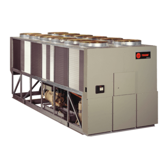
- Page 1 Installation Operation Maintenance Air-Cooled Series R™ Helical-Rotary condensing unit Model RTAC-S 120 to 200 (400 to 750 kW – 50 Hz) RLC-SVX16A-E4 March 2013 © 2013 Trane RLC-SVX16A-E4 Addendum to RTAC chiller IOM RLC-SVX02*-E4...
-
Page 2: Warnings And Cautions
The Trane Model RTAC Air-Cooled Helical-Rotary Condensing unit is based on the reliability, higher energy efficiency, and lower sound levels of RTAC chiller range. This document include additional requirement and is a complement of the RTAC IOM ref RLC-SVX02 Foreword These instructions are given as a guide to good practice in the installation, start-up, operation, and maintenance by the user, of Trane RTAC. -
Page 3: Maintenance Contract
Maintenance contract It is strongly recommended that you sign a maintenance contract with your local Service Agency. This contract provides regular maintenance of your installation by a specialist in our equipment. Regular maintenance ensures that any malfunction is detected and corrected in good time and minimizes the possibility that serious damage will occur. Finally, regular maintenance ensures the maximum operating life of your equipment. - Page 4 Introduction General data Installation Wiring Operation Maintenance Installation checklist © 2013 Trane RLC-SVX16A-E4...
- Page 5 Table 1 - RTAC-S High Efficiency Standard noise Size Refrigerant R134a R134a R134a R134a R134a R134a R134a Performances (1) Gross cooling capacity(1) (kW) Power input in cooling(1) (kW) Main Power supply 400/3/50 400/3/50 400/3/50 400/3/50 400/3/50 400/3/50 400/3/50 Compressor Number Type Screw Screw...
- Page 6 Table 1 - RTAC-S High Extra Efficiency Standard noise Size Refrigerant R134a R134a R134a R134a R134a R134a R134a Performances (1) Gross cooling capacity(1) (kW) Power input in cooling(1) (kW) Main Power supply 400/3/50 400/3/50 400/3/50 400/3/50 400/3/50 400/3/50 400/3/50 Compressor Number Type Screw...
- Page 7 Recommended installation components are shown in Figure 1. The system may be configured in any of the 3 arrangements shown in Figure 2.The configurations and their associated elevations, along with the total distance between the remote evaporator and the compressor/condenser section, play a critical role in determining suction and liquid line sizes.
- Page 8 Figure 1 – Typical piping installation RTAC-S Discharge line Screw Condenser Compressor coil Suction shut off valve Oil separator Suction line Service valve Liquid shut off valve Liquid line Liquid filter Liquid Electronic Liquid filter Solenoid expansion valve Valve With integrated DX evaporator sight glass...
- Page 9 Figure 2 - Piping arrangement considerations Units at same level DX evaporator RTAC-S Air handler Condensing unit Suction line Liquid line Slope 0.4% RTACS below Evaporator DX evaporator Air handler Slope 0.4% RTAC-S Condensing unit Liquid line Slope 0.4% Suction line RTACS above Evaporator RTAC-S Condensing unit...
- Page 10 Unit is shipped with Nitrogen charge. In order to estimate the refrigerant charge of each circuit, proceed with following calculation : R134a system charge = ACCUKG + PIPEKG + EVPKG With : ACCUKG = Refrigerant content of RTAC-S unit (Table 2) PIPEKG = Sum of kg of R-134a added for field-installed piping : Suction + liquid line (Table 3) EVPKG = DX Evaporator refrigerant charge.
- Page 11 Control wiring Typical field wiring is shown in Figure 3 Unit commissioning shall be done by Local Trane technician in order to properly setup connected LLID (Low Level Intelligence Device). Item factory provided, loose supplied with RTAC-S unit are the following LLID devices: 2 temperature sensors: 1 return air Temperature + 1 leaving air Temperature 2 electronic expansion valves: 1 Circuit #1 EXV+ 1 Circuit #2 EXV Temperature sensor and EXV has to be connected with LLID connectors.
- Page 12 Figure 3 – Field control wiring CH530 LLID cable 4x1mm² copper wire shielded cable RTAC-S Condensing unit Unit Control panel 2 Liquid Solenoid Valves Airflow status (fan fail switch) (Rating 110VAC) (rating 110VAC – 1mA) Electronic Expansion valve DX evaporator Air handler Circuit #1 Circuit #2...
- Page 13 Unit operation procedure is identical as RTAC Chiller (Refer to RTAC IOM ref RLC-SVX02) Control System The unit capacity control is identical as for the chiller version. Water temperature values have to be interpreted as evaporator air temperatures,especially through BAS data point list interpretation: Entering water temperature is replaced by evaporator entering air dry bulb temperature.
- Page 14 The following maintenance instructions are part of maintenance operations required for this equipment. A qualified technician is needed for regular maintenance as part of a regular maintenance contract. Carry out all operations as required by schedule. This will insure long unit service life and reduce the possibility of serious and costly breakdown.
-
Page 15: Remove Packaging
RTAC-S Trane Air Cooled Condensing Unit This list must be checked off by the installer to ensure correct installation before the unit starts up. Unit acceptance Check for damage, if any, on transportation Check for equipment shipped against delivery slip ... - Page 16 Trane optimizes the performance of homes and buildings around the world. A business of Ingersoll Rand, the leader in creating and sustaining safe, comfortable and energy efficient environments, Trane offers a broad portfolio of advanced controls and HVAC systems, comprehensive building services, and parts. For more information, visit www.Trane.com.
Need help?
Do you have a question about the Trane R Series and is the answer not in the manual?
Questions and answers