Table of Contents
Advertisement
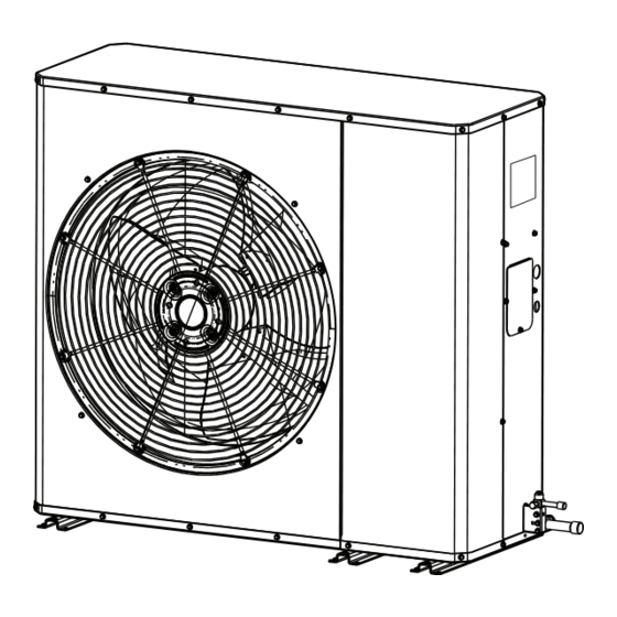
Installer's Guide
Variable Speed AccuLink™ ™
Side Discharge HP Models
For coastal applications where units are installed within one (1) mile of salt water, epoxy coated models are recommended.
These models have an 8 week lead time after order.
4A6L9024A1000A
4A6L9036A1000A
4A6L9048A1000A
4A6L9060A1000A
Only qualified personnel should install and service the equipment. The installation, starting up, and servicing of heating, ventilating, and
air-conditioning equipment can be hazardous and requires specific knowledge and training. Improperly installed, adjusted or altered
equipment by an unqualified person could result in death or serious injury. When working on the equipment, observe all precautions in the
literature and on the tags, stickers, and labels that are attached to the equipment.
October 2018
E E p p o o x x y y C C o o a a t t e e d d M M o o d d e e l l
4A6L9024A1COTA
4A6L9036A1COTA
4A6L9048A1COTA
4A6L9060A1COTA
S S A A F F E E T T Y Y W W A A R R N N I I N N G G
1 1 1 1 - - B B C C 4 4 2 2 D D 1 1 - - 1 1 B B - - E E N N
N N o o t t e e : : "Graphics in this document are for representation
only. Actual model may differ in appearance."
Advertisement
Table of Contents

Subscribe to Our Youtube Channel
Related Manuals for Ingersoll-Rand American Standard 4A6L9024A1000A


Summary of Contents for Ingersoll-Rand American Standard 4A6L9024A1000A
- Page 1 Installer’s Guide Variable Speed AccuLink™ ™ Side Discharge HP Models For coastal applications where units are installed within one (1) mile of salt water, epoxy coated models are recommended. These models have an 8 week lead time after order. E E p p o o x x y y C C o o a a t t e e d d M M o o d d e e l l 4A6L9024A1000A 4A6L9024A1COTA 4A6L9036A1000A...
- Page 2 Safety Section-VSPD Side Discharge I I m m p p o o r r t t a a n n t t — This document contains a wiring diagram C C A A U U T T I I O O N N and service information.
- Page 3 S S a a f f e e t t y y S S e e c c t t i i o o n n - - V V S S P P D D S S i i d d e e D D i i s s c c h h a a r r g g e e Important: If using other than copper pipe, follow manufacturer’s installation instructions.
-
Page 4: Table Of Contents
Table of Contents Unit Location Considerations ....5 LED Indicators — Variable Speed Side Discharge Drive ......18 Setting Up the Unit . -
Page 5: Unit Location Considerations
Unit Location Considerations Table 2. Unit Dimensions (in inches) and Weight Net Weight H x D x W (in) Models (lb) 4A6L9024A1XXX 36.75 x 17 1/2 x 47 32.75 47.0 36.75 17.5 19.5 20.5 4A6L9036A1XXX 36.75 x 17 1/2 x 47 32.75 47.0 36.75... - Page 6 U U n n i i t t L L o o c c a a t t i i o o n n C C o o n n s s i i d d e e r r a a t t i i o o n n s s Table 3.
- Page 7 U U n n i i t t L L o o c c a a t t i i o o n n C C o o n n s s i i d d e e r r a a t t i i o o n n s s Table 3.
-
Page 8: Setting Up The Unit
U U n n i i t t L L o o c c a a t t i i o o n n C C o o n n s s i i d d e e r r a a t t i i o o n n s s Table 5. -
Page 9: Refrigerant Line Considerations
Refrigerant Line Considerations Table 8. Refrigerant Line and Service Valve Connection Sizes Rated Line Sizes Alternate Line Sizes Service Valve Connection Sizes Vapor Line Liquid Line Vapor Line Liquid Line Vapor Line Liquid Line Model Connection Connection 4A6L9024A1XXX 5/8, 3/4 4A6L9036A1XXX 4A6L9048A1XXX 3/4, 7/8... - Page 10 R R e e f f r r i i g g e e r r a a n n t t L L i i n n e e C C o o n n s s i i d d e e r r a a t t i i o o n n s s Table 12.
- Page 11 R R e e f f r r i i g g e e r r a a n n t t L L i i n n e e C C o o n n s s i i d d e e r r a a t t i i o o n n s s Table 15.
-
Page 12: Refrigerant Line Brazing
Refrigerant Line Brazing Table 17. Braze the Refrigerant Lines Remove caps or plugs. Use a deburring tool to debur the pipe ends. Clean both internal and external surfaces of the tubing using an emery cloth. Remove the pressure tap cap and valve core from each service valve. - Page 13 R R e e f f r r i i g g e e r r a a n n t t L L i i n n e e B B r r a a z z i i n n g g Table 17.
-
Page 14: Refrigerant Line Leak Check
R R e e f f r r i i g g e e r r a a n n t t L L i i n n e e B B r r a a z z i i n n g g Refrigerant Line Leak Check Table 18. -
Page 15: Charging: Weigh-In Method
Charging: Weigh-In Method Weigh-In Method can be used for the initial installation, or anytime a system charge is being replaced. Weigh-In Method can also be used when power is not available to the equipment site or operating conditions (indoor/outdoor temperatures) are not in range to verify with the subcooling charging method. -
Page 16: Electrical - Low Voltage
Electrical — Low Voltage Note: The use of color coded low voltage wire is recommended to simplify connections between the outdoor unit, the control, and the indoor unit. Note: The maximum total cable length for the entire comfort control communicating system is 500 ft. 18 AWG. Table 22. -
Page 17: Service Valves
Service Valves Table 24. Open the Gas Service Valve 1/4 Turn Only Important: Leak check and evacuation must be completed before opening the service valves. Counterclockwise Note: Do not vent refrigerant gases into the atmosphere. for Full Open Position Remove valve stem cap. Using a wrench, turn valve stem 1/4 turn counterclockwise to the fully open position. -
Page 18: Discharge Drive
LED Indicators — Variable Speed Side Discharge Drive L L E E D D ’ ’ S S RATE DESCRIPTION INDICATION SLOW 1 TIME PER SECOND STANDBY/IDLE MEDIUM 2 TIMES PER SECOND CALL FOR CAPACITY STATUS (GREEN) FAST 5 TIMES PER SECOND POWER UP DELAY SOLID ON TEST MODE... -
Page 19: Electrical - High Voltage
Electrical — High Voltage Table 26. High Voltage Power Supply W W A A R R N N I I N N G G L L I I V V E E E E L L E E C C T T R R I I C C A A L L C C O O M M P P O O N N E E N N T T S S ! ! F F a a i i l l u u r r e e t t o o f f o o l l l l o o w w t t h h i i s s W W a a r r n n i i n n g g c c o o u u l l d d r r e e s s u u l l t t i i n n p p r r o o p p e e r r t t y y d d a a m m a a g g e e , , s s e e v v e e r r e e p p e e r r s s o o n n a a l l i i n n j j u u r r y y , , o o r r d d e e a a t t h h . -
Page 20: Start Up
Start Up Ensure you have completed the following sections. “,” through “,” Set System Thermostat to OFF. Turn on disconnect(s) to apply power to the indoor and outdoor units. Wait 3 hours before starting the unit if the outdoor ambient temperature is below 85°... -
Page 21: System Charge Adjustment
System Charge Adjustment Table 29. Temperature Measurements Check the outdoor temperatures. 120° F Subcooling using “Charging Mode-Cooling” is the only recommended method of charging between 55 ° F and 120° F ambient 55° F outdoor temperature. For best results the indoor temperature should be kept between 70° F to 80°... -
Page 22: Charging And Correction Charts
Charging and Correction Charts R-410A REFRIGERANT CHARGING CHART DESIGN SUBCOOLING (°F) LIQUID TEMP (°F) LIQUID GAGE PRESSURE (PSI) Table 31. Subcool Charging Correction Charts Important: VARIABLE SPEED OUTDOOR UNITS REQUIRE THE INDOOR UNIT BE CONFIGURED FOR 400 CFM/TON 3.0 TON SUBCOOL CHARGING CHART CORRECTIONS TABLE (FOR LINE LENGTH AND RISE) 2.0 TON SUBCOOL CHARGING CHART CORRECTIONS TABLE (FOR LINE LENGTH AND RISE) Add 1°... -
Page 23: Charging The Unit
Charging the Unit Table 32. Stabilize the system Wait 20 minutes for the system condition to stabilize between adjustments. Note: When the Liquid Line Temperature and Gage Pressure 20 MIN. approximately match the chart, the system is properly charged. Remove gauges. Replace service port caps to prevent leaks. - Page 24 C C h h a a r r g g i i n n g g t t h h e e U U n n i i t t Table 35. Proper Gage Pressure Using the “,” adjust refrigerant level to attain proper gage pressure. Add refrigerant if the Liquid Gage Pressure is lower than the chart value.
-
Page 25: Communicating Display Assembly
Communicating Display Assembly (CDA) NAVIGATION • To enter and exit Technician Menus, press the Up/Down buttons simultaneously for 5 seconds. • To return to the Home Screen, press the Up/Down buttons SYSTEM STATUS simultaneously for 5 seconds. • To return to the top level of any menu, press the Left/Right buttons XXXXXXXXXXXXXXXX simultaneously for 5 seconds. - Page 26 C C o o m m m m u u n n i i c c a a t t i i n n g g D D i i s s p p l l a a y y A A s s s s e e m m b b l l y y ( ( C C D D A A ) ) 1.
-
Page 27: Checkout Procedures
Checkout Procedures The final phase of the installation is the system Checkout Procedures. The following list represents the most common items covered in a Checkout Procedure. Confirm all requirements in this document have been met. ☐ All wiring connections are tight and properly secured. ☐... - Page 28 Ingersoll Rand (NYSE: IR) advances the quality of life by creating comfortable, sustainable and efficient environments. Our people and our family of brands — including Club Car ® , Ingersoll Rand ® , Thermo King ® Trane ® — work together to enhance the quality and comfort of air in homes and buildings; transport and protect food and perishables;...
Need help?
Do you have a question about the American Standard 4A6L9024A1000A and is the answer not in the manual?
Questions and answers