Table of Contents
Advertisement
Quick Links
ALL phases of this installation must comply with NATIONAL, STATE AND LOCAL CODES.
IMPORTANT — This Document is customer property and is to remain with this unit. Please return to service informa-
tion pack upon completion of work.
These instructions do not cover all variations in systems or provide for every possible contingency to be met in connection with
the installation. Should further information be desired or should particular problems arise which are not covered sufficiently for the
purchaser's purposes, the matter should be referred to your installing dealer or local distributor.
Note: The manufacturer recommends installing only approved matched indoor and outdoor systems. All of the manufacture's split
systems are AHRI rated with Piston/TXV/EEV indoor systems. Some of the benefits of installing approved matched indoor and
outdoor split systems are maximum efficiency, optimum performance and the best overall system reliability.
Models
A4AC4018A1000A
A4AC4023A1000A
A4AC4024A1000A
A4AC4030A1000A
A4AC4036A1000A
A4AC4042A1000A
A4AC4048A1000A
A4AC4060A1000A
Only qualified personnel should install and service the equipment. The installation, starting up, and servicing of
heating, ventilating, and air-conditioning equipment can be hazardous and requires specific knowledge and train-
ing. Improperly installed, adjusted or altered equipment by an unqualified person could result in death or serious in-
jury. When working on the equipment, observe all precautions in the literature and on the tags, stickers, and labels
that are attached to the equipment.
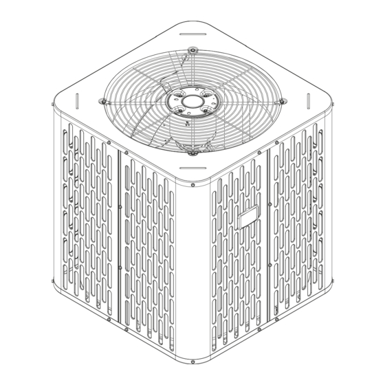
Installer's Guide
Condensing Units
WARNING
s
!
88-A4AC4001-1A-EN
Advertisement
Table of Contents

Related Manuals for Ingersoll-Rand A4AC4018A1000A


Summary of Contents for Ingersoll-Rand A4AC4018A1000A
- Page 1 Note: The manufacturer recommends installing only approved matched indoor and outdoor systems. All of the manufacture’s split systems are AHRI rated with Piston/TXV/EEV indoor systems. Some of the benefits of installing approved matched indoor and outdoor split systems are maximum efficiency, optimum performance and the best overall system reliability. Models A4AC4018A1000A A4AC4023A1000A A4AC4024A1000A A4AC4030A1000A...
-
Page 2: Section 1. Safety
Section 1. Safety WARNING WARNING LIVE ELECTRICAL COMPONENTS! This information is intended for use by individuals During installation, testing, servicing, and trouble- possessing adequate backgrounds of electrical and shooting of this product, it may be necessary to work mechanical experience. Any attempt to repair a central with live electrical components. -
Page 3: Table Of Contents
Table of Contents Section 1. Safety ................................2 Section 2. Unit Location Considerations ........................4 Section 3. Unit Preparation............................5 Section 4. Setting the Unit ............................6 Section 5. Refrigerant Line Considerations ........................ 6 Section 6. Refrigerant Line Routing ..........................8 Section 7. -
Page 4: Section 2. Unit Location Considerations
Section 2. Unit Location Considerations 2.1 Unit Dimensions and Weight Table 2.1 Unit Dimensions and Weight Models H x D x W (in) Weight* (lb) A4AC4018A 28.6 x 23.6 x 23.6 A4AC4023A 32.6 x 23.6 x 23.6 A4AC4024A 28.6 x 25.6 x 25.6 A4AC4030A 28.6 x 29.8 x 29.8 A4AC4036A... -
Page 5: Section 3. Unit Preparation
2.3 Suggested Locations for Best Reliability Ensure the top discharge area is unrestricted for at least five (5) feet above the unit. Avoid Install Near Bedrooms Three (3) feet clearance must be provided in front of the control box (access panels) and any Min 5’... -
Page 6: Section 4. Setting The Unit
Section 4. Setting the Unit 4.1 Pad Installation When installing the unit on a support pad, such as a concrete slab, consider the following: • The pad should be at least 1” larger than the unit on all sides. • The pad must be separate from any structure. •... - Page 7 5.3 Required Refrigerant Line Length Determine required line length and lift. You will need this later in STEP 2 of Section 14. Total Line Length = __________ Ft. Line Length Total Vertical Change (lift) = __________ Ft. 5.4 Refrigerant Line Insulation Important: The Vapor Line must always be Vapor Line insulated.
-
Page 8: Section 6. Refrigerant Line Routing
Section 6. Refrigerant Line Routing 6.1 Precautions Important: Take precautions to prevent noise Comply with National, State, and Local Codes when within the building structure due to vibration isolating line sets from joists, rafters, walls, or other transmission from the refrigerant lines. structural elements. -
Page 9: Section 7. Refrigerant Line Brazing
Wall Sealant Ductwork Insulation Vapor Line Isolator Line Set Isolation Through Wall DO NOT hang line sets from ductwork Section 7. Refrigerant Line Brazing 7.1 Braze The Refrigerant Lines STEP 1 - Remove caps or plugs. Use a debur- ing tool to debur the pipe ends. Clean both internal and external surfaces of the tubing using an emery cloth. - Page 10 STEP 3 - Purge the refrigerant lines and indoor coil with dry nitrogen. STEP 4 - Wrap a wet rag around the valve body to avoid heat damage and continue the dry nitro- gen purge. Braze the refrigerant lines to the service valves. Continue the dry nitrogen purge.
-
Page 11: Section 8. Refrigerant Line Leak Check
Section 8. Refrigerant Line Leak Check 8.1 Check For Leaks STEP 1 - Pressurize the refrigerant lines and 150 PSIG evaporator coil to 150 PSIG using dry nitrogen. STEP 2 - Check for leaks by using a soapy solu- tion or bubbles at each brazed location. Remove nitrogren pressure and repair any leaks before continuing. -
Page 12: Section 10. Service Valves
STEP 2 - Observe the micron gauge. Evacuation is complete if the micron gauge does not rise above 500 microns in one (1) minute. 1 MIN. Once evacuation is complete blank off the vacuum pump and micron gauge, and close the valves on the manifold gauge set. -
Page 13: Section 11. Electrical - Low Voltage
Section 11. Electrical - Low Voltage 11.1 Low Voltage Maximum Wire Length Table 11.1 Table 11.1 defines the maximum total length of low voltage wiring from the outdoor unit, to the 24 VOLTS indoor unit, and to the thermostat. WIRE SIZE MAX. -
Page 14: Section 12. Electrical - High Voltage
Section 12. Electrical - High Voltage 12.1 High Voltage Power Supply WARNING LIVE ELECTRICAL COMPONENTS! During installation, testing, servicing, and troubleshooting of this product, it may be nec- essary to work with live electrical components. Failure to follow all electrical safety precau- tions when exposed to live electrical compo- nents could result in death or serious injury. -
Page 15: Section 13. Start Up
Section 13. Start Up 13.1 System Start Up STEP 1 - Ensure Sections 7 through 12 have been completed. STEP 2 - Set System Thermostat to OFF. DONE CANCEL STEP 3 - Turn on disconnect(s) to apply power to the indoor and outdoor units. STEP 4 - Wait one (1) hour before starting the unit if compressor crankcase heater acces- sory is used and the Outdoor Ambient is below... -
Page 16: Section 14. System Charge Adjustment (Systems Can Be Rated With Txv, Eev Or Piston)
Section 14. System Charge Adjustment (Systems can be rated with TXV, EEV or Piston) NOTE: For systems using a indoor piston metering device, refer to the Superheat charging method and chart. For systems using a TXV or EEV indoor metering device, refer to Subcool charging method and charts. 14.1 Temperature Measurements STEP 1 - Check the outdoor temperatures. - Page 17 STEP 2 - Determine the final subcooling value using total Line Length and Lift measured in STEP 1 and the charts below. 1 1/2 Ton 2 Ton SUBCOOL CHARGING CHART CORRECTIONS TABLE (FOR LINE LENGTH AND RISE) SUBCOOL CHARGING CHART CORRECTIONS TABLE (FOR LINE LENGTH AND RISE) Add 3°...
- Page 18 STEP 4 - Measure the liquid line temperature and pressure at the outdoor unit’s service valve. Measured Liquid Line Temp = __________ º F Liquid Gage Pressure = __________ PSI Final Subcooling Value = __________ º F 107 °F STEP 5 - Use the final subcooling value, refriger- Table 14.2 ant temperature and pressure from STEP 4, to R-410A REFRIGERANT CHARGING CHART...
- Page 19 STEP 6 - Adjust refrigerant level to attain proper gage pressure. Add refrigerant if the Liquid Gage Pressure is lower than the chart value. 1. Connect gages to refrigerant bottle and unit as illustrated. 2. Purge all hoses. 3. Open bottle. 107 °F 4.
- Page 20 Fixed Orifice Superheat Charging Table Indoor Wet Bulb Temp (F) Outdoor Bulb Temp. Using a digital psychrometer, measure the return air wet-bulb temperature at the unit just before the coil. Also measure the outdoor dry-bulb tem- perature. Use these temperatures to locate the target superheat on the charging table. Do not attempt to charge the system if these conditions fall outside of this charging table.
-
Page 21: Section 15. Checkout Procedures And Troubleshooting
STEP 9 - Record System Information for refer- ence. Record system pressures and temperatures after charging is complete. Measured Suction Line Temp = __________ º F Outdoor model number = _________________ Liquid Gage Pressure = __________ PSI Measured Outdoor Ambient = __________ º F Measured Indoor Ambient = __________ º... - Page 22 15.2 Troubleshooting TROUBLESHOOTING Compressor fails to start Contactor check Is contactor Go To: Compressor won’t run energized? (contacts closed) Check for 24 volts AC across contactor coil Is voltage present at Replace contactor contactor coil? Check control transformer and control fuse Jumper R to Y low Is the control Does the...
- Page 23 TROUBLESHOOTING Compressor won’t run Contactor is closed Check for high voltage to contactor Check for open IOL Is high voltage present (Internal Overload) at T1 and T2 ? Check resistance of C to S and C to R Does the Check power resistance check Allow compressor...
-
Page 24: Section 16. Refrigerant Circuits
SYSTEM FAULTS REFRIGERANT CIRCUIT Head Pressure Too High Head Pressure Too Low Suction Pressure Too High Suction Pressure Too Low Liquid Refrig. Floodback (TXV/EEV) Liquid Refrig. Floodback (Cap. Tube) I.D. Coil Frosting Compressor Runs Inadequate or No Cooling/Htg ELECTRICAL Compressor & O.D. Fan Won’t Start Compressor Will Not Start But O.D. - Page 25 2, 2 1/2 & 3-Ton Units PRINTED FROM D157394P01 3 1/2 & 4-Ton Units PRINTED FROM D158514P01 88-A4AC4001-1A-EN...
- Page 26 5-Ton Units PRINTED FROM D158515P01 88-A4AC4001-1A-EN...
- Page 27 Notes 88-A4AC4001-1A-EN...
- Page 28 Ingersoll Rand has a policy of continuous product and product data improvement and it reserves the right to change design and specifications without notice. 6200 Troup Hwy, Tyler, TX 75707 www.ingersollrandproducts.com © 2019 Ingersoll Rand -- All Rights Reserved 05/19...
Need help?
Do you have a question about the A4AC4018A1000A and is the answer not in the manual?
Questions and answers