Advertisement
Quick Links
© Panduit Corp. 2017
READ ALL INSTRUCTIONS COMPLETELY BEFORE PROCEEDING
CONNECTOR ASSEMBLY
SIMPLEX
FLCSMCXAQY
FLCSMC5BLY
FLCSMC6BLY
FLCSSCBUY
DUPLEX
FLCDMCXAQY
FLCDMC5BLY
FLCDMC6BLY
FLCDSCBUY
Table 1
Standard LC OptiCam Connectors*
Backbone
Boot
Fiber Type
Color
Color
10Gig 50µm
Aqua
Aqua
50µm
Black
Black
62.5µm
Electric Ivory
Black
Singlemode
Blue
*Part numbers shown above
ITEMS REQUIRED FOR TERMINATION
ITEM
PART NUMBER
1
OCTT
2
FLCC
3
FVFLPC-1.25SMY
4
CST-115
5
FALC
6
FBFSP
7
FJQCVR
8
FGLS
9
FKS
10
FSTY
11
FSWB-C
12
FWP-C
13
PFX-0
14
--
OPTIONAL
FS115**
OPTIONAL
FJQCVRB
**Denotes revision letter.
For Technical Support: www.panduit.com/resources/install_maintain.asp
Part Numbers: FLCSMCXAQY, FLCDMCXAQY, FLCSMC5BLY, FLCSSCBUY,
Keyed Part Numbers: SEE TABLE BELOW
INSTALLATION INSTRUCTIONS
COMPONENT IDENTIFICATION
Connector Body
Dust Cap
Key Type - Backbone Color
Multimode Part Numbers
Singlemode Part Numbers
Key Type - Backbone Color
Multimode Part Numbers
Singlemode Part Numbers
Blue
Key Type - Backbone Color
Multimode Part Numbers
Singlemode Part Numbers
‡
For duplex connectors, replace the first S in the part number (FLCSSCABL) with a D (FLCDSCABL).
^Substitute for multimode fiber type: 6 = 62.5/125µm OM1, 5 = 50/125µm OM2, or X = 10Gig 50/125µm OM3.
DESCRIPTION
OptiCam Termination Tool
LC Cradle for OptiCam Termination Tool (OCTT)
1.25mm Universal Patch Cord for OptiCam Termination Tool (OCTT)
Fiber Cable Jacket Stripper
Alcohol Bottle (empty)
Fiber Buffer Stripper
Fiber Cleaver Tool
Safety Glasses
Fiber Kevlar Shears
Fiber Safety Tab Stickers for fiber scraps
Cleaning Swabs
Lint-Free Wipes
Fine-Tip Marking Pen
Isopropyl Alcohol (Reagent Grade, 90% minimum concentration; not available from Panduit)
LC OptiCam Connector Stripping Template
Replacement Blade for Fiber Cleaver
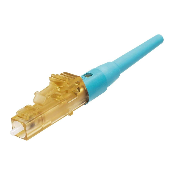
LC OptiCam
Fiber Optic Connectors
FLCDMC5BLY, FLCSMC6BLY, FLCDMC6BLY, FLCDSCBUY
900µm Buffered Boot
Duplex Clip
Keyed LC OptiCam Simplex Connector Part Numbers
A - Black
B - Red
FLCSMC^ABL
FLCSMC^BRD FLCSMC^CGR FLCSMC^DYL FLCSMC^EOR FLCSMC^FDB
FLCSSCABL
FLCSSCBRD
G - Violet
H - Aqua
FLCSMC^GVL
FLCSMC^HAQ FLCSMC^JRO FLCSMC^KIG FLCSMC^LLB FLCSMC^PWT
FLCSSCGVL
FLCSSCHAQ
Q - Charcoal
R - Lavender
FLCSMC^QCG
FLCSMC^RLV FLCSMC^SPE FLCSMC^TSB FLCSMC^VMA FLCSMC^WMI
FLCSSCQCG
FLCSSCRLV
Page 1 of 23
Backbone
Table 2
‡
and Configurations
C - Green
D - Yellow
FLCSSCCGR
FLCSSCDYL
J - Rose
K - Slate
FLCSSCJRO
FLCSSCKIG
S - Peach
T - Steel Blue
FLCSSCSPE
FLCSSCTSB
FS014C
Jacketed Boots
Available Separately
3.0mm Boot
FMCBT3AQ-X
FMCBT3BL-X
FSCBT3BU-X
1.6 - 2.0mm Boot
FMCBT2AQ-X
FMCBT2BL-X
FSCBT2BU-X
E - Orange
F - Dark Blue
FLCSSCEOR
FLCSSCFDB
L - Brown
P - White
FLCSSCLLB
FLCSSCPWT
V - Maroon
W - Mint
FLCSSCVMA
FLCSSCWMI
Advertisement

Subscribe to Our Youtube Channel
Related Manuals for Panduit FLCSMCXAQY


Summary of Contents for Panduit FLCSMCXAQY
- Page 1 Fiber Safety Tab Stickers for fiber scraps FSWB-C Cleaning Swabs FWP-C Lint-Free Wipes PFX-0 Fine-Tip Marking Pen Isopropyl Alcohol (Reagent Grade, 90% minimum concentration; not available from Panduit) OPTIONAL FS115** LC OptiCam Connector Stripping Template OPTIONAL FJQCVRB Replacement Blade for Fiber Cleaver **Denotes revision letter.
-
Page 2: Safety Precautions
2. Clean ferrule adapter end by unscrewing housing and removing split sleeve. Clean the ferrule endface with an alcohol soaked lint-free wipe. Refer to Visual Inspection and Cleaning of Fiber Optic Components Best Practices document FS061* at www.panduit.com. Make sure that the split sleeve is clean. Replace the split sleeve onto ferrule and screw housing into place securely. - Page 3 INSTALLATION INSTRUCTIONS FS014C © Panduit Corp. 2017 250µm Coated Fiber Termination with Build-up Tube To Ensure Best Termination: • If installing more then a few connectors, or if installing OptiCam connectors for the first time or a long time, terminate several connectors and test immediately after to ensure proper technique is being applied.
- Page 4 INSTALLATION INSTRUCTIONS FS014C © Panduit Corp. 2017 5. Strip 250µm Coated Fiber 5.1 Insert the fiber end through the small end of the 250µm Build-up boot. Slide the boot back out of the way. Tube 5.2 Place one build-up tube (F250BT) onto the fiber and slide Boot it back out of the way.
- Page 5 INSTALLATION INSTRUCTIONS FS014C © Panduit Corp. 2017 6.5 Hold the tool in one hand while still holding the fiber against the base plate. Bend the base plate down until the fiber breaks. To prevent contamination, do not set fiber down or allow it to touch anything after cleaving. If fiber does not cleave, go back and re-strip the fiber.
- Page 6 16.2 Clean the ferrule end face with an alcohol soaked wipe, and then a dry wipe. Refer to Visual Inspection and Cleaning of Fiber Optic Components Best Practices Dust cap document FS061* at www.panduit.com. Place dust cap over the ferrule end. 16.2 *Denotes revision letter.
- Page 7 INSTALLATION INSTRUCTIONS FS014C © Panduit Corp. 2017 17. Attach Duplex Clip (Optional) Pocket 17.1 With a connector held as shown (latch on top, ferrule facing away), insert the connector into one side of the duplex clip as shown (clip held with the “A->B” polarity marking upright and facing forward).
- Page 8 INSTALLATION INSTRUCTIONS FS014C © Panduit Corp. 2017 250µm Coated Fiber Termination using Opticom Fanout Kit To Ensure Best Termination: • If installing more then a few connectors, or if installing OptiCam connectors for the first time or a long time, terminate several connectors and test immediately after to ensure proper technique is being applied.
- Page 9 INSTALLATION INSTRUCTIONS FS014C © Panduit Corp. 2017 5. Install Fanout Kit and Strip Fiber 250µm Coated 900µm Fanout Fibers (taut) 5.1 Install the Fanout Kit (FO6CB, FO12CB) according to Tubing 3mm Cable the installation instructions FS047*. 5.2 Feed the 250µm coated fibers through the 900µm fanout tubing until at least 30mm of fiber protrudes from the end of the tubing.
- Page 10 INSTALLATION INSTRUCTIONS FS014C © Panduit Corp. 2017 6. Cleave 250µm Coated Fiber in Fanout Kit 6.1 Remove and dispose of any remaining fiber scraps in the cleaving tool. 6.2 Clean bare fiber using an isopropyl alcohol (90% minimum concentration) soaked lint-free wipe. The fiber should be free of all coating and residue.
- Page 11 INSTALLATION INSTRUCTIONS FS014C © Panduit Corp. 2017 7. Insert Fiber Insertion Mark 7.1 Insert fiber into the connector body using constant light pressure until it stops on the fiber stub. Excessive force during insertion may break the fiber. The fiber should be guided in straight, not at an angle.
- Page 12 INSTALLATION INSTRUCTIONS FS014C © Panduit Corp. 2017 11. Cam the Connector 11.1 Rotate the connector body 90° counter-clockwise around the center axis until it stops on the cradle (when looking from rear of connector). Ensure the connector body remains seated in the cradle during camming.
- Page 13 18.2 Clean the ferrule end face with an alcohol soaked wipe, and then a dry wipe. Refer to Visual Inspection and Cleaning of Fiber Optic Components Best Practices document FS061* at www.panduit.com. 18.1 Place dust cap over the ferrule end.
- Page 14 INSTALLATION INSTRUCTIONS FS014C © Panduit Corp. 2017 900µm Tight-Buffered Fiber Termination To Ensure Best Termination: • If installing more then a few connectors, or if installing OptiCam connectors for the first time or a long time, terminate several connectors and test immediately after to ensure proper technique is being applied. Testing after a few connectors allows verification that the tools are in good working condition and helps to gauge the working conditions of the environment and calibrate glow level thresholds.
- Page 15 INSTALLATION INSTRUCTIONS FS014C © Panduit Corp. 2017 5. Strip 900µm Tight-Buffered Fiber 5.1 Insert the fiber end through the small end of the 900µm boot. Slide the boot back out of the way. 5.2 Use buffer stripper to strip at least 1.18" (30mm) of buffer.
- Page 16 INSTALLATION INSTRUCTIONS FS014C © Panduit Corp. 2017 7. Insert Fiber 7.1 Insert fiber into the connector body using constant light Insertion Mark pressure until it stops on the fiber stub. Excessive force during insertion may break the fiber. The fiber should be guided in straight, not at an angle.
- Page 17 INSTALLATION INSTRUCTIONS FS014C © Panduit Corp. 2017 11. Cam the Connector 11.1 Rotate the connector body 90° counter-clockwise around the center axis until it stops on the cradle (when looking from rear of connector). Ensure the connector body remains seated in the cradle during camming.
- Page 18 18.2 Clean the ferrule end face with an alcohol soaked Flange wipe, and then a dry wipe. Refer to Visual Inspection and Cleaning of Fiber Optic Components Best Practices document FS061* at www.panduit.com. 18.1 Place dust cap over the ferrule end. Dust Cap 19.
- Page 19 INSTALLATION INSTRUCTIONS FS014C © Panduit Corp. 2017 Jacketed Cable Termination To Ensure Best Termination: • If installing more then a few connectors, or if installing OptiCam connectors for the first time or a long time, terminate several connectors and test immediately after to ensure proper technique is being applied. Testing after a few connectors allows verification that the tools are in good working condition and helps to gauge the working conditions of the environment and calibrate glow level thresholds.
- Page 20 INSTALLATION INSTRUCTIONS FS014C © Panduit Corp. 2017 5. Strip Jacketed Cable Jacketed Cable STRIPPING DIMENSIONS 5.1 If using duplex cable, split the two cables approximately IMPORTANT! Due to printing variations, use a rigid 6" (152mm) or as needed. scale for stripping dimensions, or the appropriate 5.2 Following the stripping dimensions, use the marking pen...
- Page 21 INSTALLATION INSTRUCTIONS FS014C © Panduit Corp. 2017 6.4 This is a critical step for successful termination. Gently hold the buffered fiber against the groove in the base plate using thumb and forefinger of your free hand. With your other thumb, gently push down on the...
- Page 22 INSTALLATION INSTRUCTIONS FS014C © Panduit Corp. 2017 8. Clamp Cable Clamp Arm 8.1 Squeeze both clamp arms to open clamp pads. Place cable between the clamp pads and release clamp arms. The fiber should be straight and the insertion Clamp Pads mark should still be in close proximity to the back of the connector.
- Page 23 16.4 Clean the ferrule end face with an alcohol soaked wipe, and then a dry wipe. Refer to Visual Inspection and Cleaning of Fiber Optic Components Best Practices document FS061* at www.panduit.com. Place dust cap over the ferrule end. 17. Attach Duplex Clip (Optional) 17.1 With a connector held as shown (latch on top, ferrule...
Need help?
Do you have a question about the FLCSMCXAQY and is the answer not in the manual?
Questions and answers