Advertisement
Table of Contents
© Panduit Corp. 2007
Wire Cap
Jack
1
0.5"
(12.7mm)
5
Cable End 1
Pr2
Pr1
Pr4
For Technical Support: www.panduit.com/resources/install_maintain.asp
INSTALLATION INSTRUCTIONS PN366E
S-STP / PIMF
Individual Foil
Pair Screen
Conductors
U/FTP
Individual Foil
Strain
Pair Screen
Relief
Collar
Conductors
TERMINATION STEPS
2
Cable
End 1
Cable End 2
Pr4
Pr3
Pr1
TX6 10G
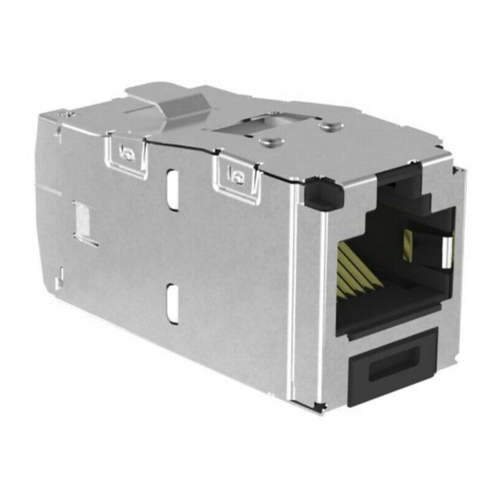
Shielded Jack Module
IG
Part Number: CJS6X88TG, CJS6X88TGY
2.0 in
(50.8 mm)
Braid
2.0 in
(50.8 mm)
Drain Wire
3
Cable
End 2
6
Pr3
Pr2
Page 1 of 2
CWST
Drain
Wire
CWST
4
"
"
"
"
Advertisement
Table of Contents

Summary of Contents for Panduit PN366E
- Page 1 © Panduit Corp. 2007 Strain Relief Collar Wire Cap Jack 0.5" (12.7mm) Cable End 1 For Technical Support: www.panduit.com/resources/install_maintain.asp TX6 10G Shielded Jack Module Part Number: CJS6X88TG, CJS6X88TGY INSTALLATION INSTRUCTIONS PN366E S-STP / PIMF Individual Foil 2.0 in Pair Screen (50.8 mm)
- Page 2 4. On cable end 2 for A & B wiring and cable end 1 of A wiring, wrap the designated pairs around the proper center dividing post (A or B) and terminate in the proper location. 5. CJSGK-X Grounding Kit is REQUIRED for all M 6. For technical and performance information, consult PANDUIT Technical Support. As with all Wiring Accessories, the following statements apply: 1. Never install communications wiring during a lightning storm.


Need help?
Do you have a question about the PN366E and is the answer not in the manual?
Questions and answers