Advertisement
© Panduit Corp. 2017
Conductor holes and contact slots
Contact slots
1
Thread on boot
and collar first!
(Cable ends 1 & 2)
(Cable end 2)
2
BLU
ORG
"V" channel
GRN
BRN
3
"V" channel
(Cable end 1)
For Technical Support: www.panduit.com/resources/install_maintain.asp
INSTALLATION INSTRUCTIONS
T568B Wiring Scheme
(Cable end 2)
(Cable end 1)
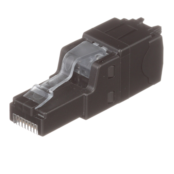
Strain relief collar
Divider
Load bar
Plug housing with shield
Load Bar
Pins
1
8
Conductor holes
CWST
90°
(Cable end 1)
GRN
Drain wire
ORG
"V" channel
BRN
BLU
(Cable end 2)
TX6A Shielded Modular Plug
T568B & T568A
Part Number: SPS6X88-C
Pin #
T568B BRN
Specifications
•
•
Strain relief boot
•
•
Conductor slots and "V" channel
"V" channel
• Thread boot and collar onto cable.
• Remove 1.5" of the outer jacket using wire stripping tool
(CJAST).
• Cut foil flush with cable jacket. If cable is braided, form braid
into a drain wire. Bend the drain wire back so it is against the
cable jacket.
• Fan twisted pairs into respective quadrants. The brown pair
should be opposite the orange pair.
• Cut spline flush to fanned pairs using wire snipping tool
(CWST).
• Align the conductor divider "V" channel with the green pair.
• Insert divider posts into the cable. If the cable has an internal
spline, insert divider posts into the brown and orange
quadrants of the spline.
Drain wire
• Arrange conductors to T568B wiring scheme while minimizing
untwist.
• Seat conductors into proper divider slots while holding divider
flush with cable jacket.
Page 1 of 4
8
7
6
5
BRN/
BLU/
GRN WHT
WHT
Cable jacket diameter maximum 0.300 in (7.6mm).
Solid or stranded conductor maximum insulated diameter
0.047 in (1.2mm).
Panduit recommends T568B wiring scheme for use with
cable constructed with the brown pair opposing the orange
pair.
For use with F/UTP, U/FTP and S/FTP type cables, which
meet the dimensional requirements. Cable must have drain
wire or braid.
Divider
Divider post
PN600A
4
3
2
1
GRN/
ORG/
BLU WHT
ORG WHT
Advertisement
Table of Contents

Related Manuals for Panduit T568B


Summary of Contents for Panduit T568B
- Page 1 Drain wire quadrants of the spline. Drain wire “V” channel “V” channel • Arrange conductors to T568B wiring scheme while minimizing untwist. • Seat conductors into proper divider slots while holding divider flush with cable jacket. “V” channel (Cable end 1) (Cable end 2) For Technical Support: www.panduit.com/resources/install_maintain.asp...
- Page 2 © Panduit Corp. 2017 • Straighten and align untwisted conductors using a circular motion while holding conductors in respective divider slots. • Maintain grip of conductors in T568B wiring scheme. • Trim conductors on an angle approximately 1.00" from divider leading edge.
- Page 3 Cable jacket diameter maximum 0.300 in (7.6mm). • Solid or stranded conductor maximum insulated diameter Strain relief boot 0.047 in (1.2mm). • Panduit recommends T568A wiring scheme for use with cable constructed with the brown pair opposing the green Strain relief collar pair. Divider •...
- Page 4 INSTALLATION INSTRUCTIONS PN600A © Panduit Corp. 2017 • Straighten and align untwisted conductors using a circular motion while holding conductors in respective divider slots. • Maintain grip of conductors in T568A wiring scheme. • Trim conductors on an angle approximately 1.00" from divider leading edge.
Need help?
Do you have a question about the T568B and is the answer not in the manual?
Questions and answers