Advertisement
© Panduit Corp. 2013
Conductor holes and Contact slots
Contact slots
1
Thread on boot
and collar first!
(Cable ends 1 & 2)
(Cable end 2)
2
BLU
ORG
"V" channel
GRN
BRN
3
"V" channel
(Cable end 1)
* Denotes packaging quantity.
For Technical Support: www.panduit.com/resources/install_maintain.asp
INSTALLATION INSTRUCTIONS
T568B Wiring Scheme
Strain Relief Collar
Divider
Plug Housing
Load Bar
Pins
1
8
Conductor holes
CWST
90°
(Cable end 1)
GRN
ORG
BRN
BLU
(Cable end 2)
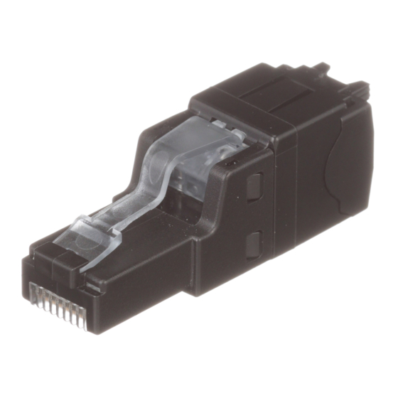
Category 6A UTP Modular Plug
for Panduit Patch Cable
T568B & T568A
Part Number: SP6X88P-*
Strain Relief Boot
Thread boot and collar onto the cable first.
Remove 2.0" of the outer jacket from the cable end using
wire stripping tool (CJAST).
Remove matrix foil to expose twisted pairs.
Fan twisted pairs into respective quadrants. The brown
pair should be opposite the orange pair.
When a cable spline (X-shaped filler) is present, cut spline
flush to fanned pairs using wire snipping tool (CWST).
Note orientation of the divider depending on cable end 1
or cable end 2. The "V" channel should be aligned with the
green pair.
Insert divider posts into the cable. If the cable has an
internal spline, insert divider posts into the brown and
"V" channel
orange quadrants of the spline.
Arrange conductors to T568B wiring scheme while
minimizing untwist and smooth conductors.
Seat conductors into proper divider slots while holding
divider near the end of the cable jacket.
Page 1 of 4
Pin #
8
7
6
BRN/
BLU/
T568B BRN
GRN WHT
WHT
Specifications
• Cable jacket diameter 0.285 in. max.
• Maximum conductor insulation diameter 0.041 in.
• Panduit recommends T568B wiring scheme for use
with cable constructed with the brown pair opposing
the orange pair.
Divider
Conductor slots and "V" channel
"V" channel
PN575B
5
4
3
2
1
GRN/
ORG/
BLU WHT
ORG WHT
Divider post
Advertisement
Table of Contents

Related Manuals for Panduit T568A


Summary of Contents for Panduit T568A
- Page 1 Strain Relief Collar • Cable jacket diameter 0.285 in. max. • Maximum conductor insulation diameter 0.041 in. Divider • Panduit recommends T568B wiring scheme for use Load Bar with cable constructed with the brown pair opposing the orange pair. Plug Housing...
- Page 2 INSTALLATION INSTRUCTIONS PN575B © Panduit Corp. 2013 While holding conductors in respective divider slots, straighten and align untwisted conductors using a circular motion. Do not release grip of conductors until load bar is applied in order to maintain conductor alignment.
- Page 3 • Cable jacket diameter 0.285 in. max. Strain Relief Collar • Maximum conductor insulation diameter 0.041 in. Divider • Panduit recommends T568A wiring scheme for use Load Bar with cable constructed with the brown pair opposing the green pair. Plug Housing...
- Page 4 INSTALLATION INSTRUCTIONS PN575B © Panduit Corp. 2013 While holding conductors in respective divider slots, straighten and align untwisted conductors using a circular motion. Do not release grip of conductors until load bar is applied in order to maintain conductor alignment.
Need help?
Do you have a question about the T568A and is the answer not in the manual?
Questions and answers