Table of Contents
Advertisement
Quick Links
AN54439
PSoC 3 and PSoC 5LP External Crystal
Oscillators
Associated Part Family
All PSoC
®
3 and PSoC 5LP Parts
Software Version
PSoC Creator™ 3.0
About this document
Scope and purpose
AN54439 describes how to use an external crystal or ceramic resonator at 32.768 kHz or in the 4-25 MHz range
with PSoC
3 or PSoC 5LP. External crystal oscillators provide more accurate clock signals than the oscillators
®
built into the PSoC 3 and 5LP devices. These devices also include a wide range of clock dividers, PLLs, and a
clock distribution network that is covered in the
application note.
Table of contents
Associated Part Family .................................................................................................................... 1
Software Version ............................................................................................................................ 1
About this document ....................................................................................................................... 1
Table of contents ............................................................................................................................ 1
1
Introduction .......................................................................................................................... 3
2
PSoC 3 and PSoC 5LP Clocking Overview ................................................................................... 4
3
External Crystal Oscillator Theory ............................................................................................ 5
4
ECO Hardware Implementation ............................................................................................... 6
4.1
Overall ECO Hardware Topology ............................................................................................................ 6
4.2
ECO PCB Layout ....................................................................................................................................... 6
4.3
MHz Resonator ........................................................................................................................................ 7
4.3.1
MHz Resonator Selection ................................................................................................................... 7
4.4
kHz Crystal ............................................................................................................................................... 8
4.4.1
kHz Crystal Selection ......................................................................................................................... 8
4.5
Pi-network Capacitors ............................................................................................................................. 8
4.5.1
Balanced Load Capacitor Example.................................................................................................... 9
5
ECO Firmware Implementation ............................................................................................... 10
5.1
ECOs and the Clock Tree ....................................................................................................................... 10
5.2
Design Wide Resources Settings ........................................................................................................... 11
5.2.1
MHz ECO Automatic Gain Control.................................................................................................... 12
5.2.2
5.2.3
Amplitude Adjustment ..................................................................................................................... 13
Application Note
www.infineon.com
AN60631 PSoC 3 or PSoC 5LP Clocking Resources
Please read the Important Notice and Warnings at the end of this document
page 1 of 26
001-54439 Rev. *M
2021-03-17
Advertisement
Table of Contents

Related Manuals for Infineon PSoC 3


Summary of Contents for Infineon PSoC 3
-
Page 1: Table Of Contents
3 or PSoC 5LP. External crystal oscillators provide more accurate clock signals than the oscillators ® built into the PSoC 3 and 5LP devices. These devices also include a wide range of clock dividers, PLLs, and a clock distribution network that is covered in the AN60631 PSoC 3 or PSoC 5LP Clocking Resources application note. - Page 2 PSoC 3 and PSoC 5LP External Crystal Oscillators Table of contents Real-Time Clock ............................. 14 ECO Performance Testing and Improvement ................15 ECO Performance Metrics ........................15 6.1.1 Negative Resistance ......................... 15 6.1.2 Drive Level ............................15 6.1.3 Startup Time ............................. 16 6.1.4...
-
Page 3: Introduction
Introduction Introduction AN54439 describes how to configure hardware and firmware for PSoC 3 or PSoC 5LP using the integrated oscillator subsystems and external crystal or ceramic resonators. The PSoC 3 and PSoC 5LP microcontrollers can use a variety of clock sources. Among these, there are two oscillators that can be used with external passive components to generate clock signals with more frequency accuracy than the Internal Main Oscillator (IMO) and Internal Low-speed Oscillator (ILO). -
Page 4: Psoc 3 And Psoc 5Lp Clocking Overview
The two clock sources in PSoC 3 and PSoC 5LP that can be replaced by the ECOs are the 3-62 MHz (3-74 MHz on some PSoC 5LP devices) IMO and the 1/33/100 kHz ILO. These two clock sources operate without external components, with a lower accuracy than achievable by the ECOs (+/-1% error for the IMO and -50%, +100% for the ILO). -
Page 5: External Crystal Oscillator Theory
External Crystal Oscillator Theory The kHz and MHz external oscillators in PSoC 3 and PSoC 5LP are Pierce oscillators, meaning an inverting amplifier provides feedback across a crystal in parallel with it. A circuit diagram of a Pierce oscillator is shown Figure 2. -
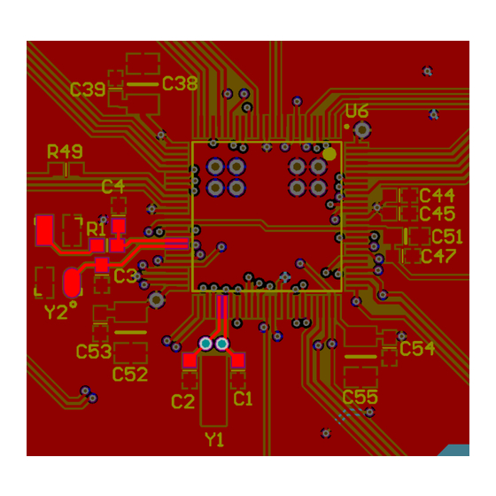
Page 6: Eco Hardware Implementation
To minimize stray capacitance, the crystal and bypass capacitors are placed as close to the PSoC 3 or PSoC 5LP as possible. Optimally, they are on the same side of the PCB as the PSoC 3 or PSoC 5LP, with no unnecessary vias on the XTALin and XTALout traces. -
Page 7: Mhz Resonator
Frequency selection is another important resonator selection factor. The MHz ECO clock may be used as an input to the PSoC 3 and PSoC 5LP phase-locked loop (PLL). This means that the resonator does not need to be the same frequency required for clocking a design with. Lower frequency ECOs have more design tolerance, consume less current, and start up faster. -
Page 8: Khz Crystal
Crystal Selection PSoC 3 and PSoC 5LP’s kHz ECO can operate with parallel resonant 32.768 kHz crystals with a load capacitance of 6 pF or 12.5 pF. Acceptable crystals must meet these guidelines, and also have frequency accuracy and packaging acceptable in the application. -
Page 9: Balanced Load Capacitor Example
2. If we assume PSoC 3 and PSoC 5LP pin input capacitance(CP) of 5 pF and a board trace capacitance (CB) of 1 pF, then the result is 2*12.5-(5+1) = 19 pF, or a standard 18-pF value. Thus, we would place one 18-pF load capacitor on each side of the crystal. -
Page 10: Eco Firmware Implementation
Design Wide Resources interface. ECOs and the Clock Tree The kHz and MHz ECOs can be used in various ways throughout PSoC 3 and PSoC 5LP. The kHz and MHz ECOs are highlighted in the clock tree diagram shown in Figure 5. -
Page 11: Design Wide Resources Settings
PSoC 3 and PSoC 5LP External Crystal Oscillators ECO Firmware Implementation Design Wide Resources Settings The Design Wide Resources interface is used to configure the ECOs in a PSoC Creator project. Within the design wide resources, clocks are configured in the “Clocks” tab. The clock tree may be configured using the “configure system clocks”... -
Page 12: Mhz Eco Automatic Gain Control
Note: The kHz crystal clock frequency is not configurable, because PSoC 3 and PSoC 5LP support only 32.768-kHz crystals. Some design decisions must be made when choosing how to use the ECO clocks. Both MHz and kHz ECO clocks may be used as sources for digital and analog clocks, so no special configuration is required to create an externally based local clock. -
Page 13: Mhz Eco Error Detection "Watchdog
PSoC 3 and PSoC 5LP External Crystal Oscillators ECO Firmware Implementation 5.2.2 MHz ECO Error Detection “Watchdog” The error detection, or “watchdog” circuitry allows the ECOs to detect when each resonator is oscillating properly. This result is used to determine when the ECO has completed startup and can be used to clock the system. -
Page 14: Real-Time Clock
PSoC Creator provides the RTC component, which allows the designer to quickly implement a real-time clock in PSoC 3 and PSoC 5LP using a kHz ECO. For more information about how to implement a Real-Time Clock, refer to the “RTC” Component datasheet in PSoC Creator under the Component Catalog. -
Page 15: Eco Performance Testing And Improvement
PSoC 3 and PSoC 5LP External Crystal Oscillators ECO Performance Testing and Improvement ECO Performance Testing and Improvement When designing microcontroller based systems, reliability is a critical concern. The best way to improve reliability is to test systems over a range of critical variables, slightly exceeding required performance specifications. -
Page 16: Startup Time
Startup time is a measurement of the time it takes for the ECO to stabilize at the desired frequency after it is enabled. This value will vary with both hardware and firmware configuration. Maximum values for these specs are shown in the PSoC 3 and 5LP device datasheets. Example startup times for MHz resonators with PSoC 3 are shown in Figure 9. -
Page 17: Frequency Accuracy
PSoC 3 and PSoC 5LP External Crystal Oscillators ECO Performance Testing and Improvement toggle should be added before the register CYREG_FASTCLK_XMHZ_CSR is set, and another should be added after the following loop, which should be just a few lines of code below it. -
Page 18: Recommended Psoc 3 Mhz Eco Configurations
9. Resonators were tested across operating temperature and supply voltage. The two 24 MHz ECS crystals shown are the same parts used on the PSoC 3 and PSoC 5LP DVKs. The KIT-030 and KIT-050 have the ECS-240-20-5PX-TR, and the KIT-009A and KIT-010 have the ECS-240-12-5PX-TR. -
Page 19: Eco Frequency Accuracy
PSoC 3 and PSoC 5LP External Crystal Oscillators Recommended PSoC 3 MHz ECO Configurations ECO Frequency Accuracy The frequency of the clock generated by the ECO will always deviate from the desired frequency by some amount. It is important to understand how much it will deviate, and how to improve it. This section describes the various factors that impact frequency performance. -
Page 20: Series And Feedback Resistors
PSoC 3 and PSoC 5LP External Crystal Oscillators Recommended PSoC 3 MHz ECO Configurations Note: This formula is a linearization of a second order function. For more details, inquire with crystal vendors. Here is an example of calculation of trim sensitivity for an Abracon AB38T-32.768KHZ crystal. This 32.768 kHz crystal has a typical C1 of 0.0035 pF, typical C0 of 1.6 pF, and rated CL of 12.5 pF. -
Page 21: Unbalanced Eco Load Capacitors
PSoC 3 and PSoC 5LP External Crystal Oscillators Recommended PSoC 3 MHz ECO Configurations Unbalanced ECO Load Capacitors There are two load capacitor configuration options: balanced and unbalanced. In a balanced configuration, both capacitor values are equal. In an unbalanced configuration, one capacitor is larger than the other capacitor. -
Page 22: Using An External Clock Signal On The Eco Pins
PSoC 3 and PSoC 5LP External Crystal Oscillators Recommended PSoC 3 MHz ECO Configurations Figure 12 32-kHz ECO Startup Behavior Using an External Clock Signal on the ECO Pins If the MHz or kHz ECO is not being used, an external clock signal may be routed onto the ECO clock nets using the kHz or MHz crystal input pins. - Page 23 PSoC 3 and PSoC 5LP External Crystal Oscillators Recommended PSoC 3 MHz ECO Configurations To configure the Clock Component’s frequency and source, double click on the Clock Component to open the configuration dialog. To learn more about configuring the Clock Component, refer to the component datasheet by right-clicking on the Clock Component and selecting “Open Datasheet…”...
-
Page 24: Related Application Notes
PSoC 3 and PSoC 5LP External Crystal Oscillators Related Application Notes Related Application Notes AN60616 - PSoC 3 and PSoC 5LP Startup Procedure AN60631 - PSoC 3 and PSoC 5LP Clocking Resources AN2027 - PSoC 1 32.768-kHz External Crystal Oscillator... -
Page 25: Revision History
PSoC 3 and PSoC 5LP External Crystal Oscillators Revision history Revision history Document Date of release Description of changes version 2009-07-02 New Application Note 2009-09-03 Updated project Clarified diagrams 2010-08-20 Updated code Added PSoC 5. 2011-01-04 Added and updated information (low power, startup, R selection, etc.). - Page 26 Infineon Technologies hereby disclaims dangerous substances. For information on the types © 2021 Infineon Technologies AG. any and all warranties and liabilities of any kind in question please contact your nearest Infineon All Rights Reserved. (including without limitation warranties of non- Technologies office.
Need help?
Do you have a question about the PSoC 3 and is the answer not in the manual?
Questions and answers