Infineon XC800 Series User Manual
8-bit single chip microcontroller
Hide thumbs
Also See for XC800 Series:
- Using manual (31 pages) ,
- Application note (22 pages) ,
- Manual (28 pages)

Related Manuals for Infineon XC800 Series


Summary of Contents for Infineon XC800 Series
- Page 1 User’s Manual, V 1 .3, Feb. 2007 XC866 8 - B i t S i n g l e C h i p M i c r o c o n t r o l l e r M i c r o c o n t r o l l e r s...
- Page 2 Infineon Technologies Components may only be used in life-support devices or systems with the express written approval of Infineon Technologies, if a failure of such components can reasonably be expected to cause the failure of that life-support device or system, or to affect the safety or effectiveness of that device or system. Life support devices or systems are intended to be implanted in the human body, or to support and/or maintain and sustain and/or protect human life.
- Page 3 User’s Manual, V 1 .3, Feb. 2007 XC866 8 - B i t S i n g l e C h i p M i c r o c o n t r o l l e r M i c r o c o n t r o l l e r s...
- Page 4 Any information within this document that you feel is wrong, unclear or missing at all? Your feedback will help us to continuously improve the quality of this document. Please send your proposal (including a reference to this document) to: mcdocu.comments@infineon.com...
-
Page 5: Table Of Contents
XC866 Table of Contents Page Introduction ..........1-1 Feature Summary . - Page 6 XC866 Table of Contents Page 3.4.5.9 OCDS Registers ........3-31 Boot ROM Operating Mode .
- Page 7 XC866 Table of Contents Page Register Map ..........6-12 Port 0 .
- Page 8 XC866 Table of Contents Page Register Description ........9-5 Serial Interfaces .
- Page 9 XC866 Table of Contents Page 11.1.2.1 Mode 0 ..........11-3 11.1.2.2 Mode 1 .
- Page 10 XC866 Table of Contents Page 12.3 Register Description ........12-31 12.3.1 System Registers .
- Page 11 XC866 Table of Contents Page 13.7.2 Priority and Arbitration Register ......13-33 13.7.3 External Trigger Control Register .
- Page 12 XC866 Table of Contents Page 15.3.3 LIN Response Protocol to the Host ......15-19 15.3.4 Fast LIN BSL ......... . 15-20 15.3.5 After-Reset Conditions .
-
Page 13: Introduction
XC866 Introduction Introduction The XC866 is a member of the high-performance XC800 family of 8-bit microcontrollers. It is based on the XC800 Core that is compatible with the industry standard 8051 processor. The XC866 features a great number of enhancements to enable new application technologies through its highly integrated on-chip components, such as on-chip oscillator or an integrated voltage regulator, allowing a single voltage supply of 3.3 or 5.0 V. - Page 14 XC866 Introduction The XC866 product family features devices with different configurations and program memory sizes, temperature and quality profiles (Automotive or Industrial), offering cost- effective solution for different application requirements. The configuration of temperature range (T ) for XC866 devices are summarized in Table 1-1 and the configuration of LIN BSL for XC866 devices are summarized in Table...
- Page 15 XC866 Introduction Table 1-3 Device Summary Device Device Name Power P-Flash D-Flash Quality Type Supply Size Size Size Profile (Kbytes) (Kbytes) (Kbytes) SAF-XC866*-2FRI – Industrial SAF-XC866*-1FRA 5.0/3.3 – – Automotive SAF-XC866*-1FRI 5.0/3.3 – – Industrial SAA-XC866*-4FRA 3V 3.3 – Automotive SAA-XC866*-2FRA 3V 3.3 –...
- Page 16 XC866 Introduction • X is aligned based on D-Flash sectors arrangement. • ROM size must be linearly overmapping D-Flash range bottom up. The memory configurations of XC866-4RR ROM device are summarized in Table 1-4. Table 1-4 Memory Configurations of XC866-4RR ROM device Configuration Type ROM Size D-Flash Size...
-
Page 17: Feature Summary
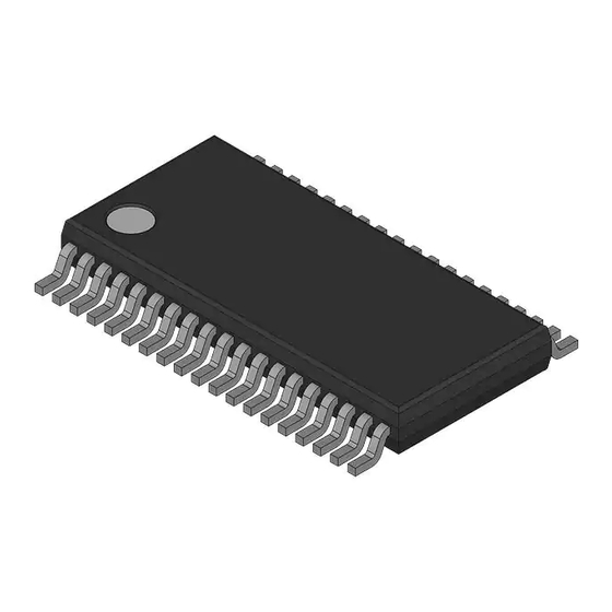
XC866 Introduction Feature Summary The following list summarizes the main features of the XC866: • High-performance XC800 Core – compatible with standard 8051 processor – two clocks per machine cycle architecture (for memory access without wait state) – two data pointers •... - Page 18 XC866 Introduction • PG-TSSOP-38 pin package • Temperature range T – SAF (-40 to 85 °C) – SAK (-40 to 125 °C) – SAA (-40 to 140 °C) The block diagram of the XC866 is shown in Figure 1-2. XC866 Internal Bus 8-Kbyte Boot ROM...
-
Page 19: Pin Configuration
XC866 Introduction Pin Configuration The pin configuration of the XC866, based on the PG-TSSOP-38 package, is shown in Figure 1-3. RESET P0.3/SCLK_1/COUT63_1 P3.5/COUT62_0 P0.4/MTSR_1/CC62_1 P3.4/CC62_0 P0.5/MRST_1/EXINT0_0/COUT62_1 P3.3/COUT61_0 XTAL2 P3.2/CCPOS2_2/CC61_0 XTAL1 P3.1/CCPOS0_2/CC61_2/COUT60_0 P3.0/CCPOS1_2/CC60_0 P3.7/EXINT4/COUT63_0 P1.6/CCPOS1_1/T12HR_0/EXINT6 P3.6/CTRAP_0 P1.7/CCPOS2_1/T13HR_0 P1.5/CCPOS0_1/EXINT5/EXF2_0/RXDO_0 XC866 P1.1/EXINT3/TDO_1/TXD_0 P0.0/TCK_0/T12HR_1/CC61_1/CLKOUT/RXDO_1 P1.0/RXD_0/T2EX P0.2/CTRAP_2/TDO_0/TXD_1 P2.7/AN7... -
Page 20: Pin Definitions And Functions
XC866 Introduction Pin Definitions and Functions After reset, all pins are configured as input with one of the following: • Pull-up device enabled only (PU) • Pull-down device enabled only (PD) • High impedance with both pull-up and pull-down devices disabled (Hi-Z) The functions and default states of the XC866 external pins are provided in Table 1-5. - Page 21 XC866 Introduction Table 1-5 Pin Definitions and Functions (cont’d) Symbol Pin Type Reset Function Number State P0.5 Hi-Z MRST_1 SSC Master Receive Input/ Slave Transmit Output EXINT0_0 External Interrupt Input 0 COUT62_1 Output of Capture/Compare channel 2 User’s Manual V 1.3, 2007-02 Intro, V 1.3...
- Page 22 XC866 Introduction Table 1-5 Pin Definitions and Functions (cont’d) Symbol Pin Type Reset Function Number State Port 1 Port 1 is a 5-bit bidirectional general purpose I/O port. It can be used as alternate functions for the JTAG, CCU6, UART, and the SSC. P1.0 RXD_0 UART Receive Data Input...
- Page 23 XC866 Introduction Table 1-5 Pin Definitions and Functions (cont’d) Symbol Pin Type Reset Function Number State Port 2 Port 2 is an 8-bit general purpose input-only port. It can be used as alternate functions for the digital inputs of the JTAG and CCU6. It is also used as the analog inputs for the ADC.
- Page 24 XC866 Introduction Table 1-5 Pin Definitions and Functions (cont’d) Symbol Pin Type Reset Function Number State Port 3 Port 3 is a bidirectional general purpose I/O port. It can be used as alternate functions for the CCU6. P3.0 Hi-Z CCPOS1_2 CCU6 Hall Input 1 CC60_0 Input/Output of Capture/Compare channel 0...
- Page 25 XC866 Introduction Table 1-5 Pin Definitions and Functions (cont’d) Symbol Pin Type Reset Function Number State – – I/O Port Supply (3.3 V/5.0 V) – – I/O Port Ground – – Core Supply Monitor (2.5 V) – – Core Supply Ground –...
-
Page 26: Textual Convention
XC866 Introduction Textual Convention This document uses the following textual conventions for named components of the XC866: • Functional units of the XC866 are shown in upper case. For example: “The SSC can be used to communicate with shift registers.” •... -
Page 27: Reserved, Undefined And Unimplemented Terminology
XC866 Introduction Reserved, Undefined and Unimplemented Terminology In tables where register bit fields are defined, the following conventions are used to indicate undefined and unimplemented function. Further, types of bits and bit fields are defined using the abbreviations shown in Table 1-6. -
Page 28: Acronyms
XC866 Introduction Acronyms Table 1-7 lists the acronyms used in this document. Table 1-7 Acronyms Analog-to-Digital Converter Arithmetic/Logic Unit BootStrap Loader CCU6 Capture/Compare Unit 6 Clock Generation Unit Central Processing Unit Error Correction Code Embedded Voltage Regulator GPIO General Purpose I/O In-Application Programming Input/Output In-System Programming... -
Page 29: Processor Architecture
XC866 Processor Architecture Processor Architecture The XC866 is based on a high-performance 8-bit Central Processing Unit (CPU) that is compatible with the standard 8051 processor. While the standard 8051 processor is designed around a 12-clock machine cycle, the XC866 CPU uses a 2-clock machine cycle. -
Page 30: Functional Description
XC866 Processor Architecture Functional Description Figure 2-1 shows the CPU functional blocks. The CPU consists of the instruction decoder, the arithmetic section, and the program control section. Each program instruction is decoded by the instruction decoder. This instruction decoder generates internal signals that control the functions of the individual units within the CPU. - Page 31 XC866 Processor Architecture The arithmetic section of the processor performs extensive data manipulation and consists of the ALU, ACC register, B register, and PSW register. The ALU accepts 8-bit data words from one or two sources, and generates an 8-bit result under the control of the instruction decoder.
-
Page 32: Cpu Register Description
XC866 Processor Architecture CPU Register Description The CPU registers occupy direct Internal Data Memory space locations in the range 80 to FF 2.2.1 Stack Pointer (SP) The SP register contains the Stack Pointer (SP). The SP is used to load the Program Counter (PC) into Internal Data Memory during LCALL and ACALL instructions, and to retrieve the PC from memory during RET and RETI instructions. -
Page 33: Program Status Word
XC866 Processor Architecture 2.2.5 Program Status Word The Program Status Word (PSW) contains several status bits that reflect the current state of the CPU. Program Status Word Register Reset Value: 00 Field Bits Type Description Parity Flag Set/cleared by hardware after each instruction to indicate an odd/even number of “one”... -
Page 34: Extended Operation Register (Eo)
XC866 Processor Architecture 2.2.6 Extended Operation Register (EO) The instruction set includes an additional instruction MOVC @(DPTR++),A which allows program memory to be written. This instruction may be used to download code into the program memory when the CPU is initialized and subsequently, also to provide software updates. -
Page 35: Power Control Register (Pcon)
XC866 Processor Architecture 2.2.7 Power Control Register (PCON) The CPU has two power-saving modes: idle mode and power-down mode. The idle mode can be entered via the PCON register. In idle mode, the clock to the CPU is stopped while the timers, serial port and interrupt controller continue to run using a half-speed clock. -
Page 36: Instruction Timing
XC866 Processor Architecture Instruction Timing For memory access without wait state, a CPU machine cycle comprises two input clock periods referred to as Phase 1 (P1) and Phase 2 (P2) that correspond to two different CPU states. A CPU state within an instruction is denoted by reference to the machine cycle and state number, e.g., C2P1 is the first clock period within machine cycle 2. - Page 37 XC866 Processor Architecture CCLK Read next opcode (without wait state) C1P1 C1P2 next instruction Read next opcode (one wait state) C1P1 C1P2 WAIT WAIT next instruction (a) 1-byte, 1-cycle instruction, e.g. INC A Read 2 byte Read next opcode (without wait state) (without wait state) C1P1 C1P2...
- Page 38 XC866 Processor Architecture Instructions are 1, 2 or 3 bytes long as indicated in the “Bytes” column of Table 2-1. For the XC866, the time taken for each instruction includes: • decoding/executing the fetched opcode • fetching the operand/s (for instructions > 1 byte) •...
- Page 39 XC866 Processor Architecture Table 2-1 CPU Instruction Timing (cont’d) Mnemonic Hex Code Bytes Number of f Cycles CCLK XC866 8051 no ws 1 ws INC dir INC @Ri 06-07 DEC A DEC Rn 18-1F DEC dir DEC @Ri 16-17 INC DPTR MUL AB DIV AB DA A...
- Page 40 XC866 Processor Architecture Table 2-1 CPU Instruction Timing (cont’d) Mnemonic Hex Code Bytes Number of f Cycles CCLK XC866 8051 no ws 1 ws XRL dir,#data CLR A CPL A SWAP A RL A RLC A RR A RRC A DATA TRANSFER MOV A,Rn E8-EF...
- Page 41 XC866 Processor Architecture Table 2-1 CPU Instruction Timing (cont’d) Mnemonic Hex Code Bytes Number of f Cycles CCLK XC866 8051 no ws 1 ws MOVX A,@DPTR MOVX @Ri,A F2-F3 MOVX @DPTR,A PUSH dir POP dir XCH A,Rn C8-CF XCH A,dir XCH A,@Ri C6-C7 XCHD A,@Ri...
- Page 42 XC866 Processor Architecture Table 2-1 CPU Instruction Timing (cont’d) Mnemonic Hex Code Bytes Number of f Cycles CCLK XC866 8051 no ws 1 ws LJMP addr 16 SJMP rel JC rel JNC rel JB bit,rel JNB bit,rel JBC bit,rel JMP @A+DPTR JZ rel JNZ rel CJNE A,dir,rel...
-
Page 43: Memory Organization
XC866 Memory Organization Memory Organization The XC866 CPU operates in the following five address spaces: • 8 Kbytes of Boot ROM program memory • 256 bytes of internal RAM data memory • 512 bytes of XRAM memory • a 128-byte Special Function Register area •... - Page 44 XC866 Memory Organization Figure 3-2 illustrates the memory address spaces of the XC866-4RR device. FFFF F200 F200 XRAM XRAM 512 Bytes 512 Bytes F000 F000 E000 Boot ROM 8 KBytes C000 B000 Flash (4K-X bytes) Total 4 KBytes User ROM (X bytes) A000 Indirect Direct...
-
Page 45: Program Memory
XC866 Memory Organization Program Memory The code space is theorectically 64 KBytes. However, only access to defined program memory (as shown in memory map figure) is supported. For XC866, defined code space is occupied by on-chip memories. Data Memory The data space consists of an internal and external data space. Access to internal and external data space are distinguished by different sets of instruction opcodes. - Page 46 XC866 Memory Organization XADDRH On-Chip XRAM Address Higher Order Reset Value: F0 ADDRH Field Bits Type Description ADDRH [7:0] Higher Order of On-chip XRAM Address This value is from F0 to F1 for the XC866. User’s Manual V 1.3, 2007-02 Memory Organization, V 1.2...
-
Page 47: Memory Protection Strategy
XC866 Memory Organization Memory Protection Strategy The XC866 memory protection strategy includes: • Read-out protection: The Flash Memory can be enabled for read-out protection and ROM memory is always protected. • Program and erase protection: The Flash memory in all devices can be enabled for program and erase protection. - Page 48 XC866 Memory Organization in-application erasing. The extra step serves to prevent inadvertent destruction of the D-Flash contents. MISC_CON Miscellaneous Control Register Reset Value: 00 DFLASH- Field Bits Type Description DFLASHEN D-Flash Bank Erase Enable D-Flash bank cannnot be erased D-Flash bank can be erased This bit is reset by hardware after each D-Flash erase operation.
-
Page 49: Flash Protection Enable
XC866 Memory Organization For XC866-1FR device and ROM devices: The selection of protection type is summarized in Table 3-3. Table 3-3 Flash Protection Type for XC866-1FR device and ROM devices PASSWORD Type of Protection Sectors to Erase Comments (Applicable to the when Unprotected whole Flash) 1XXXXXXX... - Page 50 XC866 Memory Organization Note: For XC866-1FR device and ROM devices, the BSL Mode 0, Mode 2, Mode 4, Mode 8 and Mode F are not accessible when the Flash is protected. Note: For ROM devices, Flash is generally used for data where only protection mode 0 is meaningful.
-
Page 51: Special Function Registers
XC866 Memory Organization Special Function Registers The Special Function Registers (SFRs) occupy direct internal data memory space in the range 80 to FF . All registers, except the program counter, reside in the SFR area. The SFRs include pointers and registers that provide an interface between the CPU and the on-chip peripherals. - Page 52 XC866 Memory Organization Note: The RMAP bit must be cleared/set by ANL or ORL instructions. The rest bits of SYSCON0 should not be modified. As long as bit RMAP is set, the mapped SFR area can be accessed. This bit is not cleared automatically by hardware.
- Page 53 XC866 Memory Organization Standard Area (RMAP = 0) Module 1 SFRs SYSCON0.RMAP Module 2 SFRs Module n SFRs SFR Data (to/from CPU) Mapped Area (RMAP = 1) Module (n+1) SFRs Module (n+2) SFRs Module m SFRs Direct Internal Data Memory Address Figure 3-3 Address Extension by Mapping User’s Manual...
-
Page 54: Address Extension By Paging
XC866 Memory Organization 3.4.2 Address Extension by Paging Address extension is further performed at the module level by paging. With the address extension by mapping, the XC866 has a 256-SFR address range. However, this is still less than the total number of SFRs needed by the on-chip peripherals. To meet this requirement, some peripherals have a built-in local address extension mechanism for increasing the number of addressable SFRs. - Page 55 XC866 Memory Organization In order to access a register located in a page other than the current one, the current page must be exited. This is done by reprogramming the bit field PAGE in the page register. Only then can the desired access be performed. If an interrupt routine is initiated between the page register access and the module register access, and the interrupt needs to access a register located in another page, the current page setting can be saved, the new one programmed, and the old page setting...
- Page 56 XC866 Memory Organization The page register has the following definition: MOD_PAGE Page Register for module MOD Reset Value: 00 STNR PAGE Field Bits Type Description PAGE [2:0] Page Bits When written, the value indicates the new page. When read, the value indicates the currently active page.
-
Page 57: Bit-Addressing
XC866 Memory Organization Field Bits Type Description [7:6] Operation Manual page mode. The value of STNR is ignored and PAGE is directly written. New page programming with automatic page saving. The value written to the bit positions of PAGE is stored. In parallel, the previous contents of PAGE are saved in the storage bit field STx indicated by STNR. -
Page 58: System Control Registers
XC866 Memory Organization 3.4.4 System Control Registers The system control SFRs are used to control the overall system functionalities, such as interrupts, variable baud rate generation, clock management, bit protection scheme, oscillator and PLL control. The SFRs are located in the standard memory area (RMAP = 0) and are organized into 2 pages. - Page 59 XC866 Memory Organization Field Bits Type Description [7:6] Operation Manual page mode. The value of STNR is ignored and PAGE is directly written. New page programming with automatic page saving. The value written to the bit positions of PAGE is stored. In parallel, the previous contents of PAGE are saved in the storage bit field STx indicated by STNR.
-
Page 60: Bit Protection Scheme
XC866 Memory Organization 3.4.4.1 Bit Protection Scheme The bit protection scheme prevents direct software writing of selected bits (i.e., protected bits) using the PASSWD register. When the bit field MODE is 11 , writing 10011 to the bit field PASS opens access to writing of all protected bits, and writing 10101 to the bit field PASS closes access to writing of all protected bits. -
Page 61: Xc866 Register Overview
XC866 Memory Organization 3.4.5 XC866 Register Overview The SFRs of the XC866 are organized into groups according to their functional units. The contents (bits) of the SFRs are summarized in Section 3.4.5.1 Section 3.4.5.9. Note: The addresses of the bitaddressable SFRs appear in bold typeface in Table 3-4 Table 3-12. -
Page 62: System Control Registers
XC866 Memory Organization Table 3-4 CPU Register Overview (cont’d) Addr Register Name Reset: 00 Bit Field ACC7 ACC6 ACC5 ACC4 ACC3 ACC2 ACC1 ACC0 Accumulator Register Type IEN1 Reset: 00 Bit Field ECCIP ECCIP ECCIP ECCIP ESSC EADC Interrupt Enable Register 1 Type Reset: 00 Bit Field... - Page 63 XC866 Memory Organization Table 3-5 System Control Register Overview (cont’d) Addr Register Name FDCON Reset: 00 Bit Field BGS SYNEN ERRSY EOFSY NDOV FDEN Fractional Divider Control Register Type FDSTEP Reset: 00 Bit Field STEP Fractional Divider Reload Register Type FDRES Reset: 00 Bit Field...
-
Page 64: Wdt Registers
XC866 Memory Organization 3.4.5.3 WDT Registers The WDT SFRs can be accessed in the mapped memory area (RMAP = 1). Table 3-6 WDT Register Overview Addr Register Name RMAP = 1 WDTCON Reset: 00 Bit Field WINB Watchdog Timer Control Register Type WDTREL Reset: 00... -
Page 65: Adc Registers
XC866 Memory Organization Table 3-7 Port Register Overview (cont’d) Addr Register Name P1_PUDSEL Reset: FF Bit Field P1 Pull-Up/Pull-Down Select Register Type P1_PUDEN Reset: FF Bit Field P1 Pull-Up/Pull-Down Enable Register Type P2_PUDSEL Reset: FF Bit Field P2 Pull-Up/Pull-Down Select Register Type P2_PUDEN Reset: 00... - Page 66 XC866 Memory Organization Table 3-8 ADC Register Overview (cont’d) Addr Register Name ADC_LCBR Reset: B7 Bit Field BOUND1 BOUND0 Limit Check Boundary Register Type ADC_INPCR0 Reset: 00 Bit Field Input Class Register 0 Type ADC_ETRCR Reset: 00 Bit Field SYNEN SYNEN ETRSEL1 ETRSEL0...
- Page 67 XC866 Memory Organization Table 3-8 ADC Register Overview (cont’d) Addr Register Name ADC_RESRA2L Reset: 00 Bit Field RESULT[2:0] CHNR Result Register 2, View A Low Type ADC_RESRA2H Reset: 00 Bit Field RESULT[10:3] Result Register 2, View A High Type ADC_RESRA3L Reset: 00 Bit Field RESULT[2:0]...
-
Page 68: Timer 2 Registers
XC866 Memory Organization Table 3-8 ADC Register Overview (cont’d) Addr Register Name ADC_CRPR1 Reset: 00 Bit Field CHP7 CHP6 CHP5 CHP4 Conversion Request Pending Register 1 Type ADC_CRMR1 Reset: 00 Bit Field LDEV SCAN ENSI ENTR ENGT Conversion Request Mode Register 1 Type ADC_QMR0 Reset: 00... - Page 69 XC866 Memory Organization Table 3-10 CCU6 Register Overview (cont’d) Addr Register Name CCU6_CC63SRL Reset: 00 Bit Field CC63SL Capture/Compare Shadow Register for Channel CC63 Low Type CCU6_CC63SRH Reset: 00 Bit Field CC63SH Capture/Compare Shadow Register for Channel CC63 High Type CCU6_TCTR4L Reset: 00 Bit Field...
- Page 70 XC866 Memory Organization Table 3-10 CCU6 Register Overview (cont’d) Addr Register Name CCU6_CC63RH Reset: 00 Bit Field CC63VH Capture/Compare Register for Channel CC63 High Type CCU6_T12PRL Reset: 00 Bit Field T12PVL Timer T12 Period Register Low Type CCU6_T12PRH Reset: 00 Bit Field T12PVH Timer T12 Period Register High...
- Page 71 XC866 Memory Organization Table 3-10 CCU6 Register Overview (cont’d) Addr Register Name CCU6_IENH Reset: 00 Bit Field ENSTR ENT13 ENT13 Capture/Compare Interrupt Enable IDLE TRPF Register High Type CCU6_INPL Reset: 40 Bit Field INPCHE INPCC62 INPCC61 INPCC60 Capture/Compare Interrupt Node Pointer Register Low Type CCU6_INPH...
-
Page 72: Ssc Registers
XC866 Memory Organization Table 3-10 CCU6 Register Overview (cont’d) Addr Register Name CCU6_PISEL2 Reset: 00 Bit Field IST13HR Port Input Select Register 2 Type CCU6_T12L Reset: 00 Bit Field T12CVL Timer T12 Counter Register Low Type CCU6_T12H Reset: 00 Bit Field T12CVH Timer T12 Counter Register High Type... -
Page 73: Ocds Registers
XC866 Memory Organization 3.4.5.9 OCDS Registers The OCDS SFRs can be accessed in the mapped memory area (RMAP = 1). Table 3-12 OCDS Register Overview Addr Register Name RMAP = 1 MMCR2 Reset: 0U Bit Field EXBC_ EXBC MBCO MBCO MMEP MMEP MMOD JENA... -
Page 74: Boot Rom Operating Mode
XC866 Memory Organization Boot ROM Operating Mode After a reset, the CPU will always start by executing the Boot ROM code which occupies the program memory address space 0000 – 1FFF . The Boot ROM start-up procedure will first switch the address space for the Boot ROM to C000 –... -
Page 75: Flash Memory
XC866 Flash Memory Flash Memory The XC866 has an embedded user-programmable non-volatile Flash memory that allows for fast and reliable storage of user code and data. It is operated with a single 2.5 V supply from the Embedded Voltage Regulator (EVR) and does not require additional programming or erasing voltage. -
Page 76: Flash Memory Map
XC866 Flash Memory Flash Memory Map The XC866 product family offers Flash devices with either 4 Kbytes, 8 Kbytes or 16 Kbytes of embedded Flash memory. The Flash devices have different configurations of Program Flash (P-Flash) bank(s) and a Data Flash (D-Flash) bank. The program memory map for the Flash sizes is shown in Figure 4-1. -
Page 77: Flash Bank Sectorization
XC866 Flash Memory Flash Bank Sectorization The XC866 Flash devices consist of two types of 4-Kbyte banks, namely Program Flash (P-Flash) bank and Data Flash (D-Flash) bank, with different sectorization as shown in Figure 4-2. Both types can be used for code and data storage. The label “Data” neither implies that the D-Flash is mapped to the data memory region, nor that it can only be used for data storage, but rather it is used to distinguish the different Flash bank sectorizations. - Page 78 XC866 Flash Memory The D-Flash bank is divided into more physical sectors for extended erasing and reprogramming capability; even numbers for each sector size are provided to allow greater flexibility and the ability to adapt to a wide range of application requirements. For example, the user’s program can implement a buffer mechanism for each sector.
-
Page 79: Wordline Address
XC866 Flash Memory Wordline Address The wordline (WL) addresses of the P-Flash and D-Flash banks are given in Figure 4-3. Byte 31 Byte 2 Byte 1 Byte 0 Byte 31 Byte 2 Byte 1 Byte 0 2FFF …………………………….. 2FE2 2FE1 2FE0 AFFF …………………………….. - Page 80 XC866 Flash Memory A WL address can be calculated as follow: × n, with 0 < n < 127 for P-Flash 0 0000 + 20 [4.1] × n, with 0 < n < 127 for P-Flash 1 1000 + 20 [4.2] ×...
-
Page 81: Operating Modes
XC866 Flash Memory 32 bytes (1 WL) 16 bytes 16 bytes 0000 ….. 0000 0000 ….. 0000 Program 1 0000 ….. 0000 1111 ….. 1111 0000 ….. 0000 1111 ….. 1111 1111 ….. 0000 0000 ….. 0000 Program 2 Note: A Flash memory cell can be programmed 1111 ….. - Page 82 XC866 Flash Memory The operating modes for each Flash bank are enforced by its dedicated state machine to ensure the correct sequence of Flash mode transition. This avoids inadvertent destruction of the Flash contents with a reasonably low software overhead. The state machine also ensures that a Flash bank is blocked (no read access possible) while it is being programmed or erased.
-
Page 83: Error Detection And Correction
XC866 Flash Memory Error Detection and Correction The 8-bit data from the CPU is encoded with an Error Correction Code (ECC) before being stored in the Flash memory. During a read access, data is retrieved from the Flash memory and decoded for dynamic error detection and correction. The correction algorithm (hamming code) has the capability to: •... -
Page 84: In-System Programming
XC866 Flash Memory In-System Programming In-System Programming (ISP) of the Flash memory is supported via the Boot ROM- based BootStrap Loader (BSL), allowing a blank microcontroller device mounted onto an application board to be programmed with the user code, and also a previously programmed device to be erased then reprogrammed without removal from the board. -
Page 85: In-Application Programming
XC866 Flash Memory In-Application Programming In some applications, the Flash contents may need to be modified during program execution. In-Application Programming (IAP) is supported so that users can program or erase the Flash memory from their Flash user program by calling some special subroutines. - Page 86 XC866 Flash Memory Table 4-1 Flash Program Subroutine (cont’d)Type 1 Output • PSW.CY: 0 = Flash programming is in progress 1 = Flash programming is not started • Flag FNMIFLASH will be set when Flash programming has successfully completed. DPTR is incremented by 20 Stack size required 12 Resource used/ ACC, B, SCU_PAGE...
- Page 87 XC866 Flash Memory Table 4-2 Flash Program Subroutine (cont’d)Type 2 • PSW.CY: Output 0 = Flash programming is successful 1 = Flash programming is not successful due to:Flash Protec- tion Mode 1 is enabled, or NMI has occurred • Flag FNMIFLASH is cleared by this routine before return to user code.
-
Page 88: Flash Erasing
XC866 Flash Memory 4.7.2 Flash Erasing Each call of the Flash erase subroutine allows the user to select one sector or a combination of several sectors for erase. Before calling the Flash erase subroutine, the user must ensure that R3 to R7 of Register Bank 3 are set accordingly. Also, protected Flash banks should not be targeted for erase. - Page 89 XC866 Flash Memory Table 4-3 Flash Erase Subroutine (cont’d)Type 1 Output • PSW.CY: 0 = Flash erasing is in progress 1 = Flash erasing is not started • Flag FNMIFLASH will be set when Flash erasing has successfully completed. Stack size required 10 Resource used/ ACC, B, SCU_PAGE destroyed...
- Page 90 XC866 Flash Memory Table 4-4 Flash Erase Subroutine Type 2 Subroutine DFDE : FLASH_ERASE_NO_BG Input R3 of Register Bank 3 (IRAM address 1B Select sector(s) to be erased for the Flash bank. LSB represents sector 0, MSB represents sector 7. R4 of Register Bank 3 (IRAM address 1C Select sector(s) to be erased for the Flash bank.
-
Page 91: Aborting Flash Erase
XC866 Flash Memory 4.7.3 Aborting Flash Erase Each complete erase operation on a Flash bank requires approximately 100 ms, during which read and program operations on the Flash bank cannot be performed. For the XC866, provision has been made to allow an on-going erase operation to be interrupted so that higher priority tasks such as reading/programming of critical data from/to the Flash bank can be performed. -
Page 92: Flash Bank Read Status
XC866 Flash Memory 4.7.4 Flash Bank Read Status Each call of the Flash bank read status subroutine allows the checking of ready-to-read status of the Flash bank. Before calling this subroutine, the user must ensure that the ACC SFR is set accordingly. Table 4-6 Flash Bank Read Status Subroutine Subroutine... -
Page 93: Interrupt System
XC866 Interrupt System Interrupt System The XC800 Core supports one non-maskable interrupt (NMI) and 14 maskable interrupt requests. In addition to the standard interrupt functions supported by the core, e.g., configurable interrupt priority and interrupt masking, the XC866 interrupt system provides extended interrupt support capabilities such as the mapping of each interrupt vector to several interrupt sources to increase the number of interrupt sources supported, and additional status registers for detecting and identifying the interrupt... - Page 94 XC866 Interrupt System Highest Timer 0 Lowest Overflow Priority Level TCON.5 000B IP.1/ IPH.1 IEN0.1 Timer 1 Overflow TCON.7 001B IP.3/ IEN0.3 IPH.3 UART Receive SCON.0 >=1 UART 0023 Transmit IP.4/ IEN0.4 SCON.1 IPH.4 EXINT0 EINT0 TCON.1 0003 IRCON0.0 IP.0/ IEN0.0 IPH.0 TCON.0...
- Page 95 XC866 Interrupt System Timer 2 Highest Overflow T2_T2CON.7 Lowest T2EX EXF2 Priority Level 002B T2_T2CON.6 EXEN2 IP.5/ IEN0.5 IPH.5 T2_T2CON.3 EDGES >=1 Normal Divider NDOV T2MOD.5 Overflow FDCON.2 End of EOFSYN Synch Byte >=1 FDCON.4 Synch Byte ERRSYN FDCON.6 SYNEN Error FDCON.5 FDCON.6...
- Page 96 XC866 Interrupt System Highest ADC Service ADCSRC0 Request 0 IRCON1.3 >=1 Lowest Priority Level ADC Service 0033 EADC ADCSRC1 Request 1 IP1.0/ IEN1.0 IPH1.0 IRCON1.4 SSC Error IRCON1.0 SSC Transmit >=1 003B ESSC IRCON1.1 IP1.1/ IEN1.1 IPH1.1 SSC Receive IRCON1.2 CCU6 Node 0 CCU6SR0 0053...
- Page 97 XC866 Interrupt System ICC60R ENCC60R CC60 ISL.0 IENL.0 >=1 ICC60F ENCC60F ISL.1 INPL.1 INPL.0 IENL.1 ICC61R ENCC61R CC61 ISL.2 IENL.2 >=1 ICC61F ENCC61F ISL.3 INPL.3 INPL.2 IENL.3 ICC62R ENCC62R CC62 ISL.4 IENL.4 >=1 ICC62F ENCC62F ISL.5 INPL.5 INPL.4 IENL.5 T12OM One match ENT12OM ISL.6...
- Page 98 XC866 Interrupt System WDT Overflow FNMIWDT NMIISR.0 NMIWDT NMICON.0 PLL Loss of Lock FNMIPLL NMIISR.1 NMIPLL NMICON.1 Flash Operation FNMIFLASH Complete NMIISR.2 NMIFLASH >=1 0073 Maskable FNMIVDD VDD Pre-Warning Interrupt NMIISR.4 NMIVDD NMICON.4 VDDP Pre-Warning FNMIVDDP NMIISR.5 NMIVDDP NMICON.5 FNMIECC Flash ECC Error NMIISR.6 NMIECC...
-
Page 99: Interrupt Structure 1
XC866 Interrupt System Interrupt Structure An interrupt event source may be generated from the on-chip peripherals or from external. Detection of interrupt events is controlled by the respective on-chip peripherals. Interrupt status flags are available for determining which interrupt event has occurred, especially useful for an interrupt node which is shared by several event sources. -
Page 100: Interrupt Structure 2
XC866 Interrupt System serviced. In the case that an interrupt node is disabled (e.g., polling is used), its interrupt status flag must be cleared by software since the core will not be interrupted (and therefore the interrupt acknowledge is not generated). For the UART, interrupt status flags RI and TI in register SCON will not be cleared by the core even when its pending interrupt request is serviced. - Page 101 XC866 Interrupt System For the XC866, an interrupt source masking bit, EA, is available to globally block all pending interrupt requests (except NMI) from the core. Resetting bit EA to 0 only masks the pending interrupt requests from the core. The original status of the pending interrupt requests remains unaffected.
-
Page 102: Interrupt Source And Vector
XC866 Interrupt System Interrupt Source and Vector Each interrupt event source has an associated interrupt vector address for the interrupt node it belongs to. This vector is accessed to service the corresponding interrupt node request. The interrupt service of each interrupt node can be individually enabled or disabled via an enable bit. - Page 103 XC866 Interrupt System Table 5-1 Interrupt Vector Addresses (cont’d) XINTR6 0033 EADC IEN1 XINTR7 003B ESSC XINTR8 0043 External Interrupt 2 XINTR9 004B External Interrupt 3 External Interrupt 4 External Interrupt 5 External Interrupt 6 XINTR10 0053 CCU6 INP0 ECCIP0 XINTR11 005B CCU6 INP1...
-
Page 104: Interrupt Register Description
XC866 Interrupt System Interrupt Register Description Interrupt registers are used for interrupt node enable, external interrupt control, interrupt flags and interrupt priority setting. 5.3.1 Interrupt Node Enable Registers Each interrupt node can be individually enabled or disabled by setting or clearing the corresponding bit in the interrupt enable registers IEN0 or IEN1. - Page 105 XC866 Interrupt System Field Bits Type Description Interrupt Node XINTR5 Enable XINTR5 is disabled XINTR5 is enabled Global Interrupt Mask All pending interrupt requests (except NMI) are blocked from the core. Pending interrupt requests are not blocked from the core. Reserved Returns 0 if read;...
- Page 106 XC866 Interrupt System Field Bits Type Description ECCIP1 Interrupt Node XINTR11 Enable XINTR11 is disabled XINTR11 is enabled ECCIP2 Interrupt Node XINTR12 Enable XINTR12 is disabled XINTR12 is enabled ECCIP3 Interrupt Node XINTR13 Enable XINTR13 is disabled XINTR13 is enabled NMICON NMI Control Register Reset Value: 00...
-
Page 107: External Interrupt Control Registers
XC866 Interrupt System Field Bits Type Description NMIVDDP VDDP Prewarning NMI Enable VDDP NMI is disabled. VDDP NMI is enabled. Note: When the external power supply is 3.3 V, the user must disable NMIVDDP. NMIECC ECC NMI Enable ECC NMI is disabled. ECC NMI is enabled. - Page 108 XC866 Interrupt System Field Bits Type Description EXINT0 [1:0] External Interrupt 0 Trigger Select Interrupt on falling edge Interrupt on rising edge Interrupt on both rising and falling edges Bypass the edge detection. The interrupt request signal directly feeds to the core. EXINT1 [3:2] External Interrupt 1 Trigger Select...
- Page 109 XC866 Interrupt System Field Bits Type Description EXINT5 [3:2] External Interrupt 5 Trigger Select Interrupt on falling edge Interrupt on rising edge Interrupt on both rising and falling edges External interrupt 5 is disabled EXINT6 [5:4] External Interrupt 6 Trigger Select Interrupt on falling edge Interrupt on rising edge Interrupt on both rising and falling edges...
- Page 110 XC866 Interrupt System TCON Timer and Counter Control/Status Register Reset Value: 00 The functions of the shaded bits are not described here Field Bits Type Description External Interrupt 0 Level/Edge Trigger Control Flag Low level triggered external interrupt 0 is selected.
-
Page 111: Interrupt Flag Registers
XC866 Interrupt System 5.3.3 Interrupt Flag Registers The interrupt flags for the different interrupt sources are located in several Special Function Registers (SFRs). This section details the locations and meanings of these interrupt flags. IRCON0 Interrupt Request Register 0 Reset Value: 00 EXINT6 EXINT5 EXINT4... - Page 112 XC866 Interrupt System IRCON1 Interrupt Request Register 1 Reset Value: 00 ADCSRC1 ADCSRC0 Field Bits Type Description Error Interrupt Flag for SSC This bit is set by hardware and can only be cleared by software. Interrupt event has not occurred. Interrupt event has occurred.
- Page 113 XC866 Interrupt System TCON Timer Control Register Reset Value: 00 The functions of the shaded bits are not described here Field Bits Type Description External Interrupt 0 Flag Set by hardware when external interrupt 0 event is detected. Cleared by hardware when processor vectors to interrupt routine.
- Page 114 XC866 Interrupt System SCON Serial Channel Control Register Reset Value: 00 The functions of the shaded bits are not described here Field Bits Type Description Serial Interface Receiver Interrupt Flag Set by hardware if a serial data byte has been received.
- Page 115 XC866 Interrupt System Field Bits Type Description FNMIFLASH Flash NMI Flag No Flash NMI has occurred. Flash NMI has occurred. FNMIOCDS OCDS NMI Flag No OCDS NMI has occurred. Reserved. FNMIVDD VDD Prewarning NMI Flag No V NMI has occurred. prewarning (drop to 2.3 V) has occurred.
-
Page 116: Interrupt Priority Registers
XC866 Interrupt System 5.3.4 Interrupt Priority Registers Each interrupt source can be individually programmed to one of the four available priority levels. Two pairs of interrupt priority registers are available to program the priority level of each interrupt vector. The first pair of registers are IP and IPH. Interrupt Priority Register Reset Value: 00 Interrupt Priority Register High... - Page 117 XC866 Interrupt System The second pair of interrupt priority registers are IP1 and IPH1. Interrupt Priority Register 1 Reset Value: 00 PCCIP3 PCCIP2 PCCIP1 PCCIP0 PSSC PADC IPH1 Interrupt Priority Register 1 High Reset Value: 00 PCCIP3H PCCIP2H PCCIP1H PCCIP0H PXMH PX2H PSSCH...
- Page 118 XC866 Interrupt System The corresponding bits in each pair of Interrupt Priority Registers select one of the four priority levels shown in Table 5-2. Table 5-2 Interrupt Priority Level Selection IPH.x / IPH1.x IP.x / IP1.x Priority Level Level 0 (lowest) Level 1 Level 2 Level 3 (highest)
-
Page 119: Interrupt Flag Overview
XC866 Interrupt System Table 5-3 Priority Structure within Interrupt Level (cont’d) Source Level CCU6 Interrupt Node Pointer 2 CCU6 Interrupt Node Pointer 3 5.3.5 Interrupt Flag Overview The interrupt events have interrupt flags that are located in different SFRs. Table 5-4 provides the corresponding SFR to which each interrupt flag belongs. -
Page 120: Interrupt Handling
XC866 Interrupt System Table 5-4 Locations of the Interrupt Flags (cont’d) Interrupt Source Interrupt Flag CCU6 Node 0 Interrupt See note INPL/INPH CCU6 Node 1 Interrupt See note INPL/INPH CCU6 Node 2 Interrupt See note INPL/INPH CCU6 Node 3 Interrupt See note INPL/INPH Watchdog Timer NMI... -
Page 121: Interrupt Response Time
XC866 Interrupt System that the interrupt flag was once active but not serviced is not remembered. Every polling cycle interrogates only the pending interrupt requests. The processor acknowledges an interrupt request by executing a hardware generated LCALL to the appropriate service routine. In some cases, hardware also clears the flag that generated the interrupt, while in other cases, the flag must be cleared by the user’s software. - Page 122 XC866 Interrupt System CCLK Interrupt request instruction at Interrupt LCALL polled interrupt vector request (last cycle of active/sampled current instruction) Interrupt response time = 3 x machine cycle Figure 5-8 Minimum Interrupt Response Time A longer response time would be obtained if the request is blocked by one of the three previously listed conditions: 1.
- Page 123 XC866 Interrupt System CCLK Interrupt 2-cycle current instruction request sampled active 4-cycle next instruction Interrupt request Interrupt (MUL or DIV) request polled sampled (RETI or write access to interrupt registers) Interrupt request instruction at LCALL Interrupt polled interrupt vector request (last cycle of sampled current...
-
Page 124: Parallel Ports
XC866 Parallel Ports Parallel Ports The XC866 has 27 port pins organized into four parallel ports, Port 0 (P0) to Port 3 (P3). Each pin has a pair of internal pull-up and pull-down devices that can be individually enabled or disabled. Ports P0, P1 and P3 are bidirectional and can be used as general purpose input/output (GPIO) or to perform alternate input/output functions for the on-chip peripherals. -
Page 125: General Port Operation
XC866 Parallel Ports General Port Operation Figure 6-1 shows the block diagram of an XC866 bidirectional port pin. Each port pin is equipped with a number of control and data bits, thus enabling very flexible usage of the pin. By defining the contents of the control register, each individual pin can be configured as an input or an output. - Page 126 XC866 Parallel Ports Px_PUDSEL Internal Bus Pull-up/Pull-down Select Register Px_PUDEN Pull-up/Pull-down Enable Register Px_OD Open Drain Control Register Px_DIR Direction Register Px_ALTSEL0 Alternate Select Register 0 VDDP Px_ALTSEL1 Pull enable Alternate Select Register 1 Device AltDataOut 3 enable Output AltDataOut 2 Driver AltDataOut1 enable...
- Page 127 XC866 Parallel Ports Figure 6-2 shows the structure of an input-only port pin. Each P2 pin can only function in input mode. Register P2_DIR is provided to enable or disable the input driver. When the input driver is enabled, the actual voltage level present at the port pin is translated into a logic 0 or 1 via a Schmitt-Trigger device and can be read via the register P2_DATA.
-
Page 128: General Register Description
XC866 Parallel Ports 6.1.1 General Register Description The individual control and data bits of each parallel port are implemented in a number of 8-bit registers. Bits with the same meaning and function are assembled together in the same register. The registers configure and use the port as general purpose I/O or alternate function input/output. -
Page 129: Data Register
XC866 Parallel Ports 6.1.1.1 Data Register If a port pin is used as general purpose output, output data is written into the data register Px_DATA. If a port pin is used as general purpose input, the latched value of the port pin can be read through register Px_DATA. -
Page 130: Direction Register
XC866 Parallel Ports 6.1.1.2 Direction Register The direction of bidirectional port pins is controlled by the respective direction register Px_DIR. For input-only port pins, register Px_DIR is used to enable or disable the input drivers. Px_DIR Port x Direction Register Field Bits Type Description... -
Page 131: Open Drain Control Register
XC866 Parallel Ports 6.1.1.3 Open Drain Control Register Each pin in output mode can be switched to open drain mode. If driven with 1, no driver will be activated and the pin output state depends on the internal pull-up/pull-down device setting. If driven with 0, the driver’s pull-down transistor will be activated. The open drain mode is controlled by the register Px_OD. -
Page 132: Pull-Up/Pull-Down Device Register
XC866 Parallel Ports 6.1.1.4 Pull-Up/Pull-Down Device Register Internal pull-up/pull-down devices can be optionally applied to a port pin. This offers the possibility of configuring the following input characteristics: • tristate • high-impedance with a weak pull-up device • high-impedance with a weak pull-down device and the following output characteristics: •... - Page 133 XC866 Parallel Ports Px_PUDEN Port x Pull-Up/Pull-Down Enable Register Field Bits Type Description Pull-Up/Pull-Down Enable at Port x Bit n (n = 0 – 7) Pull-up or Pull-down device is disabled. Pull-up or Pull-down device is enabled. User’s Manual 6-10 V 1.3, 2007-02 Parallel Ports, V 1.0...
- Page 134 XC866 Parallel Ports 6.1.1.5 Alternate Input Functions The number of alternate functions that uses a pin for input is not limited. Each port control logic of an I/O pin provides several input paths: • Digital input value via register • Direct digital input value 6.1.1.6 Alternate Output Functions Alternate functions are selected via an output multiplexer which can select up to four...
-
Page 135: Register Map
XC866 Parallel Ports Register Map The Port SFRs are located in the standard memory area (RMAP = 0) and are organized into 4 pages. The PORT_PAGE register is located at address B2 . It contains the page value and page control information. PORT_PAGE Page Register for PORT Reset Value: 00... - Page 136 XC866 Parallel Ports Field Bits Type Description [7:6] Operation Manual page mode. The value of STNR is ignored and PAGE is directly written. New page programming with automatic page saving. The value written to the bit positions of PAGE is stored. In parallel, the previous contents of PAGE are saved in the storage bit field STx indicated by STNR.
- Page 137 XC866 Parallel Ports The addresses of the Port SFRs are listed in Table 6-2. Table 6-2 SFR Address List for Pages 0-3 Address Page 0 Page 1 Page 2 Page 3 P0_DATA P0_PUDSEL P0_ALTSEL0 P0_OD P0_DIR P0_PUDEN P0_ALTSEL1 – P1_DATA P1_PUDSEL P1_ALTSEL0 P1_OD...
-
Page 138: Port 0
XC866 Parallel Ports Port 0 Port P0 is a 6-bit general purpose bidirectional port. The registers of P0 are summarized Table 6-3. Table 6-3 Port 0 Registers Register Short Name Register Full Name P0_DATA Port 0 Data Register P0_DIR Port 0 Direction Register P0_OD Port 0 Open Drain Control Register P0_PUDSEL... - Page 139 XC866 Parallel Ports Table 6-4 Port 0 Input/Output Functions (cont’d) Port Pin Input/Output Select Connected Signal(s) From/to Module P0.2 Input P0_DATA.P2 – ALT1 – – ALT2 CTRAP_2 CCU6 ALT3 – – Output P0_DATA.P2 – ALT1 TDO_0 JTAG ALT2 TXD_1 UART ALT3 –...
- Page 140 XC866 Parallel Ports Table 6-4 Port 0 Input/Output Functions (cont’d) Port Pin Input/Output Select Connected Signal(s) From/to Module P0.5 Input P0_DATA.P5 – ALT1 MRST_1 ALT2 EXINT0_0 External interrupt 0 ALT3 – – Output P0_DATA.P5 – ALT1 MRST_1 ALT2 COUT62_1 CCU6 ALT3 –...
-
Page 141: Register Description
XC866 Parallel Ports 6.3.2 Register Description P0_DATA Port 0 Data Register Reset Value: 00 Field Bits Type Description Port 0 Pin n Data Value (n = 0 – 5) Port 0 pin n data value = 0 (default) Port 0 pin n data value = 1 [7:6] Reserved Returns 0 if read;... - Page 142 XC866 Parallel Ports P0_OD Port 0 Open Drain Control Register Reset Value: 00 Field Bits Type Description Port 0 Pin n Open Drain Mode (n = 0 – 5) Normal mode; output is actively driven for 0 and 1 states (default) Open drain mode;...
- Page 143 XC866 Parallel Ports P0_PUDEN Port 0 Pull-Up/Pull-Down Enable Register Reset Value: C4 Field Bits Type Description Pull-Up/Pull-Down Enable at Port 0 Bit n (n = 0 – 5) Pull-up or Pull-down device is disabled. Pull-up or Pull-down device is enabled (default). [7:6] Reserved Returns 0 if read;...
-
Page 144: Port 1
XC866 Parallel Ports Port 1 Port P1 is a 5-bit general purpose bidirectional port. The registers of P1 are summarized Table 6-6. Table 6-6 Port 1 Registers Register Short Name Register Full Name P1_DATA Port 1 Data Register P1_DIR Port 1 Direction Register P1_OD Port 1 Open Drain Control Register P1_PUDSEL... - Page 145 XC866 Parallel Ports Table 6-7 Port 1 Input/Output Functions (cont’d) Port Pin Input/Output Select Connected Signal(s) From/to Module P1.5 Input P1_DATA.P5 – ALT 1 CCPOS0_1 CCU6 ALT 2 EXINT5 External interrupt 5 ALT 3 – – Output P1_DATA.P5 – ALT1 EXF2_0 Timer 2 ALT2...
-
Page 146: Register Description
XC866 Parallel Ports 6.4.2 Register Description P1_DATA Port 1 Data Register Reset Value: 00 Field Bits Type Description Port 1 Pin n Data Value (n = 0 – 1, 5 – 7) Port 1 pin n data value = 0 (default) Port 1 pin n data value = 1 [4:2] Reserved... - Page 147 XC866 Parallel Ports P1_OD Port 1 Open Drain Control Register Reset Value: 00 Field Bits Type Description Port 1 Pin n Open Drain Mode (n = 0 – 1, 5 – 7) Normal mode; output is actively driven for 0 and 1 states (default) Open drain mode;...
- Page 148 XC866 Parallel Ports P1_PUDEN Port 1 Pull-Up/Pull-Down Enable Register Reset Value: FF Field Bits Type Description Pull-Up/Pull-Down Enable at Port 1 Bit n (n = 0 – 1, 5 – 7) Pull-up or Pull-down device is disabled. Pull-up or Pull-down device is enabled (default). [4:2] Reserved Returns 0 if read;...
-
Page 149: Port 2
XC866 Parallel Ports Port 2 Port P2 is an 8-bit general purpose input-only port. The registers of P2 are summarized Table 6-9. Table 6-9 Port 2 Registers Register Short Name Register Full Name P2_DATA Port 2 Data Register P2_DIR Port 2 Direction Register P2_PUDSEL Port 2 Pull-Up/Pull-Down Select Register P2_PUDEN... - Page 150 XC866 Parallel Ports Table 6-10 Port 2 Input Functions (cont’d) Port Pin Input/Output Select Connected Signal(s) From/to Module P2.2 Input P2_DATA.P2 – ALT 1 CCPOS2_0 CCU6 ALT 2 – – ALT 3 CTRAP_1 CCU6 ALT 4 – – ALT 5 CC60_3 CCU6 ANALOG...
- Page 151 XC866 Parallel Ports Table 6-10 Port 2 Input Functions (cont’d) Port Pin Input/Output Select Connected Signal(s) From/to Module P2.6 Input P2_DATA.P6 – ALT 1 – – ALT 2 – – ALT 3 – – ALT 4 – – ALT 5 –...
-
Page 152: Register Description
XC866 Parallel Ports 6.5.2 Register Description P2_DATA Port 2 Data Register Reset Value: 00 Field Bits Type Description Port 2 Pin n Data Value (n = 0 – 7) Port 2 pin n data value = 0 (default) Port 2 pin n data value = 1 P2_DIR Port 2 Direction Register Reset Value: 00... - Page 153 XC866 Parallel Ports P2_PUDSEL Port 2 Pull-Up/Pull-Down Select Register Reset Value: FF Field Bits Type Description Pull-Up/Pull-Down Select Port 2 Bit n (n = 0 – 7) Pull-down device is selected. Pull-up device is selected. P2_PUDEN Port 2 Pull-Up/Pull-Down Enable Register Reset Value: 00 Field Bits...
-
Page 154: Port 3
XC866 Parallel Ports Port 3 Port P3 is an 8-bit general purpose bidirectional port. The registers of P3 are summarized in Table 6-11. Table 6-11 Port 3 Registers Register Short Name Register Full Name P3_DATA Port 3 Data Register P3_DIR Port 3 Direction Register P3_OD Port 3 Open Drain Control Register... - Page 155 XC866 Parallel Ports Table 6-12 Port 3 Input/Output Functions (cont’d) Port Pin Input/Output Select Connected Signal(s) From/to Module P3.2 Input P3_DATA.P2 – ALT 1 CC61_0 CCU6 ALT 2 CCPOS2_2 CCU6 ALT 3 – – Output P3_DATA.P2 – ALT1 CC61_0 CCU6 ALT2 –...
- Page 156 XC866 Parallel Ports Table 6-12 Port 3 Input/Output Functions (cont’d) Port Pin Input/Output Select Connected Signal(s) From/to Module P3.6 Input P3_DATA.P6 – ALT 1 CTRAP_0 CCU6 ALT 2 – – ALT 3 – – Output P3_DATA.P6 – ALT1 – – ALT2 –...
-
Page 157: Register Description
XC866 Parallel Ports 6.6.2 Register Description P3_DATA Port 3 Data Register Reset Value: 00 Field Bits Type Description Port 3 Pin n Data Value (n = 0 – 7) Port 3 pin n data value = 0 (default) Port 3 pin n data value = 1 P3_DIR Port 3 Direction Register Reset Value: 00... - Page 158 XC866 Parallel Ports P3_OD Port 3 Open Drain Control Register Reset Value: 00 Field Bits Type Description Port 3 Pin n Open Drain Mode (n = 0 – 7) Normal mode; output is actively driven for 0 and 1 states (default) Open drain mode;...
- Page 159 XC866 Parallel Ports P3_PUDEN Port 3 Pull-Up/Pull-Down Enable Register Reset Value: 40 Field Bits Type Description Pull-Up/Pull-Down Enable at Port 3 Bit n (n = 0 – 7) Pull-up or Pull-down device is disabled. Pull-up or Pull-down device is enabled. P3_ALTSELn (n = 0 –...
-
Page 160: Power Supply, Reset And Clock Management
XC866 Power Supply, Reset and Clock Management Power Supply, Reset and Clock Management The XC866 provides a range of utility features for secure system performance under critical conditions (e.g., brownout). The power supply to the core, memories and the peripherals is regulated by the Embedded Voltage Regulator (EVR) that comes with detection circuitries to ensure that the supplied voltages are within the specified operating range. - Page 161 XC866 Power Supply, Reset and Clock Management EVR Features: • Input voltage (V ): 3.3 V/5.0 V • Output voltage (V ): 2.5 V +/-7.5% • Low power voltage regulator provided in power-down mode • V and V prewarning detection •...
-
Page 162: Reset Control
XC866 Power Supply, Reset and Clock Management Reset Control The XC866 has five types of resets: power-on reset, hardware reset, watchdog timer reset, power-down wake-up reset, and brownout reset. When the XC866 is first powered up, the status of certain pins (see Table 7-2) must be defined to ensure proper start operation of the device. - Page 163 XC866 Power Supply, Reset and Clock Management 3.3V/5V 220nF e.g. 300nF VDDC VSSC VSSP VDDP typ. RESET 100nF XC866 Figure 7-2 Reset Circuitry Voltage VDDP 2.5V VDDC 2.3V 0.9*VDDC Time Voltage RESET with capacitor < 0.4V Time typ. < 50 us Figure 7-3 and V during Power-on Reset...
-
Page 164: Hardware Reset
XC866 Power Supply, Reset and Clock Management The status of pins MBC, TMS and P0.0 is latched by the reset. The latched values are used to select the boot options (see Section 7.2.3). A correctly executed reset leaves the system in a defined state. The program execution starts from location 0000 Figure 7-4 shows the power-on reset sequence. -
Page 165: Brownout Reset
XC866 Power Supply, Reset and Clock Management If the XC866 is in power-down mode, three options are available to awaken it: • through RXD • through EXINT0 • through RXD or EXINT0 Selection of these options is made via the control bit PMCON0.WS. The wake-up from power-down can be with reset or without reset;... -
Page 166: Module Reset Behavior
XC866 Power Supply, Reset and Clock Management 7.2.2 Module Reset Behavior Table 7-1 lists the functions of the XC866 and the various reset types that affect these functions. The symbol “ ” signifies that the particular function is reset to its default state. Table 7-1 Effect of Reset on Device Functions Module/... -
Page 167: Register Description
XC866 Power Supply, Reset and Clock Management Note: The boot options are only possible for the default setting of UART and JTAG pins. 7.2.4 Register Description PMCON0 Power Mode Control Register 0 Reset Value: See Table 7-3 WDTRST WKRS WKSEL The functions of the shaded bits are not described here Field Bits... - Page 168 XC866 Power Supply, Reset and Clock Management Table 7-3 Reset Values of Register PMCON0 Reset Source Reset Value Power-on Reset/Hardware Reset/Brownout Reset 0000 0000 Watchdog Timer Reset 0100 0000 Power-down Wake-up Reset 0010 0000 User’s Manual V 1.3, 2007-02 Power, Reset and Clock, V 1.2...
-
Page 169: Clock System
XC866 Power Supply, Reset and Clock Management Clock System The XC866 clock system performs the following functions: • Acquires and buffers incoming clock signals to create a master clock frequency • Distributes in-phase synchronized clock signals throughout the system • Divides a system master clock frequency into lower frequencies for power saving mode 7.3.1 Clock Generation Unit... -
Page 170: Functional Description
XC866 Power Supply, Reset and Clock Management 7.3.1.1 Functional Description When the XC866 is powered up, the PLL is disconnected from the oscillator and will run at its VCO base frequency. After the EVR is stable, provided the oscillator is running, the PLL will be connected and the continuous lock detection will ensure that the PLL starts functioning. - Page 171 XC866 Power Supply, Reset and Clock Management Changing PLL Parameters To change the PLL parameters, first check if the oscillator is running (OSC_CON.OSCR = 1). In this case: 1. Select VCO bypass mode (VCOBYP = 1). 2. Connect oscillator to PLL (OSCDISC = 0). 3.
-
Page 172: Clock Source Control
XC866 Power Supply, Reset and Clock Management 7.3.2 Clock Source Control The clock system provides three ways to generate the system clock: PLL Base Mode The system clock is derived from the VCO base(free running) frequency clock (shown in Table 7-6) divided by the K factor. -
Page 173: Clock Management
XC866 Power Supply, Reset and Clock Management For different source oscillator, the selection of typical output frequency f = 80 MHz is shown in Table 7-5. Table 7-5 System frequency (f = 80 MHz) Oscillator fosc fsys On-chip 10 MHz 80 MHz External 10 MHz... - Page 174 XC866 Power Supply, Reset and Clock Management In idle mode, only the CPU clock CCLK is disabled. In power-down mode, CCLK, SCLK, FCLK, CCLK3 and PCLK are all disabled. If slow-down mode is enabled, the clock to the core and peripherals will be divided by a programmable factor that is selected by the bit field CMCON.CLKREL.
-
Page 175: Register Description
XC866 Power Supply, Reset and Clock Management 7.3.4 Register Description OSC_CON OSC Control Register Reset Value: 0000 1000 OSCPD OSCSS ORDRES OSCR Field Bits Type Description OSCR Oscillator Run Status Bit This bit shows the state of the oscillator run detection. - Page 176 XC866 Power Supply, Reset and Clock Management PLL_CON PLL Control Register Reset Value: 0010 0000 NDIV VCOBYP OSCDISC RESLD LOCK Field Bits Type Description LOCK PLL Lock Status Flag PLL is not locked. PLL is locked. RESLD Restart Lock Detection Setting this bit will reset the PLL lock status flag and restart the lock detection.
- Page 177 XC866 Power Supply, Reset and Clock Management Field Bits Type Description NDIV [7:4] PLL N-Divider 0000 N = 14 0001 N = 15 0010 N = 16 0011 N = 17 0100 N = 18 0101 N = 19 0110 N = 20 0111 N = 21...
- Page 178 XC866 Power Supply, Reset and Clock Management CMCON Clock Control Register Reset Value: 00 VCOSEL CLKREL Field Bits Type Description CLKREL [3:0] Clock Divider 0000 fsys/1 0001 fsys/2 0010 fsys/4 0011 fsys/8 0100 fsys/16 0101 fsys/32 0110 fsys/64 0111 fsys/128 1000 fsys/256 1001...
- Page 179 XC866 Power Supply, Reset and Clock Management COCON Clock Output Control Register Reset Value: 00 TLEN COUTS COREL Field Bits Type Description COREL [3:0] Clock Output Divider 0000 fsys/2 0001 fsys/3 0010 fsys/4 0011 fsys/5 0100 fsys/6 0101 fsys/8 0110 fsys/9 0111 fsys/10...
- Page 180 XC866 Power Supply, Reset and Clock Management Note: Registers OSC_CON, PLL_CON, CMCON, and COCON are not reset during the watchdog timer reset. User’s Manual 7-21 V 1.3, 2007-02 Power, Reset and Clock, V 1.2...
-
Page 181: Power Saving Modes
XC866 Power Saving Modes Power Saving Modes The power saving modes in the XC866 provide flexible power consumption through a combination of techniques, including: • Stopping the CPU clock • Stopping the clocks of individual system components • Reducing clock speed of some peripheral components •... -
Page 182: Functional Description
XC866 Power Saving Modes Functional Description This section describes the various power saving modes, their operations, and how they are entered and exited. 8.1.1 Idle Mode The idle mode is used to reduce power consumption by stopping the core’s clock. In idle mode, the oscillator continues to run, but the core is stopped with its clock disabled. -
Page 183: Power-Down Mode
XC866 Power Saving Modes termination must be done by clearing the bit SD in the corresponding interrupt service routine or at any point in the program where the user no longer requires the slow-down mode. • The other way of terminating the combined idle and slow-down mode is through a hardware reset. -
Page 184: Peripheral Clock Management
XC866 Power Saving Modes Exiting Power-down Mode If power-down mode is exited via a hardware reset, the device is put into the hardware reset state. When the wake-up source and wake-up type have been selected prior to entering power-down mode, the power-down mode can be exited via EXINT0 pin/RXD pin. Bit MODPISEL.URRIS is used to select one of the two RXD inputs and bit MODPISEL.EXINT0IS is used to select one of the two EXINT0 inputs. - Page 185 XC866 Power Saving Modes The ADC, SSC, CCU6 and Timer 2 can be disabled (clock is gated off) by setting the corresponding bit in the PMCON1 register. Furthermore, the analog part of the ADC module may be disabled by resetting the GLOBCTR.ANON bit. This feature causes the generation of f to be stopped and allows a reduction in power consumption when no ADCI...
-
Page 186: Register Description
XC866 Power Saving Modes Register Description PMCON0 Power Mode Control Register 0 Reset Value: See Table 8-1 WDTRST WKRS WKSEL The functions of the shaded bits are not described here Field Bits Type Description [1:0] Wake-up Source Select No wake-up is selected. Wake-up source RXD (falling edge trigger) is selected. - Page 187 XC866 Power Saving Modes Field Bits Type Description WKRS Wake-up Indication Bit No wake-up occurred. Wake-up has occurred. This bit can only be set by hardware and reset by software. Reserved Returns 0 if read; should be written with 0. Table 8-1 Reset Values of Register PMCON0 Reset Source...
- Page 188 XC866 Power Saving Modes MODPISEL Peripheral Input Select Register Reset Value: 00 JTAGTDIS JTAGTCK EXINT0IS URRIS The functions of the shaded bits are not described here Field Bits Type Description URRIS UART Receive Input Select UART Receiver Input RXD_0 is selected. UART Receiver Input RXD_1 is selected.
- Page 189 XC866 Power Saving Modes Field Bits Type Description CCU_DIS CCU6 Disable Request. Active High. CCU6 is in normal operation (default). CCU6 is disabled. T2_DIS Timer 2 Disable Request. Active High. Timer 2 is in normal operation (default). Timer 2 is disabled. [7:4] Reserved Returns 0 if read;...
- Page 190 XC866 Power Saving Modes OSC_CON OSC Control Register Reset Value: 0000 1000 OSCPD OSCSS ORDRES OSCR The functions of the shaded bits are not described here Field Bits Type Description XTAL Power-down Control XTAL is not powered down. XTAL is powered down. OSCPD On-chip OSC Power-down Control The on-chip oscillator is not powered down.
-
Page 191: Watchdog Timer
XC866 Watchdog Timer Watchdog Timer The Watchdog Timer (WDT) provides a highly reliable and secure way to detect and recover from software or hardware failures. The WDT is reset at a regular interval that is predefined by the user. The CPU must service the WDT within this interval to prevent the WDT from causing an XC866 system reset. -
Page 192: Functional Description
XC866 Watchdog Timer Functional Description The Watchdog Timer (WDT) is a 16-bit timer, which is incremented by a count rate of /2 or f /128. This 16-bit timer is realized as two concatenated 8-bit timers. The PCLK PCLK upper 8 bits of the WDT can be preset to a user-programmable value via a watchdog service access in order to modify the watchdog expire time period. - Page 193 XC866 Watchdog Timer access to the WDT and causes the WDT to activate WDTRST, although no NMI request is generated in this instance. The window boundary is from 0000 to the value obtained from the concatenation of WDTWINB and 00 .
- Page 194 XC866 Watchdog Timer Table 9-1 lists the possible ranges for the watchdog time that can be achieved using a certain module clock. Some numbers are rounded to 3 significant digits. Table 9-1 Watchdog Time Ranges Reload value Prescaler for f PCLK in WDTREL 2 (WDTIN = 0)
-
Page 195: Register Map
XC866 Watchdog Timer Register Map The WDT SFRs are located in the mapped SFR area. Table 9-2 lists the addresses of these SFRs. Table 9-2 SFR Address List Address Name WDTCON WDTREL WDTWINB WDTL WDTH Register Description The current count value of the WDT is contained in the Watchdog Timer Register WDT, which is a non-bitaddressable read-only register. - Page 196 XC866 Watchdog Timer WDTCON Watchdog Timer Control Register Reset Value: 00 WINBEN WDTPR WDTEN WDTRS WDTIN Field Bits Type Description WDTIN Watchdog Timer Input Frequency Selection Input frequency is f PCLK Input frequency is f /128. PCLK WDTRS WDT Refresh Start Active high.
- Page 197 XC866 Watchdog Timer WDTL Watchdog Timer Register Low Reset Value: 00 WDTH Watchdog Timer Register High Reset Value: 00 Field Bits Type Description [7:0] of Watchdog Timer Current Value WDTL, [7:0] of WDTH WDTWINB Watchdog Window-Boundary Count Reset Value: 00 WDTWINB Field Bits...
- Page 198 XC866 Watchdog Timer PMCON0 Power Mode Control Register 0 Reset Value: See Table 8-1 WDTRST WKRS WKSEL The functions of the shaded bits are not described here Field Bits Type Description WDTRST Watchdog Timer Reset Indication Bit No WDT reset has occurred. WDT reset has occurred.
-
Page 199: Serial Interfaces
XC866 Serial Interfaces Serial Interfaces The XC866 contains two serial interfaces, the Universal Asynchronous Receiver/ Transmitter (UART) and the High-Speed Synchronous Serial Interface (SSC), for serial communication with external devices. Additionally, the UART can be used to support the Local Interconnect Network (LIN) protocol. UART Features: •... -
Page 200: Uart
XC866 Serial Interfaces 10.1 UART The UART provides a full-duplex asynchronous receiver/transmitter, i.e., it can transmit and receive simultaneously. It is also receive-buffered, i.e., it can commence reception of a second byte before a previously received byte has been read from the receive register. -
Page 201: Mode 1, 8-Bit Uart, Variable Baud Rate
XC866 Serial Interfaces the 0 of the initial byte reaches the leftmost position, the control block executes one last shift, loads SBUF and sets the RI bit. The baud rate for the transfer is fixed at f /2 where f is the input clock frequency, PCLK PCLK... - Page 202 XC866 Serial Interfaces Transmit Receive Figure 10-1 Serial Interface, Mode 1, Timing Diagram User’s Manual 10-4 V 1.3, 2007-02 Serial Interfaces, V 1.0...
-
Page 203: Mode 2, 9-Bit Uart, Fixed Baud Rate
XC866 Serial Interfaces 10.1.1.3 Mode 2, 9-Bit UART, Fixed Baud Rate In mode 2, the UART behaves as a 9-bit serial port. A start bit (0), 8 data bits plus a programmable 9th bit and a stop bit (1) are transmitted on TXD or received on RXD. The 9th bit for transmission is taken from TB8 (SCON.3) while for reception, the 9th bit received is placed in RB8 (SCON.2). - Page 204 XC866 Serial Interfaces Transmit Receive Figure 10-2 Serial Interface, Modes 2 and 3, Timing Diagram User’s Manual 10-6 V 1.3, 2007-02 Serial Interfaces, V 1.0...
-
Page 205: Multiprocessor Communication
XC866 Serial Interfaces 10.1.2 Multiprocessor Communication Modes 2 and 3 have a special provision for multiprocessor communication using a system of address bytes with bit 9 = 1 and data bytes with bit 9 = 0. In these modes, 9 data bits are received. The 9th data bit goes into RB8. The communication always ends with one stop bit. - Page 206 XC866 Serial Interfaces SBUF Serial Data Buffer Reset Value: 00 Field Bits Type Description [7:0] Serial Interface Buffer Register SCON Serial Channel Control Register Reset Value: 00 Field Bits Type Description Receive Interrupt Flag This is set by hardware at the end of the 8th bit on mode 0, or at the half point of the stop bit in modes 1, 2, and 3.
- Page 207 XC866 Serial Interfaces Field Bits Type Description Enable Serial Port Multiprocessor Communication in Modes 2 and 3 In mode 2 or 3, if SM2 is set to 1, RI will not be activated if the received 9th data bit (RB8) is 0. In mode 1, if SM2 is set to 1, RI will not be activated if a valid stop bit (RB8) was not received.
-
Page 208: Baud Rate Generation
XC866 Serial Interfaces 10.1.4 Baud Rate Generation There are several ways to generate the baud rate clock for the serial port, depending on the mode in which it is operating. The baud rates in modes 0 and 2 are fixed, so they use the •... -
Page 209: Dedicated Baud-Rate Generator
XC866 Serial Interfaces Field Bits Type Description SMOD Double Baud Rate Enable Do not double the baud rate of serial interface in modes 1, 2 and 3. Double the baud rate of serial interface in mode 2, and in modes 1 and 3 only if Timer 1 is used as variable baud rate source. - Page 210 XC866 Serial Interfaces 8-Bit Reload Value FDEN 8-Bit Baud Rate Timer Fractional PCLK Prescaler Divider Figure 10-3 Baud-rate Generator Circuitry The baud rate (f ) value is dependent on the following parameters: • Input clock f PCLK BRPRE • Prescaling factor (2 ) defined by bit field BRPRE in register BCON •...
- Page 211 XC866 Serial Interfaces Table 10-2 lists the various commonly used baud rates with their corresponding parameter settings and deviation errors. The fractional divider is disabled and a module clock of 26.7 MHz is used. Table 10-2 Typical Baud rates for UART with Fractional Divider disabled Baud rate Prescaling Factor Reload Value...
- Page 212 XC866 Serial Interfaces divider is derived from scaling its input clock by a factor of n/256, where n is defined by bit field STEP in register FDSTEP and can take any value from 0 to 255. In fractional divider mode, the output clock pulse is dependent on the result of the addition FDRES.RESULT + FDSTEP.STEP;...
- Page 213 XC866 Serial Interfaces FDSTEP interrupt FDRES NDOV (overflow) Figure 10-5 Normal Divider Mode The output frequency in normal divider mode is derived as follows: [10.5] × ----------------------------- - 256 STEP – Figure 10-6 shows the operation in normal divider mode with a reload value of STEP = FD .
- Page 214 XC866 Serial Interfaces Register BCON contains the control bits for the baud-rate generator and the prescaling factor. BCON Baud Rate Control Register Reset Value: 00 BGSEL BRDIS BRPRE Field Bits Type Description Baud-rate Generator Run Control Baud-rate generator is disabled. Baud-rate generator is enabled.
- Page 215 XC866 Serial Interfaces Table 10-4 BGSEL Bit Field Definition for Different Input Frequencies BGSEL Baud Rate Select for Detection PCLK /(2184*2^BGSEL) to f /(72*2^BGSEL) pclk pclk 26.67 MHz 12.22 kHz to 370.41 kHz 6.11 kHz to 185.2 kHz 3.06 kHz to 92.6 kHz 1.53 kHz to 46.3 kHz 13.33 MHz 6.11 kHz to 185.13 kHz...
- Page 216 XC866 Serial Interfaces Register BG contains the 8-bit reload value for the baud rate timer. Baud Rate Timer/Reload Register Reset Value: 00 BR_VALUE Field Bits Type Description BR_VALUE [7:0] Baud rate Timer/Reload Value Reading returns the 8-bit content of the baud rate timer;...
- Page 217 XC866 Serial Interfaces Field Bits Type Description Break Field Flag This bit is set by hardware and can only be cleared by software. Break Field is not detected. Break Field is detected. EOFSYN End of SYN Byte Flag This bit is set by hardware and can only be cleared by software.
- Page 218 XC866 Serial Interfaces Register FDSTEP contains the 8-bit STEP value for the fractional divider. FDSTEP Fractional Divider Reload Register Reset Value: 00 STEP Field Bits Type Description STEP [7:0] STEP Value In normal divider mode, STEP contains the reload value for RESULT. In fractional divider mode, this bit field defines the 8-bit value that is added to the RESULT with each input clock cycle.
-
Page 219: Timer 1
XC866 Serial Interfaces 10.1.4.3 Timer 1 In UART modes 1 and 3, Timer 1 can be used for generating the variable baud rates. In theory, this timer could be used in any of its modes. But in practice, it should be set into auto-reload mode (Timer 1 mode 2), with its high byte set to the appropriate value for the required baud rate. -
Page 220: Interfaces Of Uart
XC866 Serial Interfaces 10.1.5 Interfaces of UART The UART shifts in data through RXD which can be selected from two different sources, RXD_0 and RXD_1. This selection is performed by the SFR bit MODPISEL.URRIS. MODPISEL Peripheral Input Select Register Reset Value: 00 JTAGTDIS JTAGTCK EXINT0IS URRIS... -
Page 221: Lin
XC866 Serial Interfaces 10.2 The UART can be used to support the Local Interconnect Network (LIN) protocol for both master and slave operations. The LIN baud rate detection feature provides the capability to detect the baud rate within LIN protocol using Timer 2. This allows the UART to be synchronized to the LIN baud rate for data transmission and reception. - Page 222 XC866 Serial Interfaces Byte field Start Stop (bit 0) (bit 7) Figure 10-8 The Structure of Byte Field The break is used to signal the beginning of a new frame. It is the only field that does not comply with Figure 10-8.
-
Page 223: Lin Header Transmission
XC866 Serial Interfaces The slave task will receive and transmit data when an appropriate ID is sent by the master: 1. Slave waits for Synch Break 2. Slave synchronizes on Synch Byte 3. Slave snoops for ID 4. According to ID, slave determines whether to receive or transmit data, or do nothing 5. - Page 224 XC866 Serial Interfaces • Serial port of the microcontroller set to Mode 1 (8-bit UART, variable baud rate) for communication. • Provide the baud rate range via bit field BCON.BGSEL. • Timer 2 is set to capture mode with falling edge trigger at pin T2EX. Bit T2MOD.EDGESEL is set to 0 by default and bit T2CON.CP/RL2 is set to 1.
- Page 225 XC866 Serial Interfaces sets the PRE and BG values if the UART uses the baud-rate generator for baud rate generation. After the third falling edge, the software may discard the current operation and continue to detect the next header LIN frame if the following conditions were detected: •...
-
Page 226: High-Speed Synchronous Serial Interface
XC866 Serial Interfaces 10.3 High-Speed Synchronous Serial Interface The SSC supports full-duplex and half-duplex synchronous communication. The serial clock signal can be generated by the SSC internally (master mode) using its own 16-bit baud-rate generator, or can be received from an external master (slave mode). Data width, shift direction, clock polarity and phase are programmable. -
Page 227: General Operation
XC866 Serial Interfaces 10.3.1 General Operation 10.3.1.1 Operating Mode Selection The operating mode of the serial channel SSC is controlled by its control register CON. This register has a double function: • During programming (SSC disabled by CON.EN = 0), it provides access to a set of control bits •... -
Page 228: Full-Duplex Operation
XC866 Serial Interfaces The Data Width Selection supports the transfer of frames of any data length, from 2-bit “characters” up to 8-bit “characters”. Starting with the LSB (CON.HB = 0) allows communication with SSC devices in synchronous mode or with serial interfaces such as the one in 8051. - Page 229 XC866 Serial Interfaces TXD is the transmit line; the receive line is connected to its data input line RXD; the shift clock line is either MS_CLK or SS_CLK. Only the device selected for master operation generates and outputs the shift clock on line MS_CLK. Since all slaves receive this clock, their pin SCLK must be switched to input mode.
- Page 230 XC866 Serial Interfaces • The slaves use open drain output on MRST. This forms a wired-AND connection. The receive line needs an external pull-up in this case. Corruption of the data on the receive line sent by the selected slave is avoided when all slaves not selected for transmission to the master send ones only.
-
Page 231: Half-Duplex Operation
XC866 Serial Interfaces be prepared via the related ALTSEL register, or the output latch must be loaded with the clock idle level. 10.3.1.3 Half-Duplex Operation In a half-duplex mode, only one data line is necessary for both receiving and transmitting of data. -
Page 232: Continuous Transfers
XC866 Serial Interfaces 10.3.1.4 Continuous Transfers When the transmit interrupt request flag is set, it indicates that the transmit buffer TB is empty and ready to be loaded with the next transmit data. If TB has been reloaded by the time the current transmission is finished, the data is immediately transferred to the shift register and the next transmission will start without any additional delay. -
Page 233: Baud Rate Generation
XC866 Serial Interfaces automatically use the correct kernel output or kernel input line of the ports when switching modes. Since the SSC I/O lines are connected with the bidirectional lines of the general purpose I/O ports, software I/O control is used to control the port pins assigned to these lines. The port registers must be programmed for alternate output and input selection. -
Page 234: Error Detection Mechanisms
XC866 Serial Interfaces The maximum baud rate that can be achieved when using a module clock of 26.7 MHz is 13.3 MBaud in master mode (with <BR> = 0000 ) or 6.7 MBaud in slave mode (with <BR> = 0001 Table 10-5 lists some possible baud rates together with the required reload values and the resulting deviation errors, assuming a module clock frequency of 26.7 MHz. - Page 235 XC866 Serial Interfaces Bits in Register & Transmit Error & Receive > 1 Error Error Interrupt & Phase Error & Baud rate Error Figure 10-18 SSC Error Interrupt Control A Receive Error (master or slave mode) is detected when a new data frame is completely received, but the previous data was not read out of the register RB.
- Page 236 XC866 Serial Interfaces master device. This feature detects false, additional or missing pulses on the clock line (within a certain frame). Note: If this error condition occurs and bit CON.REN = 1, an automatic reset of the SSC will be performed. This is done to re-initialize the SSC if too few or too many clock pulses have been detected.
-
Page 237: Interrupts
XC866 Serial Interfaces 10.3.2 Interrupts An overview of the various interrupts in SSC is provided in Table 10-6. Table 10-6 SSC Interrupt Sources Interrupt Signal Description Transmission Indicates that the transmit buffer can be reloaded with new starts data. Transmission The configured number of bits have been transmitted and ends shifted to the receive buffer. - Page 238 XC866 Serial Interfaces Field Bits Type Description SSC_DIS SSC Disable Request. Active high. SSC is in normal operation (default). Request to disable the SSC. [7:4] Reserved Returns 0 if read; should be written with 0. User’s Manual 10-40 V 1.3, 2007-02 Serial Interfaces, V 1.0...
-
Page 239: Register Mapping
XC866 Serial Interfaces 10.3.4 Register Mapping The addresses of the kernel SFRs are listed in Table 10-7. Table 10-7 SFR Address List Address Register PISEL CONL CONH User’s Manual 10-41 V 1.3, 2007-02 Serial Interfaces, V 1.0... -
Page 240: Register Description
XC866 Serial Interfaces 10.3.5 Register Description All SSC register names described in this section are referenced in other chapters of this document with the module name prefix “SSC_”, e.g., SSC_PISEL. 10.3.5.1 Port Input Select Register The PISEL register controls the receiver input selection of the SSC module. PISEL Port Input Select Register Reset Value: 00... -
Page 241: Configuration Register
XC866 Serial Interfaces 10.3.5.2 Configuration Register The operating mode of the serial channel SSC is controlled by the control register CON. This register contains control bits for mode and error check selection, and status flags for error identification. Depending on bit EN, either control functions or status flags and master/slave control are enabled. - Page 242 XC866 Serial Interfaces CONH Control Register High Reset Value: 00 AREN Field Bits Type Description Transmit Error Interrupt Enable Transmit error interrupt is disabled Transmit error interrupt is enabled Receive Error Enable Receive error interrupt is disabled Receive error interrupt is enabled Phase Error Enable Phase error interrupt is disabled Phase error interrupt is enabled...
- Page 243 XC866 Serial Interfaces CON.EN = 1: Operating Mode CONL Control Register Low Reset Value: 00 Field Bits Type Description [3:0] Bit Count Field 0001 - 1111 Shift counter is updated with every shifted bit [7:4] Reserved Returns 0 if read; should be written with 0. CONH Control Register High Reset Value: 00...
- Page 244 XC866 Serial Interfaces Field Bits Type Description Baud rate Error Flag No error More than factor 2 or 0.5 between slave’s actual and expected baud rate Busy Flag Set while a transfer is in progress Master Select Bit Slave mode. Operate on shift clock received via SCLK.
-
Page 245: Baud Rate Timer Reload Register
XC866 Serial Interfaces 10.3.5.3 Baud Rate Timer Reload Register The SSC baud rate timer reload register BR contains the 16-bit reload value for the baud rate timer. Baud Rate Timer Reload Register Low Reset Value: 00 BR_VALUE[7:0] Baud Rate Timer Reload Register High Reset Value: 00 BR_VALUE[15:8] Field... -
Page 246: Transmit And Receive Buffer Register
XC866 Serial Interfaces 10.3.5.4 Transmit and Receive Buffer Register The SSC transmitter buffer register TB contains the transmit data value. Transmitter Buffer Register Low Reset Value: 00 TB_VALUE Field Bits Type Description TB_VALUE [7:0] Transmit Data Register Value TB_VALUE is the data value to be transmitted. Unselected bits of TB are ignored during transmission. -
Page 247: Timers
XC866 Timers Timers The XC866 provides three 16-bit timers, Timer 0, Timer 1 and Timer 2. They are useful in many timing applications such as measuring the time interval between events and generating signals at regular intervals. In particular, Timer 1 can be used as the baud-rate generator for the on-chip serial port. -
Page 248: Timer Modes
XC866 Timers External Control In addition to pure software control, the timers can also be enabled or disabled through external port control. When external port control is used, SFR EXICON0 must first be configured to bypass the edge detection circuitry for EXINTx to allow direct feedthrough. When a timer is enabled (TCON.TRx = 1) and TMOD.GATEx is set, the respective timer will only run if the core external interrupt EXINTx = 1. -
Page 249: Mode 0
XC866 Timers 11.1.2.1 Mode 0 Putting either Timer 0 or Timer 1 into mode 0 configures it as an 8-bit timer with a divide-by-32 prescaler. Figure 11-1 shows the mode 0 operation. In this mode, the timer register is configured as a 13-bit register. As the count rolls over from all 1s to all 0s, it sets the timer overflow flag TFx. -
Page 250: Mode 1
XC866 Timers 11.1.2.2 Mode 1 Mode 1 operation is similar to that of mode 0, except that the timer register runs with all 16 bits. Mode 1 operation for Timer 0 is shown in Figure 11-2. Interrupt (8 Bits) (8 Bits) PCLK Control &... -
Page 251: Mode 2
XC866 Timers 11.1.2.3 Mode 2 In mode 2 operation, the timer is configured as an 8-bit counter (TLx) with automatic reload, as shown in Figure 11-3 for Timer 0. An overflow from TLx not only sets TFx, but also reloads TLx with the contents of THx that has been preset by software. -
Page 252: Mode 3
XC866 Timers 11.1.2.4 Mode 3 In mode 3, Timer 0 and Timer 1 behave differently. Timer 0 in mode 3 establishes TL0 and TH0 as two separate counters. Timer 1 in mode 3 simply holds its count. The effect is the same as setting TR1 = 0. The logic for mode 3 operation for Timer 0 is shown in Figure 11-4. - Page 253 XC866 Timers 11.1.3 Register Map Seven SFRs control the operations of Timer 0 and Timer 1. They can be accessed from both the standard (non-mapped) and mapped SFR area. Table 11-2 lists the addresses of these SFRs. Table 11-2 SFR Address List Address Register TCON...
-
Page 254: Register Description
XC866 Timers 11.1.4 Register Description The low and high bytes of both Timer 0 and Timer 1 can be combined to a one-timer configuration depending on the mode used. TLx (x = 0 - 1) Timer x Register Low Reset Value: 00 THx (x = 0 - 1) Timer x Register High Reset Value: 00... - Page 255 XC866 Timers Field Bits Type Description THx.VAL [7:0] Timer 0/1 High Register (x = 0 - 1) Operating Description Mode “THx” holds the 8-bit timer value. “THx” holds the higher 8-bit part of the 16-bit timer value. “THx” holds the 8-bit reload value. TH0 holds the 8-bit timer value;...
- Page 256 XC866 Timers Register TCON controls the operations of Timer 0 and Timer 1. TCON Timer Control Register Reset Value: 00 The functions of the shaded bits are not described here Field Bits Type Description Timer 0 Run Control Timer is halted Timer runs Timer 0 Overflow Flag Set by hardware when Timer 0 overflows.
- Page 257 XC866 Timers Register TMOD contains bits that select the operating modes of Timer 0 and Timer 1. TMOD Timer Mode Register Reset Value: 00 GATE1 GATE0 Field Bits Type Description T0M[1:0] [1:0] Mode select bits T1M[1:0] [5:4] T0M/T1M Function [1:0] 13-bit timer (M8048 compatible mode) 16-bit timer...
- Page 258 XC866 Timers Field Bits Type Description 2, 6 Reserved Returns 0 if read; should be written with 0. Register IEN0 contains bits that enable interrupt operations in Timer 0 and Timer 1. IEN0 Interrupt Enable Register Reset Value: 00 The functions of the shaded bits are not described here Field Bits Type Description...
-
Page 259: Timer 2
XC866 Timers 11.2 Timer 2 Timer 2 is a 16-bit general purpose timer that has two modes of operation, a 16-bit auto-reload mode and a 16-bit one channel capture mode. If the prescalar is disabled, Timer 2 counts with an input clock of PCLK/12. Timer 2 can be started by using TR2 bit by hardware or software. -
Page 260: Up/Down Count Enabled
XC866 Timers PREN PCLK THL2 T2PRE Overflow Timer 2 Interrupt EXF2 EXEN2 T2EX Figure 11-5 Auto-Reload Mode (DCEN = 0) 11.2.1.2 Up/Down Count Enabled If DCEN = 1, the up-down count selection is enabled. The direction of count is determined by the level at input pin T2EX. The operational block diagram is shown in Figure 11-6. - Page 261 XC866 Timers register. A fresh down counting sequence is started and the timer counts down as in the previous counting sequence. If bit T2RHEN is set, Timer 2 can only be started either by rising edge (T2REGS = 1) at pin T2EX and then proceed with the up counting, or be started by falling edge (T2REGS = 0) at pin T2EX and then proceed with the down counting.
-
Page 262: Capture Mode
XC866 Timers 11.2.2 Capture Mode In order to enter the 16-bit capture mode, bits CP/RL2 and EXEN2 in register T2CON must be set. In this mode, the down count function must remain disabled. The timer functions as a 16-bit timer and always counts up to FFFF , after which, an overflow condition occurs. - Page 263 XC866 Timers PREN PCLK THL2 T2PRE Overflow Timer 2 Interrupt EXF2 EXEN2 T2EX Figure 11-7 Capture Mode User’s Manual 11-17 V 1.3, 2007-02 Timers, V 1.0...
-
Page 264: External Interrupt Function
XC866 Timers 11.2.3 External Interrupt Function While the timer/counter function is disabled (TR2 = 0), it is still possible to generate a Timer 2 interrupt to the core via an external event at T2EX, as long as Timer 2 remains enabled (PMCON1.T2_DIS = 0). -
Page 265: Register Map
XC866 Timers 11.2.5 Register Map All Timer 2 register names described in the following sections are referenced in other chapters of this document with the module name prefix “T2_”, e.g., T2_T2CON. The Timer 2 SFRs are located in the standard (non-mapped) SFR area. Table 11-3 lists the addresses of these SFRs. - Page 266 XC866 Timers Field Bits Type Description T2PRE [3:1] Timer 2 Prescaler Bit Selects the input clock for Timer 2 which is derived from the peripheral clock. 000 f PCLK 001 f PCLK 010 f PCLK 011 f PCLK 100 f PCLK Others: reserved PREN...
- Page 267 XC866 Timers Register T2CON controls the operating modes of Timer 2. In addition, it contains the status flags for interrupt generation. T2CON Timer 2 Control Register Reset Value: 00 EXF2 EXEN2 CP/RL2 Field Bits Type Description CP/RL2 Capture/Reload Select Reload upon overflow or upon negative/ positive transition at pin T2EX (when EXEN2 = 1).
- Page 268 XC866 Timers Register RC2 is used for a 16-bit reload of the timer count upon overflow or a capture of current timer count depending on the mode selected. RC2L Timer 2 Reload/Capture Register Low Reset Value: 00 RC2[7:0] RC2H Timer 2 Reload/Capture Register High Reset Value: 00 RC2[15:8] Field...
- Page 269 XC866 Timers Register T2 holds the current 16-bit value of the Timer 2 count. Timer 2 Register Low Reset Value: 00 THL2[7:0] Timer 2 Register High Reset Value: 00 THL2[15:8] Field Bits Type Description THL2 [7:0] of Timer 2 Value T2L, These bits indicate the current timer value.
-
Page 270: Capture/Compare Unit 6
XC866 Capture/Compare Unit 6 Capture/Compare Unit 6 The Capture/Compare Unit 6 (CCU6) provides two independent timers (T12, T13), which can be used for Pulse Width Modulation (PWM) generation, especially for AC-motor control. The CCU6 also supports special control modes for block commutation and multi-phase machines. - Page 271 XC866 Capture/Compare Unit 6 module kernel compare channel 0 address dead- multi- decoder trap channel 1 time channel control control control channel 2 clock control start channel 3 compare interrupt control input / output control port control CCU6_block_diagram Figure 12-1 CCU6 Block Diagram User’s Manual 12-2 V 1.3, 2007-02...
-
Page 272: Functional Description
XC866 Capture/Compare Unit 6 12.1 Functional Description 12.1.1 Timer T12 The timer T12 is built with three channels in capture/compare mode. The input clock for timer T12 can be from f to a maximum of f /128 and is configured by bit field CCU6 CCU6 T12CLK. -
Page 273: Timer Configuration
XC866 Capture/Compare Unit 6 12.1.1.1 Timer Configuration Register T12 represents the counting value of timer T12. It can be written only while timer T12 is stopped. Write actions while T12 is running are not taken into account. Register T12 can always be read by software. In edge-aligned mode, T12 only counts up, whereas in center-aligned mode, T12 can count up and down. - Page 274 XC866 Capture/Compare Unit 6 PWM information independent of the output levels, two different states have been introduced for the compare actions: the active state and the passive state. Both these states are used to generate the desired PWM as a combination of the control by T13, the trap control unit and the multi-channel control unit.
-
Page 275: Compare Mode Of T12
XC866 Capture/Compare Unit 6 12.1.1.4 Compare Mode of T12 In compare mode, the registers CC6xR (x = 0 - 2) are the actual compare registers for T12. The values stored in CC6xR are compared (all three channels in parallel) to the counter value of T12. - Page 276 XC866 Capture/Compare Unit 6 period value compare value CC6xST Pin CC6x (CC6xPS=0, passive active passive PSL=0) Pin COUT6x (COUT6xPS=1, active passive active PSL=0) CCU6_T12_comp_states Figure 12-4 Compare States of Timer T12 Driving Driving Stage Stage CC60 CC60 high active low active COUT60 COUT60 high active...
-
Page 277: Duty Cycle Of 0% And 100
XC866 Capture/Compare Unit 6 For the hysteresis-like compare mode (MSEL6x = 1001 ) (see Section 12.1.1.9), the setting of the compare state bit is possible only while the corresponding input CCPOSx = 1 (inactive). If the hall sensor mode (MSEL6x = 1000 ) is selected (see Section 12.1.6), the... -
Page 278: Capture Mode
XC866 Capture/Compare Unit 6 Center-aligned Edge-aligned CC6xST CC6xST DTCx_o CC6xST AND DTCx_o Pin CC6x (CC6xPS=0, PSL=0) Pin COUT6x (COUT6xPS=1, CC6xST AND DTCx_o PSL=0) Figure 12-6 PWM-signals with Dead-time Generation Register T12DTC controls the dead-time generation for the timer T12 compare channels. -
Page 279: Single-Shot Mode
XC866 Capture/Compare Unit 6 CC6xSR registers. In order to work in capture mode, the capture pins must be configured as inputs. There are several ways to store the captured values in the registers. For example, in double register capture mode, the timer value is stored in the channel shadow register CC6xSR. - Page 280 XC866 Capture/Compare Unit 6 This mode can be used to introduce a timing-related behavior to a hysteresis controller. A standard hysteresis controller detects if a value exceeds a limit and switches its output according to the compare result. Depending on the operating conditions, the switching frequency and the duty cycle may change constantly.
-
Page 281: Timer T13
XC866 Capture/Compare Unit 6 12.1.2 Timer T13 The timer T13 is similar to timer T12, except that it has only one channel in compare mode. The counter can only count up (similar to the edge-aligned mode of T12). The input clock for timer T13 can be from f to a maximum of f /128 and is configured CCU6... -
Page 282: Compare Mode
XC866 Capture/Compare Unit 6 • Bit T13R is set/reset by software by setting bit T13RS or T13RR. • In single-shot mode, if bit T13SSC = 1, the bit T13R is reset by hardware when T13 reaches its period value. • Bit fields T13TEC and T13TED select the trigger event that will set bit T13R for synchronization of different T12 compare events. -
Page 283: Synchronization Of T13 To T12
XC866 Capture/Compare Unit 6 12.1.2.4 Synchronization of T13 to T12 The timer T13 can be synchronized on a T12 event. The events include: • a T12 compare event on channel 0 • a T12 compare event on channel 1 • a T12 compare event on channel 2 •... - Page 284 XC866 Capture/Compare Unit 6 trap functionality is taken into account to disable the modulation of the corresponding output line during the trap state (if enabled). T12MODENx CC6x_T12_o, COUT6x_T12_o 0 = passive state T13MODENx 1 = active state MOD_T13_o to output MCMEN pin CC6x, COUT6x...
- Page 285 XC866 Capture/Compare Unit 6 0 = passive state ECT13O 1 = active state COUT63_T13_o to output TRPEN13 COUT63 TRPS PSL63 CCU6_T13_mod_ctr Figure 12-12 Modulation Control of the T13-related Output COUT63 Figure 12-13 shows a modulation control example for CC60 and COUT60. CC60 (MCMP0, no modulation) COUT60 (MCMP1, no modulation) CC60 (T12, no modulation)
-
Page 286: Trap Handling
XC866 Capture/Compare Unit 6 12.1.4 Trap Handling The trap functionality permits the PWM outputs to react to the state of the input pin CTRAP. This functionality can be used to switch off the power devices if the trap input becomes active (e.g., as emergency stop). During the trap state, the selected outputs are forced into the passive state and no active modulation is possible. -
Page 287: Multi-Channel Mode
XC866 Capture/Compare Unit 6 12.1.5 Multi-Channel Mode The multi-channel mode offers the possibility of modulating all six T12-related outputs. The bits in bit field MCMP are used to select the outputs that may become active. If the multi-channel mode is enabled (bit MCMEN = 1), only those outputs that have a 1 at the corresponding bit positions in bit field MCMP may become active. - Page 288 XC866 Capture/Compare Unit 6 synchronization event, which leads to the transfer from MCMPS to MCMP. Due to this structure, an update takes place with a new PWM period. The update can also be requested by software by writing to bit field MCMPS with the shadow transfer request bit STRMCM set.
-
Page 289: Hall Sensor Mode
XC866 Capture/Compare Unit 6 12.1.6 Hall Sensor Mode In Brushless-DC motors, the next multi-channel state values depend on the pattern of the Hall inputs. There is a strong correlation between the Hall pattern (CURH) and the modulation pattern (MCMP). Because of different machine types, the modulation pattern for driving the motor can vary. -
Page 290: Brushless-Dc Control
XC866 Capture/Compare Unit 6 This correct Hall event can be used as a transfer request event for register MCMOUTS. The transfer from MCMOUTS to MCMOUT transfers the new CURH-pattern as well as the next EXPH-pattern. In case the sampled Hall inputs were neither the current nor the expected Hall pattern, the bit WHE (wrong Hall event) is set, which can also cause an interrupt and set the IDLE mode to clear MCMP (modulation outputs are inactive). - Page 291 XC866 Capture/Compare Unit 6 Table 12-1 lists an example of block commutation in BLDC motor control. If the input signal combination CCPOS0-CCPOS2 changes its state, the outputs CC6x and COUT6x are set to their new states. Figure 12-17 shows the block commutation in rotate left mode and Figure 12-18 shows the block commutation in rotate right mode.
- Page 292 XC866 Capture/Compare Unit 6 CCPOS0 CCPOS1 CCPOS2 CC60 CC61 CC62 COUT60 COUT61 COUT62 Figure 12-17 Block Commutation in Rotate Left Mode CCPOS0 CCPOS1 CCPOS2 CC60 CC61 CC62 COUT60 COUT61 COUT62 Figure 12-18 Block Commutation in Rotate Right Mode User’s Manual 12-23 V 1.3, 2007-02 CCU6, V 1.0...
-
Page 293: Interrupt Generation
XC866 Capture/Compare Unit 6 12.1.7 Interrupt Generation The interrupt generation can be triggered by the interrupt event or the setting of the corresponding interrupt bit in register IS by software. The interrupt is generated independently of the interrupt flag in register IS. Register IS can only be read; write actions have no impact on the contents of this register. -
Page 294: Port Connection
XC866 Capture/Compare Unit 6 12.1.9 Port Connection Table 12-2 shows how bits and bit fields must be programmed for the required I/O functionality of the CCU6 I/O lines. This table also shows the values of the peripheral input select registers. Table 12-2 CCU6 I/O Control Selection Port Lines... - Page 295 XC866 Capture/Compare Unit 6 Table 12-2 CCU6 I/O Control Selection (cont’d) Port Lines PISEL Register Bit Input/Output Control Register Bits P0.0/CC61_1 ISCC61 = 01 P0_DIR.P0 = 0 Input – P0_DIR.P0 = 1 Output P0_ALTSEL0.P0 = 0 P0_ALTSEL1.P0 = 1 P3.1/CC61_2 ISCC61 = 10 P3_DIR.P1 = 0 Input...
- Page 296 XC866 Capture/Compare Unit 6 Table 12-2 CCU6 I/O Control Selection (cont’d) Port Lines PISEL Register Bit Input/Output Control Register Bits P3.7/COUT63_0 – P3_DIR.P7 = 1 Output P3_ALTSEL0.P7 = 1 P3_ALTSEL1.P7 = 0 P0.3/COUT63_1 – P0_DIR.P3 = 1 Output P0_ALTSEL0.P3 = 0 P0_ALTSEL1.P3 = 1 P1.6/T12HR_0 IST12HR = 00...
-
Page 297: Register Map
XC866 Capture/Compare Unit 6 12.2 Register Map The CCU6 SFRs are located in the standard memory area (RMAP = 0) and are organized into 4 pages. The CCU6_PAGE register is located at address A3 . It contains the page value and the page control information. CCU6_PAGE Page Register for CCU6 Reset Value: 00... - Page 298 XC866 Capture/Compare Unit 6 Field Bits Type Description [7:6] Operation Manual page mode. The value of STNR is ignored and PAGE is directly written. New page programming with automatic page saving. The value written to the bit positions of PAGE is stored. In parallel, the previous contents of PAGE are saved in the storage bit field STx indicated by STNR.
- Page 299 XC866 Capture/Compare Unit 6 All CCU6 register names described in the following sections are referenced in other chapters of this document with the module name prefix “CCU6_”, e.g., CCU6_CC63SRL. The addresses (non-mapped) of the CCU6 SFRs are listed in Table 12-3.
-
Page 300: Register Description
XC866 Capture/Compare Unit 6 12.3 Register Description Table 12-4 shows all registers associated with the CCU6 module. Table 12-4 CCU6 Module Registers Register Register Full Name Description Short Name System Registers PISEL0L Port Input Select Register 0 Low Page 12-33 PISEL0H Port Input Select Register 0 High Page 12-35... - Page 301 XC866 Capture/Compare Unit 6 Table 12-4 CCU6 Module Registers (cont’d) Register Register Full Name Description Short Name CC63SRL Capture/Compare Shadow Register for Channel Page 12-46 CC63 Low CC63SRH Capture/Compare Shadow Register for Channel Page 12-46 CC63 High CCU6 Control Registers CMPSTATL Compare State Register Low Page 12-47...
-
Page 302: System Registers
XC866 Capture/Compare Unit 6 Table 12-4 CCU6 Module Registers (cont’d) Register Register Full Name Description Short Name T12MSELH T12 Capture/Compare Mode Select Register Page 12-75 High Interrupt Control Registers Interrupt Status Register Low Page 12-79 Interrupt Status Register High Page 12-80 ISSL Interrupt Status Set Register Low Page 12-82... - Page 303 XC866 Capture/Compare Unit 6 Field Bits Type Description ISCC60 [1:0] Input Select for CC60 This bit field defines the port pin that is used for the CC60 capture input signal. The input pin is selected for CC60_0. Reserved Reserved The input pin is selected for CC60_3. ISCC61 [3:2] Input Select for CC61...
- Page 304 XC866 Capture/Compare Unit 6 PISEL0H Port Input Select Register 0 High Reset Value: 00 IST12HR ISPOS2 ISPOS1 ISPOS0 Field Bits Type Description ISPOS0 [1:0] Input Select for CCPOS0 This bit field defines the port pin that is used for the CCPOS0 input signal.
- Page 305 XC866 Capture/Compare Unit 6 PISEL2 Port Input Select Register 2 Reset Value: 00 IST13HR Field Bits Type Description IST13HR [1:0] Input Select for T13HR This bit field defines the port pin that is used for the T13HR input signal. The input pin is selected for T13HR_0. The input pin is selected for T13HR_1.
-
Page 306: Timer T12 - Related Registers
XC866 Capture/Compare Unit 6 12.3.2 Timer T12 – Related Registers The generation of the patterns for a 3-channel PWM is based on timer T12. The registers related to timer T12 can be concurrently updated (with well-defined conditions) in order to ensure consistency of the three PWM channels. Timer T12 supports capture and compare modes, which can be independently selected for its three channels CC60, CC61 and CC62. - Page 307 XC866 Capture/Compare Unit 6 T12PRL Timer T12 Period Register Low Reset Value: 00 T12PVL T12PRH Timer T12 Period Register High Reset Value: 00 T12PVH Field Bits Type Description T12PV [7:0] of T12 Period Value T12PRL, The value T12PV defines the counter value for T12, [7:0] of which leads to a period-match.
- Page 308 XC866 Capture/Compare Unit 6 CC6xRL (x = 0 - 2) Capture/Compare Register for Channel CC6x Low Reset Value: 00 CC6xVL (x = 0 - 2) CC6xRH (x = 0 - 2) Capture/Compare Register for Channel CC6x High Reset Value: 00 CC6xVH (x = 0 - 2) Field Bits...
- Page 309 XC866 Capture/Compare Unit 6 CC6xSRL (x = 0 - 2) Capture/Compare Shadow Register for Channel CC6x Low Reset Value: 00 CC6xSL (x = 0 - 2) CC6xSRH (x = 0 - 2) Capture/Compare Shadow Register for Channel CC6x High Reset Value: 00 CC6xSH (x = 0 - 2) Field Bits...
- Page 310 XC866 Capture/Compare Unit 6 T12DTCL Dead-Time Control Register for Timer T12 Low Reset Value: 00 Field Bits Type Description [7:0] Dead-Time Bit field DTM determines the programmable delay between switching from the passive state to the active state of the selected outputs. The switching from the active state to the passive state is not delayed.
- Page 311 XC866 Capture/Compare Unit 6 Field Bits Type Description DTR0 Dead-Time Run Indication Bits DTR1 Bits DTRx (x = 0 - 2) indicate the status of the dead- DTR2 time generation for each compare channel (0, 1, 2) of timer T12. The value of the corresponding dead-time counter channel is 0.
-
Page 312: Timer T13 - Related Registers
XC866 Capture/Compare Unit 6 12.3.3 Timer T13 – Related Registers The generation of the patterns for a single-channel PWM is based on timer T13. The registers related to timer T13 can be concurrently updated (with well-defined conditions) in order to ensure consistency of the PWM signal. Timer T13 can be synchronized to several timer T12 events. - Page 313 XC866 Capture/Compare Unit 6 T13PRL Timer T13 Period Register Low Reset Value: 00 T13PVL T13PRH Timer T13 Period Register High Reset Value: 00 T13PVH Field Bits Type Description T13PV [7:0] of T13 Period Value T13PRL, The value T13PV defines the counter value for T13, [7:0] of which leads to a period-match.
- Page 314 XC866 Capture/Compare Unit 6 CC63RL Capture/Compare Register for Channel CC63 Low Reset Value: 00 CC63VL CC63RH Capture/Compare Register for Channel CC63 High Reset Value: 00 CC63VH Field Bits Type Description CC63V [7:0] of Channel CC63 Compare Value CC63RL, The bit fields CC63V contain the values that are [7:0] of compared to the T13 counter value.
- Page 315 XC866 Capture/Compare Unit 6 CC63SRL Capture/Compare Shadow Register for Channel CC63 Low Reset Value: 00 CC63SL CC63SRH Capture/Compare Shadow Register for Channel CC63 High Reset Value: 00 CC63SH Field Bits Type Description CC63S [7:0] of Shadow Register for Channel CC63 Compare CC63SRL, Value [7:0] of...
-
Page 316: Capture/Compare Control Registers
XC866 Capture/Compare Unit 6 12.3.4 Capture/Compare Control Registers Register CMPSTAT contains status bits that monitor the current capture and compare state, and control bits that define the active/passive state of the compare channels. CMPSTATL Compare State Register Low Reset Value: 00 63ST 62ST 61ST... - Page 317 XC866 Capture/Compare Unit 6 CMPSTATH Compare State Register High Reset Value: 00 OUT63PS OUT62PS 62PS OUT61PS 61PS OUT60PS 60PS Field Bits Type Description CC60PS Passive State Select for Compare Outputs CC61PS Bits CC6xPS and COUT6xPS (x = 0 - 2) select the CC62PS state of the corresponding compare channel, which is COUT60PS...
- Page 318 XC866 Capture/Compare Unit 6 Register CMPMODIF contains control bits that allow modification by software of the capture/compare state bits. CMPMODIFL Compare State Modification Register Low Reset Value: 00 CMPMODIFH Compare State Modification Register High Reset Value: 00 Field Bits Type Description MCC60S Capture/Compare Status Modification Bits MCC61S...
- Page 319 XC866 Capture/Compare Unit 6 Register TCTR0 controls the basic functionality of both timers T12 and T13. TCTR0L Timer Control Register 0 Low Reset Value: 00 CDIR STE12 T12R T12CLK Field Bits Type Description T12CLK [2:0] Timer T12 Input Clock Select Selects the input clock for timer T12 which is derived from the peripheral clock according to the equation <T12CLK>...
- Page 320 XC866 Capture/Compare Unit 6 Field Bits Type Description STE12 Timer T12 Shadow Transfer Enable Bit STE12 enables or disables the shadow transfer of the T12 period value, the compare values and passive state select bits and levels from their shadow registers to the actual registers if a T12 shadow transfer event is detected.
- Page 321 XC866 Capture/Compare Unit 6 Field Bits Type Description T13CLK [2:0] Timer T13 Input Clock Select Selects the input clock for timer T13 which is derived from the peripheral clock according to the equation <T13CLK> CCU6 000 f CCU6 001 f CCU6 010 f CCU6...
- Page 322 XC866 Capture/Compare Unit 6 Note: A write action to the bit field T12CLK or bit T12PRE is only taken into account when the timer T12 is not running (T12R = 0). A write action to the bit field T13CLK or bit T13PRE is only taken into account when the timer T13 is not running (T13R = 0).
- Page 323 XC866 Capture/Compare Unit 6 Register TCTR2 controls the single-shot and the synchronization functionality of both timers T12 and T13. Both timers can run in single-shot mode. In this mode, they stop their counting sequence automatically after one counting period with a count value of zero.
- Page 324 XC866 Capture/Compare Unit 6 Field Bits Type Description T13TEC [4:2] T13 Trigger Event Control Bit field T13TEC selects the trigger event to start T13 (automatic set of T13R for synchronization to T12 compare signals) according to following combinations: 000 No action 001 Set T13R on a T12 compare event on channel 0 010 Set T13R on a T12 compare event...
- Page 325 XC866 Capture/Compare Unit 6 TCTR2H Timer Control Register 2 High Reset Value: 00 RSEL RSEL Field Bits Type Description T12RSEL [1:0] Timer T12 External Run Selection Bit field T12RSEL defines the event of signal T12HR that can set the run bit T12R by hardware. The external setting of T12R is disabled.
- Page 326 XC866 Capture/Compare Unit 6 Register TCTR4 allows the software control of the run bits T12R and T13R through independent set and reset conditions. Furthermore, the timers can be reset (while running) and the bits STE12 and STE13 can be controlled by software. TCTR4L Timer Control Register 4 Low Reset Value: 00...
- Page 327 XC866 Capture/Compare Unit 6 TCTR4H Timer Control Register 4 High Reset Value: 00 Field Bits Type Description T13RR Timer T13 Run Reset Setting this bit resets the T13R bit. T13R is not influenced. T13R is cleared, T13 stops counting. T13RS Timer T13 Run Set Setting this bit sets the T13R bit.
-
Page 328: Modulation Control Registers
XC866 Capture/Compare Unit 6 12.3.5 Modulation Control Registers 12.3.5.1 Global Module Control Register MODCTR contains control bits that enable the modulation of the corresponding output signal by PWM pattern generated by the timers T12 and T13. Furthermore, the multi-channel mode can be enabled as additional modulation source for the output signals. - Page 329 XC866 Capture/Compare Unit 6 Field Bits Type Description MCMEN Multi-Channel Mode Enable The modulation of the corresponding output signal by a multi-channel pattern according to bit field MCMP is disabled. The modulation of the corresponding output signal by a multi-channel pattern according to bit field MCMP is enabled.
- Page 330 XC866 Capture/Compare Unit 6 Field Bits Type Description ECT13O Enable Compare Timer T13 Output The alternate output function COUT63 is disabled. The alternate output function COUT63 is enabled for the PWM signal generated by T13. Reserved Returns 0 if read; should be written with 0. User’s Manual 12-61 V 1.3, 2007-02...
- Page 331 XC866 Capture/Compare Unit 6 Register TRPCTR controls the trap functionality. It contains independent enable bits for each output signal and control bits to select the behavior in case of a trap condition. The trap condition is a low level on the CTRAP input pin, which is monitored (inverted level) by bit TRPF (in register IS).
- Page 332 XC866 Capture/Compare Unit 6 Field Bits Type Description TRPM2 Trap Mode Control Bit 2 The trap state can be left (return to normal operation = bit TRPS = 0) as soon as the input CTRAP becomes inactive. Bit TRPF is automatically cleared by hardware if the input pin CTRAP becomes 1.
- Page 333 XC866 Capture/Compare Unit 6 Field Bits Type Description TRPEN [5:0] Trap Enable Control Setting these bits enables the trap functionality for the following corresponding output signals: Bit 0 Trap functionality of CC60 Bit 1 Trap functionality of COUT60 Bit 2 Trap functionality of CC61 Bit 3 Trap functionality of COUT61 Bit 4 Trap functionality of CC62 Bit 5 Trap functionality of COUT62...
- Page 334 XC866 Capture/Compare Unit 6 Register PSLR defines the passive state level driven by the output pins of the module. The passive state level is the value that is driven by the port pin during the passive state of the output. During the active state, the corresponding output pin drives the active state level, which is the inverted passive state level.
- Page 335 XC866 Capture/Compare Unit 6 Bit PSL63 has a shadow register to allow for updates without undesired pulses on the output line. The bit is updated with the T13 shadow transfer. A read action targets the actually used values, while a write action targets the shadow bits.
-
Page 336: Multi-Channel Control
XC866 Capture/Compare Unit 6 12.3.5.2 Multi-Channel Control Register MCMOUTS contains bits that control the output states for multi-channel mode. Furthermore, the appropriate signals for the block commutation by Hall sensors can be selected. This register is a shadow register (that can be written) for register MCMOUT, which indicates the currently active signals. - Page 337 XC866 Capture/Compare Unit 6 MCMOUTSH Multi-Channel Mode Output Shadow Register High Reset Value: 00 CURHS EXPHS Field Bits Type Description EXPHS [2:0] Expected Hall Pattern Shadow Bit field EXPHS is the shadow bit field for bit field EXPH. The bit field is transferred to bit field EXPH if an edge on the hall input pins CCPOSx (x = 0 - 2) is detected.
- Page 338 XC866 Capture/Compare Unit 6 Register MCMOUT specifies the multi-channel control bits that are currently used. MCMOUTL Multi-Channel Mode Output Register Low Reset Value: 00 MCMP Field Bits Type Description MCMP [5:0] Multi-Channel PWM Pattern Bit field MCMP is written by a shadow transfer from bit field MCMPS.
- Page 339 XC866 Capture/Compare Unit 6 Field Bits Type Description Reminder Flag This reminder flag indicates that the shadow transfer from bit field MCMPS to MCMP has been requested by the selected trigger source. This bit is cleared when the shadow transfer takes place and while MCMEN = 0.
- Page 340 XC866 Capture/Compare Unit 6 MCMOUTH Multi-Channel Mode Output Register High Reset Value: 00 CURH EXPH Field Bits Type Description EXPH [2:0] Expected Hall Pattern Bit field EXPH is written by a shadow transfer from bit field EXPHS. The contents are compared after every detected edge at the hall input pins in order to detect the occurrence of the next desired (expected) hall pattern or a wrong pattern.
- Page 341 XC866 Capture/Compare Unit 6 Register MCMCTR contains control bits for the multi-channel functionality. MCMCTR Multi-Channel Mode Control Register Reset Value: 00 SWSYN SWSEL Field Bits Type Description SWSEL [2:0] Switching Selection Bit field SWSEL selects one of the following trigger request sources (next multi-channel event) for the shadow transfer from MCMPS to MCMP.
- Page 342 XC866 Capture/Compare Unit 6 Field Bits Type Description SWSYN [5:4] Switching Synchronization Bit field SWSYN triggers the shadow transfer between MCMPS and MCMP if it has been requested before (flag R set by an event selected by SWSEL). This feature permits the synchronization of the outputs to the PWM source that is used for modulation (T12 or T13).
- Page 343 XC866 Capture/Compare Unit 6 Register T12MSEL contains control bits that select the capture/compare functionality of the three channels of timer T12. T12MSELL T12 Capture/Compare Mode Select Register Low Reset Value: 00 MSEL61 MSEL60 Field Bits Type Description MSEL60, [3:0], Capture/Compare Mode Selection MSEL61 [7:4] These bit fields select the operating mode of the three...
- Page 344 XC866 Capture/Compare Unit 6 T12MSELH T12 Capture/Compare Mode Select Register High Reset Value: 00 HSYNC MSEL62 Field Bits Type Description MSEL62 [3:0] Capture/Compare Mode Selection These bit fields select the operating mode of the three timer T12 capture/compare channels. Each channel (n = 0 - 2) can be programmed individually either for compare or capture operation according to: 0000 Compare outputs disabled, pins CC6n and...
- Page 345 XC866 Capture/Compare Unit 6 Field Bits Type Description HSYNC [6:4] Hall Synchronization Bit field HSYNC defines the source for the sampling of the Hall input pattern and the comparison to the current and the expected Hall pattern bit fields. In all modes, a trigger by software by writing a 1 to bit SWHC is possible.
- Page 346 XC866 Capture/Compare Unit 6 Table 12-5 Double-Register Capture Modes Description Double-Register Capture Modes 0100 The contents of T12 are stored in CC6nR after a rising edge and in CC6nSR after a falling edge on the input pin CC6n. 0101 The value stored in CC6nSR is copied to CC6nR after a rising edge on the input pin CC6n.
- Page 347 XC866 Capture/Compare Unit 6 Table 12-7 Multi-Input Capture Modes Description Multi-Input Capture Modes 1010 The timer value of T12 is stored in CC6nR after a rising edge at the input pin CC6n. The timer value of T12 is stored in CC6nSR after a falling edge at the input pin CCPOSx.
-
Page 348: Interrupt Control Registers
XC866 Capture/Compare Unit 6 12.3.6 Interrupt Control Registers Capture/Compare Interrupt Status Register Low Reset Value: 00 Field Bits Type Description ICC60R, Capture, Compare-Match Rising Edge Flag ICC61R, In compare mode, a compare-match has been ICC62R detected while T12 was counting up. In capture mode, a rising edge has been detected at the input CC6x (x = 0 - 2). - Page 349 XC866 Capture/Compare Unit 6 Capture/Compare Interrupt Status Register High Reset Value: 00 IDLE Field Bits Type Description T13CM Timer T13 Compare-Match Flag A timer T13 compare-match has not been detected since this bit was reset. A timer T13 compare-match has been detected. T13PM Timer T13 Period-Match Flag A timer T13 period-match has not been detected...
- Page 350 XC866 Capture/Compare Unit 6 Field Bits Type Description Wrong Hall Event A transition to a wrong hall event (not the expected one) has not been detected since this bit was reset. A transition to a wrong hall event (not the expected one) has been detected.
- Page 351 XC866 Capture/Compare Unit 6 ISSL Capture/Compare Interrupt Status Set Register Low Reset Value: 00 Field Bits Type Description SCC60R Set Capture, Compare-Match Rising Edge Flag No action Bit ICC60R in register IS will be set. SCC60F Set Capture, Compare-Match Falling Edge Flag No action Bit ICC60F in register IS will be set.
- Page 352 XC866 Capture/Compare Unit 6 ISSH Capture/Compare Interrupt Status Set Register High Reset Value: 00 IDLE TRPF Field Bits Type Description ST13CM Set Timer T13 Compare-Match Flag No action Bit T13CM in register IS will be set. ST13PM Set Timer T13 Period-Match Flag No action Bit T13PM in register IS will be set.
- Page 353 XC866 Capture/Compare Unit 6 Register ISR contains the individual interrupt request reset bits to reset the corresponding flags by software. ISRL Capture/Compare Interrupt Status Reset Register Low Reset Value: 00 Field Bits Type Description RCC60R Reset Capture, Compare-Match Rising Edge Flag No action Bit ICC60R in register IS will be reset.
- Page 354 XC866 Capture/Compare Unit 6 ISRH Capture/Compare Interrupt Status Reset Register High Reset Value: 00 IDLE TRPF Field Bits Type Description RT13CM Reset Timer T13 Compare-Match Flag No action Bit T13CM in register IS will be reset. RT13PM Reset Timer T13 Period-Match Flag No action Bit T13PM in register IS will be reset.
- Page 355 XC866 Capture/Compare Unit 6 IENL Capture/Compare Interrupt Enable Register Low Reset Value: 00 Field Bits Type Description ENCC60R Capture, Compare-Match Rising Edge Interrupt Enable for Channel 0 No interrupt will be generated if the set condition for bit ICC60R in register IS occurs. An interrupt will be generated if the set condition for bit ICC60R in register IS occurs.
- Page 356 XC866 Capture/Compare Unit 6 Field Bits Type Description ENCC62R Capture, Compare-Match Rising Edge Interrupt Enable for Channel 2 No interrupt will be generated if the set condition for bit ICC62R in register IS occurs. An interrupt will be generated if the set condition for bit ICC62R in register IS occurs.
- Page 357 XC866 Capture/Compare Unit 6 Field Bits Type Description ENT13CM Enable Interrupt for T13 Compare-Match No interrupt will be generated if the set condition for bit T13CM in register IS occurs. An interrupt will be generated if the set condition for bit T13CM in register IS occurs. The interrupt line that will be activated is selected by bit field INPT13.
- Page 358 XC866 Capture/Compare Unit 6 Field Bits Type Description ENIDLE Enable Idle This bit enables the automatic entering of the idle state (bit IDLE will be set) after a wrong hall event has been detected (bit WHE is set). During the idle state, the bit field MCMP is automatically cleared.
- Page 359 XC866 Capture/Compare Unit 6 INPL Capture/Compare Interrupt Node Pointer Register Low Reset Value: 40 CC62 CC61 CC60 Field Bits Type Description INPCC60 [1:0] Interrupt Node Pointer for Channel 0 Interrupts This bit field defines the interrupt output line, which is activated due to a set condition for bit ICC60R (if enabled by bit ENCC60R) or for bit ICC60F (if enabled by bit ENCC60F).
- Page 360 XC866 Capture/Compare Unit 6 Field Bits Type Description INPCC62 [5:4] Interrupt Node Pointer for Channel 2 Interrupts This bit field defines the interrupt output line, which is activated due to a set condition for bit ICC62R (if enabled by bit ENCC62R) or for bit ICC62F (if enabled by bit ENCC62F).
- Page 361 XC866 Capture/Compare Unit 6 Field Bits Type Description INPERR [1:0] Interrupt Node Pointer for Error Interrupts This bit field defines the interrupt output line, which is activated due to a set condition for bit TRPF (if enabled by bit ENTRPF) or for bit WHE (if enabled by bit ENWHE).
-
Page 362: Analog-To-Digital Converter
XC866 Analog-to-Digital Converter Analog-to-Digital Converter The XC866 includes a high-performance 10-bit Analog-to-Digital Converter (ADC) with eight multiplexed analog input channels. The ADC uses a successive approximation technique to convert the analog voltage levels from up to eight different sources. Features: •... -
Page 363: Structure Overview
XC866 Analog-to-Digital Converter 13.1 Structure Overview The ADC module consists of two main parts, i.e., analog and digital, with each containing independent building blocks. The analog part includes: • Analog input multiplexer (for selecting the channel to be converted) • Analog converter stage (e.g., capacitor network and comparator as part of the ADC) •... -
Page 364: Clocking Scheme
XC866 Analog-to-Digital Converter 13.2 Clocking Scheme A common module clock f generates the various clock signals used by the analog and digital parts of the ADC module: • f is input clock for the analog part. ADCA • f is internal clock for the analog part (defines the time base for conversion length ADCI and the sample time). -
Page 365: Conversion Timing
XC866 Analog-to-Digital Converter For module clock f = 26.7 MHz, the analog clock f frequency can be selected as ADCI shown in Table 13-1. Table 13-1 Frequency Selection ADCI Module Clock f Prescaling Ratio Analog Clock f ADCI 26.7 MHz ÷... - Page 366 XC866 Analog-to-Digital Converter Synchronization Phase t One f period is required for synchronization between the conversion start trigger ADCI (from the digital part) and the beginning of the sample phase (in the analog part). The BUSY and SAMPLE bits will be set with the conversion start trigger. Sample Phase t During this period, the analog input voltage is sampled.
- Page 367 XC866 Analog-to-Digital Converter Total Conversion Time t CONV The total conversion time (synchronizing + sampling + charge redistribution) t CONV given by: × (1 + r × (3 + n + STC)) [13.2] CONV where r = CTC + 2 for CTC = 00 , 01 or 10 r = 32 for CTC = 11...
-
Page 368: Low Power Mode
XC866 Analog-to-Digital Converter 13.3 Low Power Mode The ADC module may be disabled, either partially or completely, when no conversion is required in order to reduce power consumption: • The analog part of the ADC module may be disabled by resetting the ANON bit. This causes the generation of f to be stopped and results in a reduction in power ADCI... -
Page 369: Functional Description
XC866 Analog-to-Digital Converter 13.4 Functional Description The ADC module functionality includes: • Two different conversion request sources (sequential and parallel) with independent registers. The request sources are used to trigger conversions due to external events (synchronization to PWM signals), sequencing schemes, etc. •... -
Page 370: Request Source Arbiter
XC866 Analog-to-Digital Converter 13.4.1 Request Source Arbiter The arbiter can operate in two modes that are selectable by bit ARBM: • Permanent arbitration: In this mode, the arbiter will continuously poll the request sources even when there is no pending conversion request. •... -
Page 371: Conversion Start Modes
XC866 Analog-to-Digital Converter 13.4.2 Conversion Start Modes At the end of each arbitration round, the arbiter would have found the request source with the highest priority and a pending conversion request. It stores the arbitration result, namely the channel number, the sample time and the targeted result register for further actions. -
Page 372: Sequential Request Source
XC866 Analog-to-Digital Converter 13.4.4 Sequential Request Source 13.4.4.1 Overview The sequential request source at arbitration slot 0 requests one conversion after another for channel numbers between 0 and 7. The queue stage stores the requested channel number and some additional control information. As a result, the order in which the channels are to be converted is freely programmable without restrictions in the sequence. -
Page 373: Request Source Control
XC866 Analog-to-Digital Converter Refer to Section 13.7.6 for description of the sequential request source registers. 13.4.4.2 Request Source Control If the conversion requested by the source is not related to an external trigger event (EXTR = 0), the valid bit V = 1 directly requests the conversion by setting signals REQPND and REQCHNRV to 1. -
Page 374: Parallel Request Source
XC866 Analog-to-Digital Converter 13.4.5 Parallel Request Source 13.4.5.1 Overview The parallel request source at arbitration slot 1 generates one or more conversion requests for channel numbers between 4 and 7 in parallel. The requests are always treated one after the other (in separate arbitration rounds) in a predefined sequence (higher channel numbers before lower channel numbers). -
Page 375: External Trigger
XC866 Analog-to-Digital Converter The load event for a parallel load can be: • External trigger at the input line REQTR. See Section 13.4.5.3. • Write operation to a specific address of the conversion request control register. Section 13.4.5.4. • Write operation with LDEV = 1... -
Page 376: Autoscan
XC866 Analog-to-Digital Converter 13.4.5.5 Autoscan The autoscan is a functionality of the parallel source. If autoscan mode is enabled, the load event takes place when the conversion is completed while PND = 0, provided the parallel request source has triggered the conversion. This automatic reload feature allows channels 4 to 7 to be constantly scanned for pending conversion requests without the need for external trigger or software action. -
Page 377: Result Generation
XC866 Analog-to-Digital Converter 13.4.7 Result Generation 13.4.7.1 Overview The result generation of the ADC module consists of several parts: • A limit checking unit, comparing the conversion result to two selected boundary values (BOUND0 and BOUND1). A channel interrupt can be generated according to the limit check result. -
Page 378: Limit Checking
XC866 Analog-to-Digital Converter 13.4.7.2 Limit Checking The limit checking and the data reduction filter are based on a common add/subtract structure. The incoming result is compared with BOUND0, then with BOUND1. Depending on the result flags (lower-than compare), the limit checking unit can generate a channel interrupt. -
Page 379: Data Reduction Filter
XC866 Analog-to-Digital Converter 13.4.7.3 Data Reduction Filter Each result register can be controlled to enable or disable the data reduction filter. The data reduction block allows the accumulation of conversion results for anti-aliasing filtering or for averaging. conversion ready running conversion delivered result... -
Page 380: Result Register View
XC866 Analog-to-Digital Converter After this addition, the complete result is stored in the selected result register. The result event is generated and the valid bit becomes set. It is possible to have an identical cycle behavior of the path to the result register, with the data reduction filter being enabled or disabled. - Page 381 XC866 Analog-to-Digital Converter Result Register x High Result Register x Low R9 R8 R7 R6 R5 R4 R3 R1 R0 VF DRC CHNR RESRxH RESRxL RESRAxH RESRAxL R6 R5 R4 R3 R2 R1 R0 VF DRC CHNR R7 R6 R5 R4 R3 R2 R1 VF DRC CHNR 8-bit conversion (with/without accumulation)
-
Page 382: Interrupts
XC866 Analog-to-Digital Converter 13.4.8 Interrupts The ADC module provides 2 service request outputs SR[1:0] that can be activated by different interrupt sources. The interrupt structure of the ADC supports two different types of interrupt sources: • Event Interrupts: Activated by events of the request sources (source interrupts) or result registers (result interrupts). -
Page 383: Event Interrupts
XC866 Analog-to-Digital Converter 13.4.8.1 Event Interrupts event 7 event 6 to SR0 event 5 to SR0 event 4 EVINF4 to SR0 to SR1 to SR0 to SR1 interrupt to SR1 trigger 0 to SR1 EVINP4 event 1 event 0 EVINF0 to SR0 to SR0 interrupt... -
Page 384: Channel Interrupts
XC866 Analog-to-Digital Converter 13.4.8.2 Channel Interrupts The channel interrupts occur when a conversion is completed and the selected limit checking condition is met. As a result, only one channel interrupt can be activated at a time. An interrupt can be triggered according to the limit checking result by comparing the conversion result with two selectable boundaries for each channel. - Page 385 XC866 Analog-to-Digital Converter The channel-specific interrupt node pointer CHINPx (x = 0 - 7) selects the service request output (SR[1:0]) that will be activated upon a channel interrupt trigger. Figure 13-15. CHINF0 CHINP0 to SR0 CHINF1 CHINP1 CHINF7 CHINP7 to SR1 channel number Figure 13-15 Channel Interrupt Routing...
-
Page 386: External Trigger Inputs
XC866 Analog-to-Digital Converter 13.4.9 External Trigger Inputs The sequential and parallel request sources has one request trigger input REQTRx (x = 0 - 1) each, through which a conversion request can be started. The input to REQTRx is selected from eight external trigger inputs (ETRx0 to ETRx7) via a multiplexer depending on bit field ETRSELx. -
Page 387: Adc Module Initialization Sequence
XC866 Analog-to-Digital Converter 13.5 ADC Module Initialization Sequence The following steps is meant to provide a general guideline on how to initialize the ADC module. Some steps may be varied or omitted depending on the application requirements: 1. Configure global control functions: •... - Page 388 XC866 Analog-to-Digital Converter • Enable/disable external trigger (CRMR1.ENTR) • Enable/disable source interrupt (CRMR1.ENSI) • Enable/disable autoscan (CRMR1.SCAN) 10.Turn on analog part: • Set GLOBCTR.ANON (wait for 100 ns) 11.Start sequential request: • Write to QINR0 (with information such as REQCHNR, RF, ENSI and EXTR) •...
-
Page 389: Register Map
XC866 Analog-to-Digital Converter 13.6 Register Map The ADC SFRs are located in the standard memory area (RMAP = 0) and are organized into 7 pages. The ADC_PAGE register is located at address D1 . It contains the page value and page control information. ADC_PAGE Page Register for ADC Reset Value: 00... - Page 390 XC866 Analog-to-Digital Converter Field Bits Type Description [7:6] Operation Manual page mode. The value of STNR is ignored and PAGE is directly written. New page programming with automatic page saving. The value written to the bit positions of PAGE is stored. In parallel, the previous contents of PAGE are saved in the storage bit field STx indicated by STNR.
- Page 391 XC866 Analog-to-Digital Converter All ADC register names described in the following sections are referenced in other chapters of this document with the module name prefix “ADC_”, e.g., ADC_GLOBCTR. The addresses of the ADC SFRs are listed in Table 13-3 Table 13-4.
-
Page 392: Register Description
XC866 Analog-to-Digital Converter 13.7 Register Description 13.7.1 General Function Registers Register GLOBCTR contains bits that control the analog converter and the conversion delay. GLOBCTR Global Control Register Reset Value: 30 ANON Field Bits Type Description [5:4] Conversion Time Control This bit field defines the divider ratio for the divider stage of the internal analog clock f . - Page 393 XC866 Analog-to-Digital Converter Field Bits Type Description [3:0] Reserved Returns 0 if read; should be written with 0. Register GLOBSTR contains bits that indicate the current status of a conversion. GLOBSTR Global Status Register Reset Value: 00 CHNR SAMPLE BUSY Field Bits Type Description...
-
Page 394: Priority And Arbitration Register
XC866 Analog-to-Digital Converter 13.7.2 Priority and Arbitration Register Register PRAR contains bits that define the request source priority and the conversion start mode. It also contains bits that enable/disable the conversion request treatment in the arbitration slots. PRAR Priority and Arbitration Register Reset Value: 00 ASEN1 ASEN0... - Page 395 XC866 Analog-to-Digital Converter Field Bits Type Description ASENx [7:6] Arbitration Slot x Enable (x = 0 - 1) Each bit enables an arbitration slot of the arbiter round. ASEN0 enables arbitration slot 0, ASEN1 enables slot 1. If an arbitration slot is disabled, a pending conversion request of a request source connected to this slot is not taken into account for arbitration.
-
Page 396: External Trigger Control Register
XC866 Analog-to-Digital Converter 13.7.3 External Trigger Control Register Register ETRCR contains bits that select the external trigger input signal source and enable synchronization of the external trigger input. ETRCR External Trigger Control Register Reset Value: 00 SYNEN1 SYNEN0 ETRSEL1 ETRSEL0 Field Bits Type Description... -
Page 397: Channel Control Registers
XC866 Analog-to-Digital Converter 13.7.4 Channel Control Registers The channel control registers contain bits that select the targeted result register and control the limit check mechanism. Register CHCTRx defines the settings for the input channel x. CHCTRx (x = 0 - 7) Channel Control Register x Reset Value: 00 RESRSEL... -
Page 398: Input Class Register
XC866 Analog-to-Digital Converter 13.7.5 Input Class Register Register INPCR0 contains bits that control the sample time for the input channels. INPCR0 Input Class 0 Register Reset Value: 00 Field Bits Type Description [7:0] Sample Time Control This bit field defines the additional length of the sample time, given in terms of f clock cycles. -
Page 399: Sequential Source Registers
XC866 Analog-to-Digital Converter 13.7.6 Sequential Source Registers These registers contain the control and status bits of sequential request source 0. Register QMR0 contains bits that are used to set the sequential request source in the desired mode. QMR0 Queue Mode Register Reset Value: 00 TREV FLUSH... - Page 400 XC866 Analog-to-Digital Converter Field Bits Type Description TREV Trigger Event No action A trigger event is generated by software. If the source waits for a trigger event, a conversion request is started. Clear Event Bit No action Bit EV is cleared. Reserved Returns 0 if read;...
- Page 401 XC866 Analog-to-Digital Converter Register QSR0 contains bits that indicate the status of the sequential source. QSR0 Queue Status Register Reset Value: 20 EMPTY Field Bits Type Description Event Detected This bit indicates that an event has been detected while V = 1. Once set, this bit is reset automatically when the requested conversion is started.
- Page 402 XC866 Analog-to-Digital Converter Field Bits Type Description REQCHNR [2:0] Request Channel Number This bit field indicates the channel number that will be or is currently requested. Request Channel Number Valid This bit indicates if the data in REQCHNR, RF, ENSI and EXTR is valid.
- Page 403 XC866 Analog-to-Digital Converter The registers QBUR0 and QINR0 share the same register address. A read operation at this register address will deliver the ‘rh’ bits of the QBUR0 register, while a write operation to the same address will target the ‘w’ bits of the QINR0 register. Register QBUR0 contains bits that monitor the status of an aborted sequential request.
- Page 404 XC866 Analog-to-Digital Converter Register QINR0 is the entry register for sequential requests. QINR0 Queue Input Register 0 Reset Value: 00 EXTR ENSI REQCHNR Field Bits Type Description REQCHNR [2:0] Request Channel Number This bit field defines the requested channel number. Refill This bit defines the refill functionality.
-
Page 405: Parallel Source Registers
XC866 Analog-to-Digital Converter 13.7.7 Parallel Source Registers These registers contain the control and status bits of parallel request source 1. Register CRCR1 contains the bits that are copied to the pending register (CRPR1) when the load event occurs. This register can be accessed at two different addresses (one read view, two write views). - Page 406 XC866 Analog-to-Digital Converter Register CRPR1 contains bits that request a conversion of the corresponding analog channel. The bits in this register have only a read view. A write operation to this address leads to a data write to CRCR1 with an automatic load event one clock cycle later. CRPR1 Conversion Request Pending Register 1 Reset Value: 00...
- Page 407 XC866 Analog-to-Digital Converter Register CRMR1 contains bits that are used to set the request source in the desired mode. CRMR1 Conversion Request Mode Register 1 Reset Value: 00 LDEV CLRPND SCAN ENSI ENTR ENGT Field Bits Type Description ENGT Enable Gate This bit enables the gating functionality for the request source.
- Page 408 XC866 Analog-to-Digital Converter Field Bits Type Description CLRPND Clear Pending Bits No action The bits in register CRPR1 are reset. LDEV Generate Load Event No action The load event is generated. Reserved Returns 1 if read; should be written with 0. Note: This bit is initialized to 0 immediately after reset, but is updated by hardware to 1 (and remains as 1) shortly after.
-
Page 409: Result Registers
XC866 Analog-to-Digital Converter 13.7.8 Result Registers The result registers deliver the conversion results and, optionally, the channel number that has lead to the latest update of the result register. The result registers are available as different read views at different addresses. The following bit fields can be read from the result registers, depending on the selected read address. - Page 410 XC866 Analog-to-Digital Converter Normal Read View RESRx This view delivers the 8-bit or 10-bit conversion result and a 3-bit channel number. The corresponding valid flag is cleared when the high byte of the register is accessed by a read command, provided that bit RCRx.VFCTR is set. RESRxL (x = 0 - 3) Result Register x Low Reset Value: 00...
- Page 411 XC866 Analog-to-Digital Converter Writing a 1 to a bit position in register VFCR clears the corresponding valid flag in registers RESRx/RESRAx. If a hardware event triggers the setting of a bit VFx and VFCx = 1, the bit VFx is set (hardware overrules software). VFCR Valid Flag Clear Register Reset Value: 00...
- Page 412 XC866 Analog-to-Digital Converter Field Bits Type Description DRCTR Data Reduction Control This bit defines how many conversion results are accumulated for data reduction. It defines the reload value for bit DRC. The data reduction filter is disabled. The reload value for DRC is 0, so the accumulation is done over 1 conversion.
-
Page 413: Interrupt Registers
XC866 Analog-to-Digital Converter 13.7.9 Interrupt Registers Register CHINFR monitors the activated channel interrupt flags. CHINFR Channel Interrupt Flag Register Reset Value: 00 CHINF7 CHINF6 CHINF5 CHINF4 CHINF3 CHINF2 CHINF1 CHINF0 Field Bits Type Description CHINFx Interrupt Flag for Channel x (x = 0 - 7) This bit monitors the status of the channel interrupt x. - Page 414 XC866 Analog-to-Digital Converter For example, if CHINSR.CHINS0 is set by software, and an interrupt for channel 7 is triggered by the limit checking unit, only CHINFR.CHINF0 will be set with an interrupt pulse generated for channel 0. CHINSR Channel Interrupt Set Register Reset Value: 00 CHINS7 CHINS6...
- Page 415 XC866 Analog-to-Digital Converter Register EVINFR monitors the activated event interrupt flags. EVINFR Event Interrupt Flag Register Reset Value: 00 EVINF7 EVINF6 EVINF5 EVINF4 EVINF1 EVINF0 Field Bits Type Description EVINFx [1:0], Interrupt Flag for Event x (x = 0 - 1, 4 - 7) [7:4] This bit monitors the status of the event interrupt x.
- Page 416 XC866 Analog-to-Digital Converter Note: When software (register EVINSR is written) and hardware-triggered (source conversion is completed or valid data is loaded into result register) event interrupts for different events occur simultaneously, the hardware-triggered event interrupt(s) will be lost. For example, if EVINSR.EVINS0 is set by software, and an interrupt for event 7 is triggered for result register 4, only EVINFR.EVINF0 will be set with an interrupt pulse generated for event 0.
- Page 417 XC866 Analog-to-Digital Converter The bits in register EVINPR define the service request output line, SRx (x = 0 or 1), that is activated if an event interrupt is generated. EVINPR Event Interrupt Node Pointer Register Reset Value: 00 EVINP7 EVINP6 EVINP5 EVINP4 EVINP1...
- Page 418 XC866 Analog-to-Digital Converter The bit fields in register LCBR define the four MSB of the compare values (boundaries) used by the limit checking unit. The values defined in bit fields BOUND0 and BOUND1 are concatenated with either four (8-bit conversion) or six (10-bit conversion) 0s at the end to form the final value used for comparison with the converted result.
-
Page 419: On-Chip Debug Support
XC866 On-Chip Debug Support On-Chip Debug Support The On-Chip Debug Support (OCDS) provides the basic functionality required for the software development and debugging of XC800-based systems. The OCDS design is based on these principles: • use the built-in debug functionality of the XC800 Core •... -
Page 420: Functional Description
XC866 Functional Description 14.1 Functional Description The OCDS functional blocks are shown in Figure 14-1. The Monitor Mode Control (MMC) block at the center of OCDS system brings together control signals and supports the overall functionality. The MMC communicates with the XC800 Core, primarily via the Debug Interface, and also receives reset and clock signals. -
Page 421: Debugging
XC866 On-Chip Debug Support 14.2 Debugging The on-chip debug system functionality can be described in two parts. The first part covers the generation of Debug Events and the second part describes the Debug Actions that are taken when a debug event is generated. •... -
Page 422: Hardware Breakpoints
XC866 Debugging 14.2.1.1 Hardware Breakpoints Hardware breakpoints are generated by observing certain address buses within the XC866 system. The bus relevant to the hardware breakpoint type is continuously compared against certain registers where addresses for the breakpoints have been programmed. The hardware breakpoints can be classified under two types: •... -
Page 423: Software Breakpoints
XC866 On-Chip Debug Support When the Internal Data Memory is RAM, the OCDS differentiates between a breakpoint on read and a breakpoint on write operation to this IRAM. Configurations of Hardware Breakpoints The OCDS in XC866 allows the setting of up to 4 hardware breakpoints labeled HWBPx (x = 0 - 3) (16-bit values) in various configurations as follows: •... -
Page 424: External Breaks
XC866 Debugging 14.2.1.3 External Breaks These debug events are of the Break Now type and can be raised in two ways: • by a request via the JTAG interface; using a special sequence, an external device connected to the JTAG can break a user program running on the XC866 and start a debug session. -
Page 425: Activate The Mbc Pin
XC866 On-Chip Debug Support • communication with an external Debugger via the JTAG interface • read/write access to arbitrary memory locations and Special Function Registers (SFRs), including the Instruction Pointer and password-protected bits • configuring OCDS and setting/removing breakpoints • executing single instruction (step-mode) Note: Detailed descriptions of the Monitor program functionality and the JTAG communication protocol are not provided in this document. - Page 426 XC866 Register Description Table 14-2 OCDS Indirectly Accessible Registers Register Register Full Name Short Name HWBP0L Hardware Breakpoint 0 Low Register HWBP0H Hardware Breakpoint 0 High Register HWBP1L Hardware Breakpoint 1 Low Register HWBP1H Hardware Breakpoint 1 High Register HWBP2L Hardware Breakpoint 2 Low Register HWBP2H Hardware Breakpoint 2 High Register...
-
Page 427: Jtag Id Register
XC866 On-Chip Debug Support Table 14-3 HWBPSR [3:0]: Selecting Hardware Breakpoint Registers BPSEL Register Selected BPSEL Register Selected 0xxx Reserved – – 1000 HWBP0L 1001 HWBP0H 1010 HWBP1L 1011 HWBP1H 1100 HWBP2L 1101 HWBP2H 1110 HWBP3L 1111 HWBP3H HWBPDR Hardware Breakpoints Data Register mapped SFR (F7 Reset Value: 00 HWBPxx Field... -
Page 428: Input Select Register
XC866 Register Description Table 14-4 JTAG ID Summary Device Type Device Name JTAG ID XC866L-4RR 1013 9083 XC866-4RR 1013 9083 XC866L-2RR 1013 9083 XC866-2RR 1013 9083 14.3.2 Input Select Register Bit MODPISEL.JTAGTCKS is used to select one of the two TCK inputs and bit MODPISEL.TDIS is used to select one of the two TDI inputs. -
Page 429: Bootstrap Loader
XC866 Bootstrap Loader Bootstrap Loader The XC866 includes a Bootstrap Loader (BSL) Mode that can be entered with the pin configuration during hardware reset, as shown in Table 15-1. The main purpose of BSL Mode is to allow easy and quick programming/erasing of the Flash and XRAM via serial interface (UART/LIN). -
Page 430: Communication Protocol
XC866 Bootstrap Loader Basic serial communication protocol such as transfer block structure and the various response code to host for both BSL Mode via UART and LIN are described in Section 15.1 while implementation details of BSL Mode via both UART and LIN protocols will be covered in Section 15.2 Section 15.3... -
Page 431: Lin Transfer Block Structure
XC866 Bootstrap Loader 15.1.2 LIN Transfer Block Structure A LIN transfer block, 9 bytes long (fixed), consists of four parts: Block Type Data Area Checksum (1 byte) (1 byte) (6 bytes) (1 byte) • NAD: Node Address for Diagnostic, which specifies the address of the active slave node to 7E Valid Slave Address... -
Page 432: Response Code To The Host
XC866 Bootstrap Loader An illustration on the Programming Checksum and LIN Checksum calculation is provided Table 15-3 for data of 4A , 55 , 93 and E5 Table 15-3 LIN Frame - Programming Checksum Addition of data Result CARRY Addition with CARRY ) + 55 ) + 93 0132... -
Page 433: Bootstrap Loader Via Uart
XC866 Bootstrap Loader 15.2 Bootstrap Loader via UART Upon entering UART BSL , a serial connection is established and the transfer speed (baud rate) of the serial communication partner (host) is automatically synchronized in the following steps: STEP 1: Initialize serial interface for reception and timer for baud rate measurement STEP 2: Wait for test byte (80 ) from host STEP 3: Synchronize the baud rate to the host... -
Page 434: The Selection Of Modes
XC866 Bootstrap Loader HOST Microcontroller Header Block (Mode 0/2) Response Code (Acknowledge, 55 Microcontroller HOST Data Block Header Block (Mode 1/3/4/6/F) Response Code Response Code Data Block Response Code EOT Block Response Code Mode 0 & 2 Mode 1, 3, 4, 6 & F Figure 15-1 Communication Structure of the UART BSL Modes 15.2.2 The Selection of Modes... -
Page 435: The Activation Of Modes 0 And 2
XC866 Bootstrap Loader 15.2.2.1 The Activation of Modes 0 and 2 Mode 0 and Mode 2 are used to transfer a user program from the host to the XRAM and Flash of the microcontroller respectively. The header block has the following structure: The Header Block Mode Data Checksum... -
Page 436: The Activation Of Modes 1, 3 And F
XC866 Bootstrap Loader Note: No empty Data Block is allowed. The EOT Block (EOT Block) Last_Codelength Program Code Not Used Checksum (1 byte) (1 byte) (1 byte) Description: Last_Codelength: This byte indicates the length of the program code in this EOT Block. Program Code: The last program code to be sent to the microcontroller Not used: The length is (Block_Length-3-Last_Codelength). -
Page 437: The Activation Of Mode 4
XC866 Bootstrap Loader 15.2.2.3 The Activation of Mode 4 Mode 4 is used to erase sector(s) 0 to 2/9 of D-Flash and P-Flash banks. The header block for this mode has the following structure: The Header Block Mode Data (5 bytes) Checksum (Header (Mode 4) - Page 438 XC866 Bootstrap Loader 15.2.2.4 The Activation of Mode 6 Mode 6 is used to enable or disable the Flash Protection Mode via the given user- password. The header block for this mode has the following structure: The Header Block Mode Data (5 bytes) Checksum (Header (Mode 6)
- Page 439 XC866 Bootstrap Loader Table 15-5 User-Password for XC866-2FR and XC866-4FR devices PASSWORD Type of Protection Flash Banks to Erase when Unprotected 1XXXXXXX Flash Protection Mode 1 All Banks 0XXXXXXX Flash Protection Mode 0 P-Flash Bank Table 15-6 User-Password for XC866-1FR device and ROM Devices PASSWORD Type of Protection Sectors to Erase...
-
Page 440: Bootstrap Loader Via Lin
XC866 Bootstrap Loader 15.3 Bootstrap Loader via LIN Standard LIN protocol can support a maximum baud rate of 20 kHz. However, the XC866L device has an enhanced feature which supports a baud rate of up to 115.2 kHz. LIN BSL is implemented to support the baud rate of 20 kHz and below using standard LIN protocol, while Fast LIN BSL is introduced to support the baud rate of 20 kHz to 115.2 kHz via a single-wire UART using UART protocol. -
Page 441: Communication Structure
XC866 Bootstrap Loader Note: Re-synchronization and setup of baud rate are always done for every Master Request Header or Slave Response Header LIN frame. A Header LIN frame consists of the: • Synch (SYN) Break (13 bit times low) • Synch (SYN) byte (55 •... - Page 442 XC866 Bootstrap Loader Host Microcontroller Phase I: Synchronize and Master Request Header Set up Baud rate Command Phase II*: Selection of Mode or transfer of data Slave Response Header Phase I: Synchronize and Set up Baud rate Response Phase III: Report its status to the host *Command can be Header, Data or EOT Block Figure 15-3 LIN BSL - Phases I, II and III...
- Page 443 XC866 Bootstrap Loader For all modes’ entry, the Master Request Header is transmitted from host to microcontroller, followed by the command, which is the Header Block. The Slave Response Header is transmitted to check the status of the operation. For Mode 0, 2 and 8, after every Data Block, there is no need for a Slave Response Header.
-
Page 444: The Selection Of Modes
XC866 Bootstrap Loader 15.3.2 The Selection of Modes When the LIN BSL routine enters Phase II, it first awaits for a 9-byte Header Block, from the host which contains the information for the selection of the modes, as shown below. Block Type Data Area Checksum... - Page 445 XC866 Bootstrap Loader No. of Data Blocks: Total number of Data Blocks to be sent, maximum 256 (0FF ). To be verified when EOT Block is received. If number does not match, microcontroller will send a block-type error. PC Host will then have to re-send the whole series of blocks (Header, Data and EOT Blocks).
- Page 446 XC866 Bootstrap Loader The EOT Block Last_ Program Not Used Checksum (1 byte) Block Codelength Code (1 byte) (1 byte) Description: Last_Codelength: This byte indicates the length of the program code in this EOT Block. Program Code: The last program code (valid data) to be sent to the microcontroller. Not used: The length is (LIN_Block_Length -4-Last_Codelength).
-
Page 447: Lin Response Protocol To The Host
XC866 Bootstrap Loader 15.3.2.3 The Activation of Mode 4 Mode 4 is used to erase sector(s) 0 to 2/9 of D-Flash and P-Flash banks. The header block for this mode has the following structure: The Header Block Mode Data (5 bytes) Checksum (1 byte) (1 byte) -
Page 448: Fast Lin Bsl
XC866 Bootstrap Loader • NAD: Node Address for Diagnostic, which specifies the address of the active slave node. See Section 15.3.6 • Response: Acknowledgement or Error Status indication byte. See Section 15.1.3 • Not Used: These 6 bytes are ignored and are set to 00 •... -
Page 449: After-Reset Conditions
XC866 Bootstrap Loader Host LIN BSL Master Request Header Command 8 Data bytes for Command Break Protected NAD, Header, Mode, .., Fast_Prog Checksum (At least Char , 00 , 00 , xx , xx , xx , xx , 01 (1 byte) 13 bits low) - Page 450 XC866 Bootstrap Loader Table 15-7 LIN BSL After-Reset Conditions (cont’d) First Check Block Mode Action Frame Type (Header only) N.A. N.A. N.A. N.A. Reply if there is a previous valid Master Request (Command Frame) else wait for next frame Don’t Invalid Don’t Save LIN message to XRAM and...
-
Page 451: User Defined Parameters For Lin Bsl
XC866 Bootstrap Loader 15.3.6 User Defined Parameters for LIN BSL There are 2 programmable values that are used in LIN BSL. These parameters are specified by the user: 1. No_Activity_Cnt: Number of delay (multiplication of 5 ms) before jumping to User Mode 2. - Page 452 XC866 Bootstrap Loader Note: For XC866L-2FR and XC866L-2RR devices, default values of No_Activity_Cnt and NAD (Broadcast NAD (7F )) are used at all times. The microcontroller will remain in Programming Mode to execute any LIN BSL Modes. When Flash is protected, the above initialization does not work as Flash is not readable. Based on the LSB of the password used to enable the Flash Protection Mode (refer to Section 15.3.2.4), two approaches are defined when Flash is protected.
-
Page 453: Index
XC866 Keyword Index Index 16.1 Keyword Index This section lists a number of keywords which refer to specific details of the XC866 in terms of its architecture, its functional units, or functions. BootStrap Loader Mode 3-32 OCDS mode 3-32 Accumulator 2-4 User mode 3-32 Alternate functions 6-11 Booting scheme 7-7... - Page 454 XC866 Keyword Index Direct drive 7-13 Direct feed-through 6-4 Half-duplex operation 10-33 Document Hall sensor mode Acronyms 1-16 Actual hall pattern 12-20 Terminology 1-15 Block commutation 12-22 Textual convention 1-14 Brushless-DC 12-20, 12-21 Dynamic error detection 4-9 Correct hall event 12-20 Expected Hall pattern 12-20 Hall pattern 12-20 EEPROM emulation 4-4...
- Page 455 XC866 Keyword Index Direction control register 6-7 Offset addresses 6-5 P0 register description 6-5, 6-18 P1 register description 6-23 P2 register description 6-29 Limit checking 13-17 P3 register description 6-34 LIN 10-23–10-27 Parallel ports 6-1 Break field 10-24 Bidirectional port structure 6-3 Header transmission 10-25 Driver 6-2, 6-8 LIN frame 10-23...
- Page 456 XC866 Keyword Index Instruction timing Baud rate error 10-37 Machine cycle 2-8 Phase error 10-37 Register description 2-4 Receive error 10-37 Program control 2-2 Transmit error 10-38 Program counter 2-3 Interrupts 10-36 Program Flash 4-2, 4-3 Master mode 10-28 Program memory 3-3 Operating mode 10-29 Program status word 2-5 Right-aligned 10-30...
- Page 457 XC866 Keyword Index UART ??–5-17, 10-2–10-22 Interrupt requests 10-5 Mode 1, 8-bit UART 10-3 Mode 2, 9-bit UART 10-5 Mode 3, 9-bit UART 10-5 VCO bypass 7-13 Wait-for-read mode 13-15 Wait-for-Start 13-10 Watchdog timer 9-1–9-8 Input frequency 9-3 Servicing 9-2 Time period 9-3 Watchdog timer reset 7-5 Window boundary 9-2...
-
Page 458: Register Index
XC866 Register Index 16.2 Register Index This section lists the references to the Special Function Registers of the XC866. A 2-4 DPH 2-4 ADC_PAGE 13-28 DPL 2-4 B 2-4 EO 2-6 BCON 10-16 ETRCR 13-35 BG 10-18 EVINCR 13-54 BRH 10-47 EVINFR 13-54 BRL 10-47 EVINPR 13-56... - Page 459 XC866 Register Index INPL 12-90 P0_ALTSEL1 6-20 IP 5-24 P0_DATA 6-18 IP1 5-25 P0_DIR 6-18 IPH 5-24 P0_OD 6-19 IPH1 5-25 P0_PUDEN 6-20 IRCON0 5-19 P0_PUDSEL 6-19 IRCON1 5-20 P1_ALTSEL0 6-25 ISH 12-80 P1_ALTSEL1 6-25 ISL 12-79 P1_DATA 6-23 ISRH 12-85 P1_DIR 6-23 ISRL 12-84 P1_OD 6-24...
- Page 460 XC866 Register Index TCON 5-21, 11-10 TCTR0H 12-51 Q0R0 13-40 TCTR0L 12-50 QBUR0 13-42 TCTR2H 12-56 QINR0 13-43 TCTR2L 12-54 QMR0 13-38 TCTR4H 12-58 QSR0 13-40 TCTR4L 12-57 THx (x = 0 - 1) 11-8 TLx (x = 0 - 1) 11-8 RBL 10-48 TMOD 11-11 RC2H 11-22...
- Page 461 : / / w w w . i n f i n e o n . c o m Published by Infineon Technologies AG...
Need help?
Do you have a question about the XC800 Series and is the answer not in the manual?
Questions and answers