Inovance MD810 Series Hardware Manual
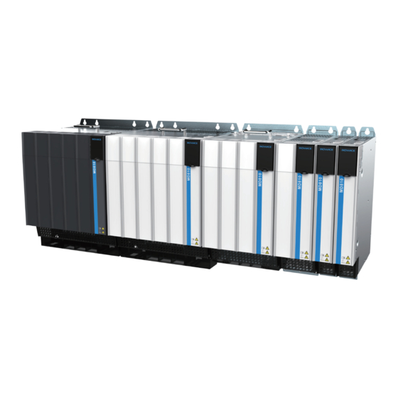
Standard drive multidrive system
Hide thumbs
Also See for MD810 Series:
- User manual (155 pages) ,
- User manual (254 pages) ,
- Installation manual (60 pages)
Table of Contents
Advertisement
Quick Links
Advertisement
Chapters
Table of Contents

Related Manuals for Inovance MD810 Series


Summary of Contents for Inovance MD810 Series
-
Page 2: Preface
Preface About This Guide The MD810 series is a new‑generation low‑voltage multidrive system. It is also a common DC bus drive system consisting of the power supply unit and the drive unit, which can meet requirements of a single mechanical device with multiple drive points and continuous production line system. -
Page 3: How To Obtain
This guide is not delivered with the product. You can obtain the PDF version by the following method: http://en.inovance.cn/ Log in to Inovance's website ( ), choose Support > Download, search by keyword, and then download the PDF file. ‑... -
Page 4: Table Of Contents
Table of Contents T T a a b b l l e e o o f f C C o o n n t t e e n n t t s s Preface ................1 Fundamental Safety Instructions . - Page 5 3.9.3 Wiring Sin‑Cos Encoders ..........130 3.9.4 Wiring Inovance 23‑Bit Communication Encoders ......131 3.9.5 Wiring SSI Encoders .
- Page 6 Table of Contents 3.11.4 Grounding the Cabinet System ..........143 4 Option Selection.
-
Page 7: Fundamental Safety Instructions
3. Use this equipment according to the designated environment requirements. Damage caused by improper use is not covered by warranty. 4. Inovance shall take no responsibility for any personal injuries or property damage caused by improper usage. Safety Levels and Definitions Indicates that failure to comply with the notice will result in death or severe personal injuries. - Page 8 Fundamental Safety Instructions Check whether the packing is intact and whether there is damage, water seepage, ● dampness, and deformation before unpacking. Unpack the package by following the unpacking sequence. Do not strike the package ● violently. Check whether there is damage, rust, or injuries on the surface of the equipment and ●...
- Page 9 Fundamental Safety Instructions Read through the guide and safety instructions before installation. ● Do not install this equipment in places with strong electric or magnetic fields. ● Before installation, check that the mechanical strength of the installation site can bear ●...
- Page 10 Fundamental Safety Instructions Do not connect the input power supply to the output end of the equipment. Failure to ● comply will result in equipment damage or even a fire. When connecting a drive to the motor, check that the phase sequences of the drive and ●...
- Page 11 Fundamental Safety Instructions Do not touch the equipment casing, fan, or resistor with bare hands to feel the ● temperature. Failure to comply may result in personal injuries. Prevent metal or other objects from falling into the equipment during operation. Failure ●...
-
Page 12: Safety Labels
Fundamental Safety Instructions Disposal Dispose of retired equipment in accordance with local regulations and standards. ● Failure to comply may result in property damage, personal injuries, or even death. Recycle retired equipment by observing industry waste disposal standards to avoid ●... -
Page 13: Product Information
Product Information Product Information Nameplate and Model 1.1.1 Power Supply Unit Nameplate and Model MODEL MD810-20M4T45G000 INPUT 3PH AC 380-480V 89.0A 50/60Hz OUTPUT DC 537V-679V 107.0A 45kW XXXXXXXXXXXXXXXX Suzhou Inovance Technology Co.,Ltd. Figure 1‑1 Power supply unit nameplate ‑ ‑... -
Page 14: Drive Unit Nameplate And Model
Product Information Figure 1‑2 Power supply unit model 1.1.2 Drive Unit Nameplate and Model Figure 1‑3 Drive unit nameplate ‑13‑... -
Page 15: Product Model List
Product Information Figure 1‑4 Drive unit model Product Model List Component Structure Power Width Model 50 mm 22 kW MD810‑20M4T22GXXX 100 mm MD810‑20M4T45GXXX 45 kW Booksize Power 200 mm MD810‑20M4T110GXXX 110 kW supply unit MD810‑20M4T160GXXX (W) 300 mm 160 kW Vertical MD810‑20M4T355G000 180 mm... -
Page 16: Technical Specifications
Product Information Component Structure Width Power Model MD810‑50M4T37GXXX (W) MD810‑50M4T45GXXX 200 mm MD810‑50M4T55GXXX 45–75 kW MD810‑50M4T75GXXX MD810‑50M4T90GXXX MD810‑50M4T110GXXX 300 mm 90–160 kW MD810‑50M4T132GXXX MD810‑50M4T160GXXX MD810‑50M4T200G200H MD810‑50M4T200G210H MD810‑50M4T250G200H MD810‑50M4T250G210H Vertical 230 mm 200–355 kW tower MD810‑50M4T315G200H MD810‑50M4T315G210H MD810‑50M4T355G200H MD810‑50M4T355G210H MD810‑50M4TD1.5GXXX MD810‑50M4TD2.2GXXX 50 mm 1.5–5.5 kW MD810‑50M4TD3.7GXXX... - Page 17 Product Information Power Output Rated Power Input Current Thermal Power Supply Unit Model Capacity Current DC Braking Unit (kW) AC (A) Power (W) (kVA) Three‑phase 380‑480 V, 50 Hz/60 Hz (47‑63 Hz) Optional MD810‑20M4T110GXXX external MDBUN series Optional MD810‑ external MDBUN 20M4T160GXXX(W) series Optional...
-
Page 18: Technical Specifications Of The Drive Unit
Product Information Specification Item ≤ 1000 m (3281 ft): derating not required > 1000 m (3281 ft): derated by 1% for every additional 100 m (328.1 ft) Protection for overtemperature, power phase loss, unbalance detection of three‑phase input voltage, Protection overvoltage, braking circuit overcurrent, braking resistor short circuit, and braking transistor direct functions connection detection... - Page 19 Product Information Output Applicable Motor Input Current Thermal Loss Rated Power current Drive Unit Model DC (A) AC (A) 537‑679 VDC (operating range: 350‑800 VDC); output voltage: 0‑480 VAC MD810‑ 5109 50M4T250GXXXH MD810‑ 6143 50M4T315GXXXH MD810‑ 7912 50M4T355GXXXH Table 1–4 Technical specifications of the drive unit (dual‑axis) Output Applicable Motor Input Current...
- Page 20 Product Information Specification Item V/f control: 0.8‑12 kHz Carrier frequency SVC and FVC: 2‑6 kHz The carrier frequency is automatically adjusted based on heatsink temperature. VF/f control: 0‑600 Hz Output frequency SVC and FVC: 0‑600 Hz Braking The braking module and braking resistor are used for braking. Three‑phase asynchronous motor: V/f control, SVC, and FVC Motor type and Permanent magnet synchronous motor (PMSM): SVC and FVC...
- Page 21 Product Information Specification Item 8 frequency sources, including the digital setting, voltage type analog setting, current type analog setting, pulse setting, communication setting, PID, multi‑speed, Frequency source and built‑in simple PLC The sources can be switched or superposed in various ways. Various triangular wave frequency control functions are provided.
-
Page 22: Components
Product Information Specification Item Protection for short circuit to ground upon power‑on, phase‑to‑phase short circuit, motor overheating (PT100, PT1000), drive overcurrent, drive overload (output power limit), motor overload, drive Protection overvoltage, drive undervoltage, drive SVC stall, drive overheating, output phase loss, communication functions fault, current detection fault, motor auto‑tuning fault, encoder fault detection, EEPROM read and write fault, buffer relay fault, locked‑rotor, excessive speed deviation, and stall alarm. -
Page 23: Components Of The Drive Unit
Product Information 1.4.2 Components of the Drive Unit The following figure shows the components of the drive unit (single‑axis). Different drive units (single‑axis) have different control circuit terminals. For details, see " 3.5.2.2 Layout of Control Circuit Terminals for the Drive Unit (Single‑Axis) " on page 76 Figure 1‑6 Components of the drive unit (single‑axis) The following figure shows the components of the drive unit (dual‑axis). - Page 24 Product Information Figure 1‑7 Components of the drive unit (dual‑axis) ‑23‑...
-
Page 25: System Architecture
Product Information System Architecture Figure 1‑8 System architecture Table 1–6 Function description of peripheral components for the MD810 series Compo Installation Function Description nent Position Name Between the power supply It is the circuit breaker for protection against short circuit. - Page 26 For the power supply unit with the power rating of 110 kW Power supply or above, use the braking unit (MDBUN) of Inovance and Braking unit with the the recommended braking resistor. unit power rating of...
-
Page 27: List Of Options
Product Information Compo Installation Function Description nent Position Name Between the With the DC soft charge unit, you can replace the drive unit DC soft power supply without powering off the power supply unit (bus voltage charge unit and the drive keeps normal). - Page 28 Product Information Applicable Unit Name Model Code 7.5‑18.5 kW (dual‑axis) ● Power supply unit: 110 kW MD810‑AZJ20M‑W3 1040042 Through‑hole mounting bracket with Drive unit: MD810‑AZJ50M‑W3 1040041 the width of 200 mm 45‑75 kW (single‑axis) Power supply unit: 160 kW Through‑hole Drive unit: mounting bracket with MD810‑AZJ20M‑W4...
- Page 29 Product Information Applicable Unit Name Model Code Drive unit: INOV‑SU‑60 (width of 100 11‑22 kW (single‑axis) 1040056 7.5‑11 kW (dual‑axis) Drive unit: INOV‑SU‑100 (width of 100 30‑37 kW (single‑axis) 1040025 15‑18.5 kW (dual‑axis) INOV‑SU‑170 (width of 200 Drive unit (single‑axis): 1040026 45‑75 kW MDBUN‑60‑T...
-
Page 30: System Selection
Product Information Applicable Unit Name Model Code Applicable to the model with 800 mm network cable C45590‑GNCN‑C2500080 1040016 the width of 180 mm System Selection 1.7.1 System Selection Flow Figure 1‑9 System selection flow ‑29‑... -
Page 31: Load And Motor Selection
Product Information 1.7.2 Load and Motor Selection 1. Determine the motor type and quantity according to the load and operating mode of the mechanical equipment. 2. Determine the requirements of the mechanical equipment for the power, torque, speed, startup, speed regulation, braking, overload, heating, and temperature rise of the motor. -
Page 32: System Combination And Arrangement
" 4.7 Braking Component " on page 151 ● 1.7.5 System Combination and Arrangement The MD810 series supports single‑rack or dual‑rack installation, and the power supply unit can be installed in the middle or on the left side. Single-rack installation If the cabinet has enough space, it is recommended to install units on a single rack, with the power supply unit placed on the left or in the middle. - Page 33 Product Information Arrangement Mode Example Bus Current Calculation I power supply unit ≥ 80% x (I 1 + I 2 + I 3 Power supply unit + I 4 + I 5 + I 6 + ...) placed on the left I 1 + I 2 + I 3 + I 4 + I 5 + I 6 + ...
- Page 34 Product Information Schematic Diagram of Combination and Arrangement Mode Bus Current Calculation Arrangement I power supply unit ≥ 80% x (I 1 + I 2 + I 3 + I 4 + One power supply I 5 + I 6 + ...) unit I 1 + I 2 + ...
-
Page 35: Mechanical Design
Mechanical Design Mechanical Design Layout and Dimension 2.1.1 Layout and Dimension of the Power Supply Unit The power supply unit can be classified into the booksize unit with equal width and height and the vertical tower unit. The booksize drive unit has the width of 50 mm, 100 mm, 200 mm, and 300 mm, and the vertical tower drive unit has the width of 180 mm. -
Page 36: Layout And Dimension Of The Drive Unit (Single-Axis)
Mechanical Design Dimension (mm) Mounting Hole (mm) Mount ing Hole Weight Power Supply Unit Size (kg) Model (mm) MD810‑ ‑ Φ7 20M4T110GXXX MD810‑ Φ7 20M4T160GXXX MD810‑ 426.5 Φ7 20M4T160GXXXW MD810‑ φ12 ‑ 20M4T355GXXX 2.1.2 Layout and Dimension of the Drive Unit (Single-Axis) The drive unit (single‑axis) can be classified into the booksize unit with equal width and height and the vertical tower unit. - Page 37 Mechanical Design Figure 2‑2 Layout and dimension of the drive unit (single‑axis) Table 2–1 Layout and dimension of the drive unit (single‑axis) Mounting Hole (mm) Mount Dimension (mm) Weight ing Hole Drive Model Size (kg) (mm) MD810‑50M4T1.5GXXX ‑ ‑ Φ7 MD810‑50M4T2.2GXXX ‑...
-
Page 38: Layout And Dimension Of The Drive Unit (Dual-Axis)
Mechanical Design Dimension (mm) Mounting Hole (mm) Mount ing Hole Weight Drive Model Size (kg) (mm) MD810‑50M4T30GXXX ‑ Φ7 MD810‑50M4T37GXXX ‑ Φ7 MD810‑50M4T45GXXX ‑ Φ7 18.4 MD810‑50M4T55GXXX ‑ Φ7 18.4 MD810‑50M4T75GXXX ‑ Φ7 19.5 MD810‑50M4T90GXXX Φ7 24.2 MD810‑50M4T110GXXX Φ7 24.2 MD810‑50M4T132GXXX Φ7 25.2... - Page 39 Mechanical Design Figure 2‑3 Layout and dimension of the drive unit (dual‑axis) Table 2–2 Layout and dimension of the drive unit (dual‑axis) Mounting Hole (mm) Mount Dimension (mm) ing Hole Weight Drive Model (kg) Diameter (mm) MD810‑ ‑ ‑ Φ7 50M4TD1.5GXXX MD810‑...
-
Page 40: Cabinet Design
Cabinet Design 2.2.1 Clearance Requirements The power supply unit and drive unit of the MD810 series are classified into booksize and vertical tower structures. The booksize unit features the width of 50 mm, 100 mm, 200 mm, and 300 mm, and the vertical tower unit features the width of 180 mm (power supply unit only) and 230 mm (drive unit only). - Page 41 Mechanical Design Figure 2‑4 Clearances for installing the booksize unit in dual‑rack mode ‑ ‑...
-
Page 42: Mounting Backplate Design Requirements
Mechanical Design Figure 2‑5 Clearances for installing the vertical tower unit Note It is recommend that the power supply unit and drive unit be installed vertically. 2.2.2 Mounting Backplate Design Requirements Thickness and stiffness reinforcement principles To avoid damage to the unit during transportation and ensure its normal operation, the mounting backplate of the unit must feature excellent stiffness and strength performance and a thickness of not less than 2 mm. - Page 43 Mechanical Design Scheme 2: Welding a lateral reinforced beam on the back of the backplate ● Mounting hole principles The booksize unit is characterized by equal height and equal spacing of mounting ● holes of 50 mm. Drill mounting holes on the backplate in advance for convenient installation.
-
Page 44: Mounting Hole Dimensions
Mechanical Design Mounting hole dimensions Dimensions of mounting holes for the booksize units ● Dimensions of mounting holes for the vertical tower units ● ‑43‑... -
Page 45: Cabinet Cooling Design
Mechanical Design 2.2.3 Cabinet Cooling Design Cabinet door cooling design The unit is forcedly air cooled with a built‑in fan. To ensure that enough cooling air enters the cabinet, the air inlet on the cabinet door must be large enough. The air flows from bottom to top after being heated. - Page 46 Mechanical Design Table 2–4 Minimum effective ventilation area of the cabinet air inlet for the power supply unit Minimum Effective Ventilation Area of the Cabinet Power Supply Unit Model Air Inlet (cm MD810‑20M4T22GXXX MD810‑20M4T45GXXX MD810‑20M4T110GXXX MD810‑20M4T160GXXX (W) MD810‑20M4T355GXXX Table 2–5 Minimum effective ventilation area of the cabinet air inlet for the drive unit Minimum Effective Ventilation Area of the Cabinet Drive Unit model Air Inlet (cm...
- Page 47 Mechanical Design Minimum Effective Ventilation Area of the Cabinet Drive Unit model Air Inlet (cm MD810‑50M4TD15GXXX (W) MD810‑50M4TD18.5GXXX(W) Note The preceding table applies only to one single unit in the cabinet. When multiple ● units are installed in the cabinet, the total required ventilation area is the sum of all the above‑mentioned ventilation areas.
- Page 48 Mechanical Design Figure 2‑7 Backflow of hot air in the cabinet in passive air ventilation mode (without any isolating device) Therefore, in passive air ventilation, use an isolating device in the cabinet to prevent backflow of hot air. An isolating device can be a plate or exhaust duct. Figure 2‑8 Backflow of hot air in the cabinet in passive air ventilation mode (with an iso‑...
- Page 49 Mechanical Design that hot air can be exhausted to the outside of the cabinet, the minimum effective ventilation areas of the cabinet air outlet must meet the following requirements when passive air ventilation is used. Table 2–6 Minimum effective ventilation area of the cabinet air inlet for the power supply unit Minimum Effective Ventilation Area of the Cabinet Power Supply Unit Model...
- Page 50 Mechanical Design Minimum Effective Ventilation Area of the Cabinet Drive Unit Model Air Outlet (cm MD810‑50M4TD15GXXX MD810‑50M4TD18.5GXXX Note " Table 2–6 " on page 48 " Table 2–7 " on page 48 apply only to one single unit ● in the cabinet. When multiple units are installed in the cabinet, the total required ventilation area is the sum of all the above‑mentioned ventilation areas.
- Page 51 Mechanical Design Note When installing the fan, ensure that the hot air can be exhausted from the cabinet ● to outside, avoiding the overheating of or damage to the power supply unit or the drive unit. The distance between the top cover of the air outlet and the fan outlet must be at ●...
- Page 52 Mechanical Design Cooling Air Volume (CFM) Drive Unit Model MD810‑50M4T315GXXXH MD810‑50M4T355GXXXH MD810‑50M4TD1.5GXXX MD810‑50M4TD2.2GXXX MD810‑50M4TD3.7GXXX MD810‑50M4TD5.5GXXX MD810‑50M4TD7.5GXXX MD810‑50M4TD11GXXX MD810‑50M4TD15GXXX MD810‑50M4TD18.5GXXX Note: 1 CFM = 0.02832 m /min Cabinet fan selection To select a cabinet fan, do as follows: 1. Calculate the cooling air volume required for all drive units according to "...
- Page 53 Mechanical Design Figure 2‑10 Q of a system fan ‑ ‑...
-
Page 54: Electrical Design
Electrical Design Electrical Design Electrical Wiring If a drive unit fails, you need to power off the faulty drive unit and the power supply unit, replace with a new drive unit, and then power on the power supply unit and the new drive unit. - Page 55 Electrical Design Figure 3‑2 Electrical connection ‑ ‑...
-
Page 56: Layout And Description Of Main Circuit Terminals
Electrical Design Layout and Description of Main Circuit Terminals 3.2.1 Layout and Description of Main Circuit Terminals for the Power Sup- ply Unit Figure 3‑3 Layout and dimensions (mm) of main circuit terminals for the booksize power supply unit ‑55‑... - Page 57 Electrical Design Figure 3‑4 Layout and dimensions (mm) of main circuit terminals for the vertical tower power supply unit Table 3–1 Descriptions of main circuit terminals Name Description Mark R, S, T Three‑phase AC input input Used to connect the three‑ terminals phase AC input power supply.
-
Page 58: Layout And Description Of Main Circuit Terminals For The Drive Unit (Single-Axis)
Electrical Design 3.2.2 Layout and Description of Main Circuit Terminals for the Drive Unit (Single-Axis) Figure 3‑5 Layout and dimensions (mm) of main circuit terminals for the booksize drive unit (single‑axis) ‑57‑... - Page 59 Electrical Design Figure 3‑6 Layout and dimensions (mm) of main circuit terminals for the vertical tower drive unit (single‑axis) Table 3–2 Descriptions of main circuit terminals Name Mark Description U, V, W Three‑phase AC output Used to connect a three‑ terminals phase motor.
-
Page 60: Layout And Description Of Main Circuit Terminals For The Drive Unit (Dual-Axis)
Electrical Design 3.2.3 Layout and Description of Main Circuit Terminals for the Drive Unit (Dual-Axis) Figure 3‑7 Layout and dimensions of main circuit terminals Table 3–3 Descriptions of main circuit terminals Name Description Mark U1, V1, W1 Three‑phase AC output Used to connect a three‑... -
Page 61: Wiring Descriptions Of Main Circuit Terminals
Electrical Design Wiring Descriptions of Main Circuit Terminals Three-phase AC input terminals R, S, and T (power supply unit input side) The cable connection on the input side of the power supply unit has no ● requirements on the phase sequence. The specifications and installation method of external power cables must comply ●... - Page 62 Electrical Design power cable fixing bracket to connect the shield in 360°, and crimp the shield drain wire to the PE terminal. Figure 3‑8 Installation of the shield bracket Keep the shield drain wire of the motor cable as short as possible, and ensure that ●...
- Page 63 Electrical Design Note The external 24 V power supply provides each unit with current of 1 A. ● The external 24 V power supply is optional without affecting normal use of the ● unit. Braking resistor connection terminals BR and P For the selection of braking resistors, refer to the recommended value and keep ●...
-
Page 64: Cable Selection For Main Circuits
Electrical Design Figure 3‑10 Protective grounding connection of main circuit terminals VDR and EMC grounding jumper The drive is applicable to power grid systems with neutral grounding. If the drive is ● used in IT power system (where the neutral point is not grounded), remove the VDR and EMC grounding jumpers. - Page 65 Electrical Design PE cable. To suppress radio frequency interference effectively, use the coaxial copper braid as the cable shield. Ensure that the braided density is greater than 90% to enhance the shielding performance and conductivity. Figure 3‑12 Recommended main circuit cable types Specifications for main circuit cables Table 3–4 Cable specifications and tightening torque of main circuit cables of the power supply unit Input Terminals R, S, and T...
- Page 66 Electrical Design Output Terminals (U, V, W) Grounding Terminal PE Recommended Recommend Tightening Tightening Drive Unit Model IEC Cable ed IEC Cable Screw Screw Torque Torque Specification Specification N·m N·m MD810‑ 50M4T7.5GXXX MD810‑ 50M4T11GXXX(W) MD810‑ 50M4T15GXXX(W) MD810‑ 50M4T18.5GXXX(W) MD810‑ 50M4T22GXXX(W) MD810‑...
- Page 67 Electrical Design Output Terminals (U, V, W) Grounding Terminal PE Recommended Recommend Tightening Tightening Drive Unit Model IEC Cable ed IEC Cable Screw Screw Torque Torque Specification Specification N·m N·m MD810‑ 50M4TD5.5GXXX MD810‑ 50M4TD7.5GXXX( MD810‑ 50M4TD11GXXX(W) MD810‑ 50M4TD15GXXX(W) MD810‑ 50M4TD18.5GXXX( Recommended cable lug The cable lugs manufactured by Suzhou Yuanli are recommended, as shown below.
-
Page 68: Layout And Description Of Control Circuit Terminals
Electrical Design Layout and Description of Control Circuit Terminals 3.5.1 Layout and Description of Control Circuit Termi- nals for the Power Supply Unit 3.5.1.1 Relationship Between Power Supply Unit Models and Control Circuit Terminals Power Supply Unit Model (MD810‑20M4TXXGXXX) Terminal Terminal Terminal Mark Terminal Name... -
Page 69: Layout Of Control Circuit Terminals For The Power Supply Unit
Electrical Design Note "One" indicates that the model has one terminal of this type. "‑" indicates that the model does not have the terminal of this type. 3.5.1.2 Layout of Control Circuit Terminals for the Power Supply Unit Figure 3‑13 Control circuit terminals of MD810‑20M4TXXG000 and MD810‑20M4TXXG100 ‑... - Page 70 Electrical Design Figure 3‑14 Control circuit terminals of MD810‑20M4TXXG010 and MD810‑20M4TXXG110 Figure 3‑15 Control circuit terminals of MD810‑20M4TXXG020 and MD810‑20M4TXXG120 ‑69‑...
-
Page 71: Descriptions Of Control Circuit Terminals For The Power Supply Unit
Electrical Design 3.5.1.3 Descriptions of Control Circuit Terminals for the Power Supply Unit Table 3–6 CAN1 communication terminal CN1 Specification Pin Mark Pin Definition CAN_H signal of CAN CAN1H communication CANopen/CANlink is supported. CAN_L signal of CAN The external terminal of CAN1 is CAN1L communication used for communication with the... - Page 72 Electrical Design Table 3–9 Relay terminal CN4 Specification Pin Mark Pin Definition TA‑TB: Normally closed Contact capacity: 250 VAC/3 A TA/TB/TC TA‑TC: Normally open (Cosφ = 0.4) Table 3–10 PROFIBUS DP communication terminal DB9 Specification Pin Mark Pin Definition Unconnected Unconnected PROFIBUS DP bus positive end Unconnected...
- Page 73 Electrical Design Specification Pin Mark Pin Definition CAN_H signal of CAN CANopen/ CAN1H communication CANlink supported; CAN_L signal of CAN CAN1L used for communication communication with the host Communication signal controller and CGND ground internal commissioning RS485 positive Internal bus, RS485+ communication signal used only for...
- Page 74 Electrical Design Table 3–13 DIP switch S1 Description DIP Switch Position 1 and 2 set to ON: Termination RS485 termination resistor enabled resistor (during RS485 communication through terminals 1 and 2 set to OFF: RJ45A/RJ45B) Termination resistor disabled 3 and 4 set to ON: Termination CAN1 termination resistor enabled resistor...
-
Page 75: Layout And Description Of Control Circuit Terminals For The Drive Unit (Single-Axis)
Electrical Design 3.5.2 Layout and Description of Control Circuit Termi- nals for the Drive Unit (Single-Axis) 3.5.2.1 Relationship Between Drive Unit (Single Axis) Models and Control Circuit Terminals Drive Unit Model (MD810‑50M4TXXGXXX) Termi Termi Termi Termi Defini G200 G201 G210 G211 G300 G400... - Page 76 Electrical Design Drive Unit Model (MD810‑50M4TXXGXXX) Termi Termi Termi Termi Defini G200 G201 G210 G211 G300 G400 G530 G531 Type Code Name tion termi on page Resolv " Table None 3–23 " (DB15 encod ‑ ‑ ‑ ‑ ‑ ‑ ‑...
-
Page 77: Layout Of Control Circuit Terminals For The Drive Unit (Single-Axis)
Electrical Design Drive Unit Model (MD810‑50M4TXXGXXX) Termi Termi Termi Termi Defini G200 G201 G210 G211 G300 G400 G530 G531 Type Code Name tion Drive Unit Model (MD810‑50M4TXXGXXX) ‑ ‑ G200 G201 G210 G211 G300 G400 G530 G531 " Figure " Figure "... - Page 78 Electrical Design Figure 3‑17 MD810‑50M4TXXG201 control circuit terminals Figure 3‑18 MD810‑50M4TXXG210 control circuit terminals ‑77‑...
- Page 79 Electrical Design Figure 3‑19 MD810‑50M4TXXG211 control circuit terminals Figure 3‑20 MD810‑50M4TXXG300 control circuit terminals ‑ ‑...
- Page 80 Electrical Design Figure 3‑21 MD810‑50M4TXXG400 control circuit terminals Figure 3‑22 MD810‑50M4TXXG530 control circuit terminals ‑79‑...
-
Page 81: Descriptions Of Control Circuit Terminals For The Drive Unit (Single-Axis)
Electrical Design Figure 3‑23 MD810‑50M4TXXG531 control terminals 3.5.2.3 Descriptions of Control Circuit Terminals for the Drive Unit (Single-Axis) Table 3–15 DI/DO terminals (CN1) Specification Pin Mark Pin Definition Common multi‑function Isolated sink/source input programmable DI1‑DI2 input terminal terminal; input frequency: < 100 Hz Isolated programmable I/O terminal;... - Page 82 Electrical Design Table 3–16 AI/AO terminals (CN2) Specification Pin Mark Pin Definition 0 V to 10 V and ‑10 V to +10 V available; 12‑ bit resolution, correction accuracy error: ±3%; input impedance: 22.1 k Analog input channel AI1 Temperature sensors PT100 and PT1000 (switched over by sub‑switch 3 of DIP switch S1) are supported.
- Page 83 Electrical Design Table 3–18 External CAN2/RS485 communication terminal (CN4) Specification Pin Mark Pin Definition External RS485 communication C485+ Used to communicate with the host positive signal controller (such as PLC) based on External RS485 communication RS485 C485‑ negative signal CAN_H signal of CAN CAN2H As the CAN communication internal communication...
- Page 84 Electrical Design Table 3–22 23‑bit encoder terminal (DB9) Specification Pin Mark Pin Definition Bus communication signal+ Bus communication signal‑ PS‑ Unconnected ‑ Unconnected ‑ Unconnected ‑ Unconnected ‑ Encoder +5 V power supply Encoder +5 V power supply ground Note that when the DB9 terminal is used as the 23‑bit encoder terminal, Unconnected ‑...
- Page 85 Power supply ground for encoders The multi‑encoder terminal can be Communication positive signal or used to connect the 5 V differential PS+/DATA+ SSI data positive signal for Inovance ABZ, 23‑bit communication, sine‑ 23‑bit encoders cosine, and SSI encoders, and Communication negative signal or supports incremental frequency PS‑/DATA‑...
- Page 86 Electrical Design Table 3–25 RJ45 communication terminals RJ45A/ RJ45B Specification Pin Mark Pin Definition CANopen/ CAN_H signal of CAN CAN1H communication CANlink supported; CAN_L signal of CAN CAN1L used for communication communica tion with the Communication signal host controller CGND ground and internal commissioning...
- Page 87 Electrical Design Table 3–26 EtherCAT communication terminals ECT‑IN and ECT‑OUT Specification Pin Mark Pin Definition Data transmitting+ The yellow indicator indicates that the link Data transmitting‑ TX‑ has been established. Data receiving+ The green indicator indicates that the Data receiving– RX‑...
-
Page 88: Layout And Description Of Control Circuit Terminals For The Drive Unit (Dual-Axis)
Electrical Design Description Terminal Name DIP Switch Position 3 set to ON: Termination CAN2 termination resistor resistor enabled (during CAN communication through external CAN2/RS485 communication terminals 3 set to OFF: Termination marked by CN4) resistor disabled 4 set to ON: 5 V power supply output Power supply for the ABZ encoder terminal... - Page 89 Electrical Design Termi Drive Unit Model (MD810‑50M4TDXXGXXX) Terminal Terminal Terminal Code Name Definition G200 G201 G210 G211 G300 Type PROFIBUS None " Table 3–34 (DB9 communica ‑ ‑ ‑ " on page 95 terminal) tion terminal encoder ‑ terminal for "...
-
Page 90: Layout Of Control Circuit Terminals For The Drive Unit (Dual-Axis)
Electrical Design Note "One" indicates that the model has one terminal of this type. ● "Two" indicates that the model has two terminals of this type. ● "‑" indicates that the model does not have the terminal of this type. ●... - Page 91 Electrical Design Figure 3‑25 MD810‑50M4TDXXG201 control circuit terminals Figure 3‑26 MD810‑50M4TDXXG210 control circuit terminals ‑ ‑...
- Page 92 Electrical Design Figure 3‑27 MD810‑50M4TDXXG211 control circuit terminals ‑91‑...
-
Page 93: Descriptions Of Control Circuit Terminals For The Drive Unit (Dual-Axis)
Electrical Design Figure 3‑28 MD810‑50M4TDXXG300 control circuit terminals 3.5.3.3 Descriptions of Control Circuit Terminals for the Drive Unit (Dual-Axis) Table 3–29 Common terminal and axis 1 analog/digital I/O terminal (CN1) Specification Pin Mark Pin Definition 24 V ± 10%; no‑load voltage: ≤ 30 V; Internal 24 V power maximum output current: 200 mA;... - Page 94 Electrical Design Specification Pin Mark Pin Definition accuracy error: ±3%; input impedance in voltage mode: 22.1 k; input impedance in current mode: 250 Ω or 500 Ω Temperature sensors PT100 and PT1000 (F9‑56) are supported. Common multi‑function Isolated sink/source input programmable terminal;...
- Page 95 Electrical Design Table 3–31 Axis 2 analog/digital I/O terminal (CN3) Specification Pin Mark Pin Definition 0 V to 10 V, ‑10 V to +10 V, and 0 mA to 20 mA available; 12‑bit resolution, correction accuracy error: ±3%; input impedance in Analog input channel AI1 voltage mode: 22.1 k;...
- Page 96 Electrical Design Table 3–34 PROFIBUS DP communication terminal (DB9 terminal) Specification Pin Mark Pin Definition Unconnected ‑ Unconnected ‑ PROFIBUS DP bus positive end Unconnected ‑ PROFIBUS DP bus power supply CGND2 ground PROFIBUS DP bus power supply Unconnected ‑ PROFIBUS DP bus negative end TR‑...
- Page 97 Electrical Design Specification Pin Mark Pin Definition RS485 positive RS485+ communication signal RS485 negative Internal bus, RS485‑ communication signal used only for the external Unconnect ‑ operating panel and PC Unconnect ‑ commissioning Communication signal CGND ground CAN_H signal of CAN CANopen/ CAN1H communication...
- Page 98 Electrical Design Specification Pin Mark Pin Definition STO channel 2 power supply 2GND negative Table 3–38 DIP switch S1 Description Terminal Name DIP Switch Position 1 and 2 set to ON: Termination resistor CAN1 termination resistor enabled (during CAN communication through terminals RJ45A/ RJ45B) 1 and 2 set to OFF:...
-
Page 99: Cable Selection And Wiring Requirements For Control Circuits
Electrical Design Cable Selection and Wiring Requirements for Control Circuits Control circuit cable selection All control cables must be shielded cables. ● It is recommended that digital signal cables use shielded twisted pair (STP) cables. ● Figure 3‑29 STP Control circuit wiring Lay the motor cable far from all control circuit cables. -
Page 100: I/O Signal Terminal Wiring
Electrical Design I/O Signal Terminal Wiring 3.7.1 Wiring the DI The DI can be wired in the sink (NPN) and source (PNP) mode. Sink wiring mode Figure 3‑31 Sink wiring mode To use the internal 24 V power supply of the drive, which is the most commonly ●... -
Page 101: Wiring The Dio1 And Dio2
Electrical Design Figure 3‑32 Parallel connection of DI terminals of multiple drives in the sink mode Source wiring mode Figure 3‑33 Source wiring mode To use the internal 24 V power supply of the drive, remove the jumper on the +24V ●... -
Page 102: Wiring The Ai
Electrical Design DIO1 and DIO2 can be used as either the DI or the DO at the same time. When DIO1 and DIO2 are used as the DI, the wiring method is the same as that of ● DI1 and DI2. When DIO1 and DIO2 are used as the DO, the DO common terminal is COM and ●... - Page 103 Electrical Design Figure 3‑35 Wiring when AI1 used for analog input Figure 3‑36 Wiring when AI1 used for temperature sensor input Connect the drain wire of the AI shield to the PE terminal on the drive side. ‑ ‑...
- Page 104 Electrical Design Figure 3‑37 Grounding of the AI shield Wiring AI2 AI2 supports 0 V to 10 V input and 0 mA to 20 mA input. When F4‑40 is set to 0, AI2 adopts the voltage input mode. The wiring description ●...
-
Page 105: Wiring The Ao
Electrical Design Figure 3‑38 Wiring AI2 3.7.4 Wiring the AO The AO supports 0 V to 10 V and 0 mA to 20 mA output, which can be selected by F5‑ 23 (AO mode selection). When the AO adopts the voltage output mode, set F5‑23 to 0. In this case, the load ●... - Page 106 Electrical Design When a contactor and an intermediate relay are connected to 220 VAC, parallel a ● VDR with a withstand voltage higher than 275 VAC at both ends of the drive coil of the contactor and the intermediate relay. When a contactor and an intermediate relay are connected to 24 VDC, inversely ●...
-
Page 107: Communication Connection
Electrical Design Communication Connection 3.8.1 RS485 Communication Connection Product models and communication terminals The power supply unit and the drive unit communicate with the PLC through the external CAN2/RS485 communication terminals (CN2 for the power supply unit and CN4 or CN6 for the drive unit). The following table describes the power supply unit models and the drive unit models that can communicate with the PLC based on the RS485 protocol and the communication terminals. -
Page 108: Network Topology
Electrical Design Note "One" indicates that the model has one terminal of this type. ● "‑" indicates that the model does not have the terminal of this type. ● Network topology The power supply unit and the drive unit communicate with the PLC through the ●... -
Page 109: Transmission Distance
Electrical Design Transmission distance The following table describes the maximum number of nodes and the maximum transmission distance supported at different baud rates. Transmission Baud Rate Number of Nodes Cross‑sectional Area Distance (m) (kbps) of Cable 1000 19.2 AWG26 Without repeater: < 32; with repeater: 128 at most 115.2 AWG26... -
Page 110: Can Communication Connection
3.8.2 CAN Communication Connection Product models and communication terminals For the MD810 series drive, only the power supply unit can communicate with the PLC based on the CAN protocol, and the drive unit receives control signals of the PLC through the power supply unit. - Page 111 Electrical Design Power Supply Unit Model (MD810‑20M4TXXGXXX) Terminal Terminal Terminal Mark Name Definition G000, G100 G010, G110 G020, G120 CAN1 " Table 3–6 " on communi cation page 70 terminal Note "One" indicates that the model has one communication terminal of this type. Network topology CAN communication bus connection is described as follows: The power supply unit and the PLC communicate with each other through the CAN...
- Page 112 Electrical Design Figure 3‑42 CAN communication bus connection (with the power supply unit installed at the start or end of the CAN bus) If the power supply unit is in the middle of the CAN bus, do not connect to the PLC through the CAN connection terminal of the power supply unit.
- Page 113 Electrical Design Figure 3‑43 CAN communication bus connection (with the power supply unit installed at the middle of the CAN bus) Transmission distance The following table describes the maximum transmission distance supported at different baud rates. Baud Rate (bps) Length (m) 500 k 250 k 125 k...
- Page 114 Electrical Design Termination resistor Table 3–43 Settings of termination resistors for the power supply unit Terminal Description DIP Switch Position Mark 3 and 4 set to ON: CAN1 termination Termination resistor resistor enabled (during CAN switch communication through terminals 3 and 4 set to OFF: RJ45A/RJ45B) Termination resistor disabled...
-
Page 115: Profibus Dp And Profibus Dp-To-Can Communication Connection
Electrical Design 3 set to OFF: Termination resistor disabled Table 3–45 Settings of termination resistors for the drive unit (dual‑axis) Termi Description DIP Switch Position nal Mark 1 and 2 set to ON: CAN1 termination Termination resistor resistor enabled (during CAN switch communication through terminals... - Page 116 Electrical Design Power Supply Unit Model (MD810‑20M4TXXGXXX) Terminal Mark Terminal Name Terminal Definition G010, G110 G210 G211 PROFIBUS DP " Table 3–21 " on page None (DB9 terminal) communication terminal Drive Unit (Dual‑axis) Model (MD810‑ 50M4TDXXGXXX) Terminal Mark Terminal Name Terminal Definition G210 G211...
- Page 117 Electrical Design Figure 3‑44 PROFIBUS DP communication bus connection Network topology (PROFIBUS DP-to-CAN communication) When only the power supply unit supports PROFIBUS DP communication, the drive unit can receive control signals of the PLC through the power supply unit. Communication bus connection is described as follows: The power supply unit and the PLC communicate with each other through the ●...
-
Page 118: Profinet-To-Can Communication Connection
3.8.4 PROFINET-to-CAN Communication Connection Product models and communication terminals For the MD810 series drive, only the power supply unit can communicate with the PLC based on the PROFINET protocol, and the drive unit receives control signals of the PLC through the power supply unit. - Page 119 Electrical Design The power supply unit communicates with the PLC through PROFINET communication terminals ProfinetA and ProfinetB. The following table describes the power supply unit models that can communicate with the PLC based on the PROFINET protocol and the communication terminals. Power Supply Unit Model (MD810‑20M4TXXGXXX) Terminal Mark Terminal Name...
-
Page 120: Ethercat Communication Connection
3.8.5 EtherCAT Communication Connection Product models and communication terminals For the MD810 series drive, only the drive unit can communicate with the PLC based on the EtherCAT protocol, and the power supply unit receives control signals of the PLC through the drive unit. - Page 121 Electrical Design that can communicate with the PLC based on the EtherCAT protocol and the communication terminals. Drive Unit (Single‑axis) Model (MD810‑ 50M4TXXGXXX) Terminal Mark Terminal Name Terminal Definition G530 G531 EtherCAT " Table 3–26 " on page ECT‑IN/ECT‑OUT communication terminal Note "One"...
-
Page 122: Encoder Signal Connection
Electrical Design Encoder Signal Connection 3.9.1 Wiring ABZ Encoders 3.9.1.1 Encoder Terminals and Specifications Product models and encoder terminals The following table describes the drive unit models that support ABZ encoders and the encoder terminals. Drive Unit (Single‑axis) Model (MD810‑50M4TXXGXXX) Termi Termi Termi... -
Page 123: Encoder Specifications
Electrical Design Note "One" indicates that the model has one terminal of this type. ● "‑" indicates that the model does not have the terminal of this type. ● Encoder specifications Power supply 5 V/200 mA, 15 V/100 mA Maximum Input Differential: 500 kHz;... - Page 124 Electrical Design Figure 3‑49 Wiring the differential encoder through the ABZ encoder terminal Figure 3‑50 Wiring the differential encoder through the multi‑encoder terminal (DB15) ‑123‑...
- Page 125 Electrical Design Note The power supply of the differential ABZ encoder only supports 5 V. However, the ● ABZ encoder terminal supports the power supply of 5 V and 15 V. Therefore, before power‑on, set sub‑switch 4 of DIP switch S2 to ON to select 5 V output. Otherwise, the encoder will be damaged due to high power supply voltage.
-
Page 126: Collector Input Wiring
Electrical Design 3.9.1.3 Collector Input Wiring Collector input wiring 1 Due to the collector electrical characteristics, the rising edge of the signal is slow, and the signal transmission distance is limited. The collector input wiring method is suitable only for applications with the cable length shorter than 20 m and the frequency lower than 50 kHz. -
Page 127: Push-Pull Input Wiring
Electrical Design In the closed‑loop vector control mode, when the running frequency is greater ● than a certain value, the motor encounters abnormality. Collector encoder input wiring 2 procedure: 1. Connect the A, B, and Z output signal cables of the encoder to A+, B+, and Z+ of the ABZ encoder terminal, respectively. -
Page 128: Distinguishing Collector Output Encoders From Push-Pull Output Encoders
Electrical Design 2. Select the encoder power supply mode (5 V or 15 V) of the ABZ encoder terminal according to the encoder power supply voltage. Set sub‑switch 4 of the DIP switch S2 to ON to select 5 V power supply output, and to OFF to select 15 V power supply output. -
Page 129: Wiring Resolver Encoders
Electrical Design 3. Slowly turn the motor shaft. If the multimeter shows that the voltage changes, the encoder is a push‑pull output type; if the multimeter shows that the voltage keeps at 0 V, the encoder is a collector output type. 3.9.2 Wiring Resolver Encoders Product models and encoder terminals The following table describes the drive unit models that support resolver encoders... - Page 130 Electrical Design Shielded twisted pair (STP) cables are recommended. Connect one twisted pair cable to one pair of differential signal cables. Figure 3‑55 Wiring the resolver encoder When you need to use the incremental differential frequency division output function, connect the PLC or PG card to the resolver encoder terminal (DB15) of the drive, as shown in the following figure.
-
Page 131: Parameter Settings
Electrical Design Figure 3‑56 Wiring for incremental differential frequency division output Parameter settings Set F1‑28 (encoder type) to 3 (resolver encoder). Set F1‑29 to select the related filter mode. 3.9.3 Wiring Sin-Cos Encoders Product models and encoder terminals The following table describes the drive unit models that support sin‑cos encoders and the encoder terminals. -
Page 132: Wiring Inovance 23-Bit Communication Encoders
Set F1‑21 (sinusoid per revolution of sin‑cos encoder) according to the actual value of the encoder. 3.9.4 Wiring Inovance 23-Bit Communication Encoders Product models and encoder terminals The following table describes the drive unit models that support Inovance 23‑bit communication encoders and the encoder terminals. ‑131‑... - Page 133 Data refresh frequency 16 kHz Maximum RS485 4 Mbit/s communication speed Wiring description Connect the signal cable of the Inovance 23‑bit communication encoder to the 23‑bit encoder terminal (DB9) or multi‑encoder terminal (DB15) of the drive, as shown below. ‑ ‑...
-
Page 134: Wiring Ssi Encoders
Electrical Design Figure 3‑58 Wiring of Inovance 23‑bit communication encoders Parameter settings Encoder type settings: For drive unit (single‑axis) 530/531 models, set F1‑23 (PG2 encoder type) to 1 to ● select the 23‑bit encoder. For other drive units that support 23‑bit encoders, set F1‑28 (encoder type) to 1 to ●... - Page 135 Electrical Design Drive Unit (Single‑axis) Model (MD810‑ 50M4TXXGXXX) Terminal Mark Terminal Name Terminal Definition G530 G531 None (DB15 Multi‑encoder " Table 3–24 " on page 84 terminal) terminal Note "One" indicates that the model has one encoder terminal of this type. Encoder specifications Power Supply 5 V/300 mA, 12 V/200 mA...
- Page 136 Electrical Design Note Select the power supply voltage according to the encoder power supply. " Table 3–47 " on page 135 describes the relationship between the SSI baud rate and the ca‑ ble length. Table 3–47 Relationship between the SSI baud rate and the cable length Baud Rate (kbps) Cable Length (m) 1000...
-
Page 137: Incremental Frequency Division Output
Electrical Design 3.9.6 Incremental Frequency Division Output Product models and encoder terminals The following table describes the drive unit models that support incremental frequency division output the encoder terminals. Drive Unit (Single‑axis) Model (MD810‑50M4TXXGXXX) Terminal Mark Terminal Name Terminal Definition G530 G531 None (DB15... -
Page 138: Selecting Filter Modes
Electrical Design Figure 3‑60 Wiring for incremental frequency division output Parameter settings Set F1‑20 (frequency division signal source). If the frequency division signal is given by ABZ incremental encoder, set the ABZ incremental frequency division coefficient through F1‑35. Otherwise, set the frequency coefficient of the absolute encoders through F1‑46. -
Page 139: Wiring Sto Terminals
Electrical Design case, automatic interlocking is recommended, which enables the terminal to switch between the adaptive filtering mode and the fixed interlocking mode. This can better cope with the working conditions with both zero speed and non‑zero speed. 3.10 Wiring STO Terminals Product models and encoder terminals The following table describes the drive unit (single‑axis) models that support the STO function and the STO terminal. -
Page 140: Emc Requirements
Electrical Design Electrical specifications and connection of the input circuit The following table describes the relationship between the STO input status and the drive working status. STO1 Input Status STO2 Input Status Drive Working Status High Not running High High High Running The following table describes the electrical characteristics of the safety request input... -
Page 141: Other Requirements
Electrical Design The maximum cable length allowed between the drive and the safety switch is 30 ● Other requirements All cables must be well protected, routed, and secured. ● Do not pull or pinch the cables during installation. ● When using the external 24 V power supply, to avoid common faults of the cable, ●... -
Page 142: Grounding A Single Device
Electrical Design Figure 3‑62 Grounding screw of the control board for the power supply unit Figure 3‑63 Grounding screw of the control board for the drive unit 3.11.2Grounding a Single Device Connect the power supply unit, drive unit, and components such as the input electric reactor and filter to the PE copper bar by star connection, as shown in the following figure. -
Page 143: Grounding Of Multiple Devices
Electrical Design Figure 3‑64 System grounding connection 3.11.3Grounding of Multiple Devices Figure 3‑65 Grounding in parallel connection ‑ ‑... -
Page 144: Grounding The Cabinet System
Electrical Design Table 3–48 Grounding description for parallel connection Wiring Description ① The main circuit input PE terminal of the product is connected to the grounding copper busbar of the control cabinet through the protective grounding conductor. Connect the PE cable of the input power supply to the grounding ②... - Page 145 Electrical Design Table 3–49 Requirements of cabinet system grounding Wiring Requirements Place the devices for control and the devices for drive in two cabinets. Use grounding cables with a cross‑sectional area of at least 16 mm connect different cabinets, therefore realizing equipotential between cabinets.
-
Page 146: Option Selection
Option Selection Option Selection Co-bus External Power Terminal The bus can be used to connect non‑adjacent units by co‑bus external power terminal. The 100 A co‑bus external power terminal is applicable to the booksize unit with ● the width of 50 mm, including: 22 kW power supply unit 1.5‑7.5 kW drive unit (single‑axis) and 1.5‑5.5 kW drive unit (dual‑axis) The 200 A co‑bus external power terminal is applicable to the booksize unit with... -
Page 147: Air Guide Plate
Option Selection Figure 4‑2 Dimensions of the through‑hole mounting bracket and mounting hole dimen‑ sions on the backplane (unit: mm) Air Guide Plate Air guide plates are required only for dual‑row installation of booksize units. Select an air guide plate based on the unit's width. Figure 4‑3 Dimensions of the air guide plate (unit: mm) Shield Bracket At the output side of the booksize power supply unit and the drive unit, it is... -
Page 148: External Lcd Operating Panel
Option Selection shield bracket to ground the cable shield. Select a shield bracket based on the size of the power supply unit and the drive unit, as shown in the following figure and table. Figure 4‑4 Dimensions of the shield bracket (unit: mm) Table 4–2 Shield Bracket for the Power Width of the Power Supply... -
Page 149: Dc Soft Charge Unit
Option Selection Figure 4‑5 Appearance and dimensions of the SOP‑20‑MD810 DC Soft Charge Unit If a drive unit fails, you need to power off the faulty drive unit and the power supply unit, replace with a new drive unit, and then power on the power supply unit and the new drive unit. - Page 150 Option Selection DC Soft Charge Unit Model Drive Unit Model MD810‑50M4T2.2GXXX MD810‑50M4TD2.2GXXX MD810‑50M4T3.7GXXX MD810‑50M4TD3.7GXXX MD810‑50M4T5.5GXXX MD810‑50M4TD5.5GXXX MD810‑50M4T7.5GXXX MD810‑50M4TD7.5GXXX MD810‑50M4T11GXXX (W) MD810‑50M4TD11GXXX INOV‑SU‑60 (width of 100 mm) MD810‑50M4T15GXXX (W) MD810‑50M4T18.5GXXX(W) MD810‑50M4T22GXXX (W) MD810‑50M4TD15GXXX MD810‑50M4TD18.5GXXX INOV‑SU‑100 (width of 100 mm) MD810‑50M4T30GXXX (W) MD810‑50M4T37GXXX (W) MD810‑50M4T45GXXX INOV‑SU‑170 (width of 200 mm)
- Page 151 Option Selection Dimensions Figure 4‑7 Dimensions of the INOV‑SU series DC soft charge unit Mount ing Hole DC Soft Mounting Hole Diame Overall Dimension (mm) Charge (mm) Unit (mm) Model INOV‑ φ7 ‑ ‑ ‑ SU‑30 INOV‑ φ7 ‑ SU‑60 INOV‑...
-
Page 152: Braking Component
Option Selection Braking Component Resistance of braking resistors During braking, almost all the regenerative energy of the motor is consumed by the braking resistor. The resistance of the braking resistor is calculated by the following formula: U x U/R = Pb Where: U indicates the braking voltage at system stable braking. - Page 153 Option Selection Table 4–4 Typical values of braking frequency in different applications Application Elevator Winding and Centrifuge Occasional General unwinding braking load application 20% to 30% 20% to 30% 50% to 60% Braking Frequency Selection of braking components 125% Braking Torque Braking Unit Minimum (10% ED, Max.
-
Page 154: Profibus Dp Bus Adapter
Option Selection Figure 4‑9 Mounting dimensions of the MDBUN series braking unit (unit: mm) PROFIBUS DP Bus Adapter The output cable of the PROFIBUS‑DP bus adapter must be 90° to the ground. SIEMENS 6ES7972‑0BB12‑0XA0 is recommended, as shown below. Figure 4‑10 Appearance of SIEMENS 6ES7972‑0BB12‑0XA0 ‑153‑... -
Page 155: Peripheral Components
Fuse Model EMC Filter Model AC Input Reactor Contactor Breaker (Bussmann, with UL (Schaffner and Model Rated Drive Model Rated Certification) Jianli) (Inovance) Current (A) Current (A) MD810‑20M4T22GXXX FWH‑100Ba FN 3258‑75‑34 MD‑ACL‑60‑0.24‑4T‑2% MD‑ACL‑120‑0.12‑4T‑ MD810‑20M4T45GXXX FWH‑150B FN 3258‑100‑35 MD‑ACL‑250‑0.056‑4T‑ MD810‑20M4T110GXXX FWH‑325A FN 3359‑250‑28... - Page 156 Option Selection Bus Fuse (Bussmann, with DC Circuit AC Output AC Output DC Soft UL Certification) Breaker (ABB, Reactor Reactor Drive Model Charge with UL (Inovance) (Schaffner) Quantity Unit Model Certification) MD‑OCL‑90‑0.078‑ MD810‑50M4T37GXXX 170M1370 RWK 305‑72‑KL 4T‑1% MD‑OCL‑120‑ MD810‑50M4T45GXXX 170M1371 RWK 305‑90‑KL...
-
Page 157: Fuse, Contactor, And Circuit Breaker
Option Selection 4.9.2 Fuse, Contactor, and Circuit Breaker Recom Recommended Fuse Recom mended Power (Bussmann, with UL mended Recommend Recommend Circuit Supply Unit Certification) Contactor ed Input IEC ed IEC Breaker Terminal Model Screw Cable Ground Cable Width Rated Rated Rated Note 1 (mm) ... - Page 158 Option Selection Dimensions of TNR series cable lugs Figure 4‑12 Dimensions of TNR series cable lugs Table 4–7 Models and dimension of TNR series cable lugs (unit: mm) Specification Crimp rent Model AWG/MCM Tool TNR0.75‑4 22‑16 0.25‑1.0 RYO‑8 TNR1.25‑4 22‑16 0.25‑1.65 15.8 AK‑1M...
- Page 159 Option Selection Crimping Model Tool GTNR25‑10 10.5 17.5 10.5 37.0 GTNR35‑6 15.5 38.0 GTNR35‑8 11.4 15.0 GTNR35‑10 10.5 17.5 10.5 40.5 GTNR50‑8 12.6 16.0 11.0 18.0 43.5 GTNR50‑10 10.5 GTNR70‑8 GTNR70‑10 15.0 12.0 18.0 13.0 21.0 10.5 50.0 CT‑100 GTNR70‑12 13.0 14.0 GTNR95‑10...
-
Page 160: Bus Fuse
Option Selection Crimping Tool Model TNS1.25‑4W 16.0 TNS1.25‑5 16.0 TNS2‑3 16.0 TNS2‑3S 16.0 TNS2‑3W 16.0 TNS2‑4S 16.0 TNS2‑4W 16.0 TNS2‑5 16.0 TNS2‑6 10.7 20.1 TNS3.5‑4 18.0 TNS3.5‑5 18.0 CT‑38 CT‑100 TNS5.5‑3 19.5 TNS5.5‑3S 19.5 TNS5.5‑4 19.5 TNS5.5‑5 19.5 TNS5.5‑6 12.0 12.0 26.2 TNS8‑6... -
Page 161: Dc Circuit Breaker
Option Selection Recommended Fuse (Bussmann, with UL Certification) Drive Unit Model Quantity Rated Current (A) Model MD810‑50M4T37GXXX 170M1370 MD810‑50M4T45GXXX 170M1371 MD810‑50M4T55GXXX 170M1372 MD810‑50M4T75GXXX 170M1370 MD810‑50M4T90GXXX FWH‑500A MD810‑50M4T110GXXX FWH‑600A MD810‑50M4T132GXXX FWH‑700A MD810‑50M4T160GXXX FWH‑800A MD810‑50M4T200GXXXH 170M6413 MD810‑50M4T250GXXXH 1100 170M6415 MD810‑50M4T315GXXXH 1250 170M6416 MD810‑50M4T355GXXXH 1500 170M6418... - Page 162 Option Selection sufficient space for installing the reactor. The following table describes recommended AC input reactor manufacturers and models. Table 4–12 Recommended AC input reactor models Power Supply Unit Model AC Input Reactor Model (Inovance) MD810‑20M4T22GXXX MD‑ACL‑60‑0.24‑4T‑2% MD810‑20M4T45GXXX MD‑ACL‑120‑0.12‑4T‑2% MD810‑20M4T110GXXX MD‑ACL‑250‑0.056‑4T‑2%...
-
Page 163: Rated Current (A)
Option Selection Figure 4‑16 Dimensions of the AC input reactor (60 A) Table 4–13 Dimensions (unit: mm) of the AC input reactor (60 A) Rated Current (A) Φ8.5 x Φ6.4 80±10 75±5 35±5 120±1 92±2 72±2 Dimensions of the AC input reactor (120 A) ●... - Page 164 Option Selection Figure 4‑17 Dimensions of the AC input reactor (120 A) Table 4–14 Dimensions (unit: mm) of the AC input reactor (120 A) Rated Current 188± 78±1 120± Φ8.5 x 79±5 40±5 92±2 Φ9 Dimensions of the AC input reactor (250 A and 330 A) ●...
- Page 165 Option Selection Figure 4‑18 Dimensions of the AC input reactor (250 A and 330 A) Table 4–15 Dimensions (unit: mm) of the AC input reactor (250 A and 330 A) Rated Current 102± 160± 182± Φ11 x 81±5 50±5 96±2 Φ11 107±...
-
Page 166: Ac Output Reactor
Option Selection Figure 4‑19 Dimensions of the AC input reactor (800 A) Table 4–16 Dimensions (unit: mm) of the AC input reactor (800 A) Rated Current (A) 123± 142± 238± 260± Φ12 x 175± φ12 70±5 4.9.7 AC Output Reactor The cables between the drive and the motor cannot be too long. -
Page 167: Md810-50M4T22Gxxx
200 to 500 MD810‑50M4TD18.5GXXX 200 to 500 Model selection (Inovance) The following figure describes Inovance AC output reactor model. Figure 4‑20 Inovance AC output reactor model The following table describes the recommended models of Inovance AC output reactors. ‑ ‑... -
Page 168: Md810-50M4T11Gxxx
Option Selection Table 4–18 Recommended models of Inovance AC output reactors AC Output Reactor Model (Inovance) Drive Model MD810‑50M4T1.5GXXX MD‑OCL‑5‑1.4‑4T‑1% MD810‑50M4T2.2GXXX MD‑OCL‑7‑1.0‑4T‑1% MD810‑50M4T3.7GXXX MD‑OCL‑10‑0.7‑4T‑1% MD810‑50M4T5.5GXXX MD‑OCL‑15‑0.47‑4T‑1% MD810‑50M4T7.5GXXX MD‑OCL‑20‑0.35‑4T‑1% MD810‑50M4T11GXXX MD‑OCL‑30‑0.23‑4T‑1% MD810‑50M4T15GXXX MD‑OCL‑40‑0.18‑4T‑1% MD810‑50M4T18.5GXXX MD‑OCL‑50‑0.14‑4T‑1% MD810‑50M4T22GXXX MD‑OCL‑60‑0.12‑4T‑1% MD810‑50M4T30GXXX MD‑OCL‑80‑0.087‑4T‑1% MD810‑50M4T37GXXX MD‑OCL‑90‑0.078‑4T‑1% MD810‑50M4T45GXXX... - Page 169 Option Selection Figure 4‑21 Dimensions of the AC output reactor (50‑90 A) Rated A (mm) B (mm) C (mm) D (mm) E (mm) F (mm) G (mm) H (mm) Current (A) 120±1 6*Φ6.4 92±2 4*Φ8.5 131±10 120±1 6*Φ6.4 92±2 4*Φ8.5 131±10 120±2 6*Φ6.4...
- Page 170 Option Selection Figure 4‑23 Dimensions of the AC output reactor (150‑250 A) Rated Current (mm) (mm) (mm) (mm) (mm) (mm) (mm) (mm) (mm) (mm) (mm) (mm) (mm) 120± 92±2 Φ11 64±5 135±5 36±5 120± 102± Φ11 64±5 145±5 30±5 120± 102±...
- Page 171 Option Selection Figure 4‑24 Dimensions of the AC output reactor (330 A) Rated rent (mm) (mm) (mm) (mm) (mm) (mm) (mm) (mm) (mm) (mm) (mm) (mm) (mm) 182± 155± φ12 91±2 81±5 43±5 Model selection (Schaffner) The following table describes the recommended models of Schaffner AC output reactors.
- Page 172 Option Selection Table 4–19 Recommended models of Schaffner AC output reactors Rated I/O Terminal Power Rated Power Rated Induc Weight AC Output Current Stand Drive Model (kg) tance sump Reactor (A) at (mH) tion (W) 40°C Motor (kW) MD810‑50M4T1.5GXXX RWK 305‑4‑KL 1.47 ‑...
- Page 173 Option Selection Rated I/O Terminal Power Rated Power Rated Induc Weight AC Output Current Stand Drive Model (kg) tance sump Reactor (A) at (mH) tion (W) 40°C Motor (kW) MD810‑ RWK 305‑600‑ 0.01 ‑ ‑ 50M4T315GXXXH MD810‑ RWK 305‑680‑ 0.009 ‑...
- Page 174 Option Selection Figure 4‑26 Dimensions of the AC output reactor (60‑110 A) Figure 4‑27 Dimensions of the output reactor (124‑330 A) Table 4–20 Dimensions of the AC output reactor (unit: mm) Series 4 A and 7.8 A Max. 60 Max. 115 4.8 x 9 2.5 mm 10 A...
-
Page 175: Emc Filter
Option Selection Series 90 A Max. 115 Max. 225 8 x 12 35 mm 110 A Max. 130 Max. 220 8 x 12 35 mm 124 A Max. 180 Max. 160 8 x 12 143 A Max. 180 Max. 160 8 x 12 156 A and Max. - Page 176 Option Selection Appearance Table 4–21 EMC filter models and appearances Appearance Filter Model FN3258 Series Schaffner FN3359 Series ‑ Jianli Model selection Schaffner and Jianli filters are recommended, as listed in the following table. Table 4–22 Recommended manufacturers and models of EMC filters Power Supply Unit Model EMC Filter Model (Schaffner) EMC Filter Model (Jianli)
- Page 177 Option Selection Figure 4‑28 Dimensions (unit:mm) of FN 3258 series filters (50‑180 A) Rated Current 29.5 22.5 29.5 39.5 37.5 42.5 26.5 70.5 Dimensions of FN 3359 series filters (150‑2500 A) ● Figure 4‑29 Dimensions (unit:mm) of FN 3359 series filters (150‑2500 A) ‑...
- Page 178 Option Selection Figure 4‑30 Dimensions of grounding copper busbar (unit: mm) Table 4–23 Dimensions (unit mm) of FN 3359 series filters (150‑2500 A) Current 150 A 180 A 250 A 320 A 400 A 600 A 800 A 1000 A 1600 A 2500 A φ12...
- Page 179 Option Selection Figure 4‑31 Dimensions (unit: mm) of Jianli filters (50‑200 A) Table 4–24 Dimensions (unit: mm) of Jianli filters (50‑200 A) Model DL‑25EBK5 DL‑35EBK5 6.4 x DL‑50EBK5 DL‑65EBK5 DL‑80EBK5 DL‑100EBK5 6.4 x DL‑130EBK5 DL‑160EBK5 DL‑200EBK5 Dimensions of Jianli series filter (250‑800 A) ●...
-
Page 180: Simple Filter
Option Selection Dimensions of Jianli series filter (1000 A) ● Figure 4‑33 Dimensions (unit: mm) of Jianli series filter (1000 A) 4.9.9 Simple Filter A simple filter can be used to suppress the RF electromagnetic noise generated from the power grid and the AC drive during operation. For equipment using residual current devices (RCDs), a simple filter can be installed at the input end of the drive to avoid RCD malfunctions during operation, as shown in "... -
Page 181: Installation Method
Option Selection Table 4–25 Outline dimensions of the simple filter Model Code Mounting Dimensions (Length Dimensions (Length × Width × Height) x Width) (unit: mm) (unit: mm) Cxy‑1‑1 11025018 85 × 72 × 38 45 × 75 Installation Method Figure 4‑35 Installation of the simple filter 4.9.10Magnetic Ring and Buckle Model The magnetic ring is mainly used on the input or output side of the drive. - Page 182 Option Selection Table 4–26 Appearance and models of the magnetic ring and buckle Category Appearance Model Magnetic ring DY644020H DY805020H DY1207030H Magnetic buckle DYR‑130‑B Dimensions Figure 4‑36 Magnetic ring dimensions Table 4–27 Magnetic ring dimensions Magnetic Ring Model Dimensions (OD× ID× HT) (mm) DY644020H 64 x 40 x 20 DY805020H...
- Page 183 Option Selection Figure 4‑37 Magnetic buckle dimensions Table 4–28 Magnetic buckle dimensions Dimension (Length x Outer Diameter x Inner Diameter) Magnetic Buckle Model (mm) 74271225 32.8 x 28 x 13 ‑ ‑...
- Page 184 Option Selection Installation of the magnetic ring or magnetic buckle Figure 4‑38 Installation of the magnetic ring Figure 4‑39 Installation of the magnetic buckle ‑183‑...
-
Page 185: Troubleshooting Of Common Emc Problems
Troubleshooting of Common EMC Problems Troubleshooting of Common EMC Problems RCD Selection and Measurement Against Leakage Select a residual current device (RCD) according to the following requirements: The drive will generate a certain high‑frequency leakage current during operation. ● To avoid malfunction of the RCD, select an RCD with the operating current of not lower than 100 mA for each drive. -
Page 186: Harmonic Suppression
Troubleshooting of Common EMC Problems Harmonic Suppression To suppress the harmonic current of the AC drive and improve the power factor, install an AC input reactor on the input side of the AC drive to meet standard requirements. Common I/O Signal Interference Due to improper cabling or grounding, the drive might generate strong interference during use. -
Page 187: Ethercat And Profinet Communication Interference
Troubleshooting of Common EMC Problems Step Action For multi‑node communication, add an equipotential bonding grounding wire between nodes. Add a ferrite clamp at each end of the communication cable, or wind the communication cable on a magnetic ring for one to two turns. -
Page 188: Certification And Standard Compliance
Certification and Standard Compliance Certification and Standard Compliance Compliance List The following table lists the certifications, directives, and standards that the product may comply with. For details about the acquired certificates, see the certification marks on the product nameplate. Directive Name Certification Standard Name... -
Page 189: Requirement For Compliance With Emc Directive
Certification and Standard Compliance The drive complies with LVD, EMC, and RoHS directives and carries the CE mark. ● The machinery and devices equipped with this product must also meet CE ● requirements when sold in Europe. The integrator who integrates this product with other devices has the ●... - Page 190 Certification and Standard Compliance Table 6–1 Maximum motor cable length allowed by conduction and radiation disturbance Maximum Cable Length Allowed by Maximum Cable Length Allowed by Radiated Conducted Emission Emission Model External External External Built‑in Built‑in Built‑in External Built‑in Filter Filter Filter EMC Filter...
-
Page 191: Requirements For Compliance With The Lvd
Certification and Standard Compliance 6.2.3 Requirements for Compliance with the LVD The drive has been tested in accordance with EN61800‑5‑1 and has complied with the low voltage directive (LVD). To enable devices with the drive integrated to comply with the LVD, ensure the following requirements are met. Installation location Install the drive in a place with overvoltage category III and pollution degree 1 or 2 as specified by IEC 606641‑1. - Page 192 Certification and Standard Compliance certification, an electrical product and its main built‑in components must all be UL certified. The drive has been tested in accordance with UL 61800–5–1 and CSA C22.2 No. ● 100‑14 standards and has complied with UL/cUL standards. To make devices with the drive integrated comply with UL/cUL standards, customers must ensure the following requirements are met.
-
Page 193: Cable Selection
1. Ambient temperature: < 40°C 2. Normal operating ratings If the recommended cables for peripheral equipment or options are not suitable for the product, contact Inovance. Cable Selection " 3.4 Cable Selection for Main Circuits " on page 63 For details, see... -
Page 194: Kc Certification
Certification and Standard Compliance KC certification ‑193‑... -
Page 195: Appendix Requirements For Coolant And Circulation System Of Water-Cooled Models
Appendix Requirements for Coolant and Circulation System of Water‑Cooled Models Appendix Requirements for Coolant and Circulation System of Water-Cooled Models Requirements on the radiator and pipes The SS304 stainless steel or PE plastic radiator is recommended. Iron radiators are ● prone to rust, lowering the water quality;... -
Page 196: Maintenance Requirements
Appendix Requirements for Coolant and Circulation System of Water‑Cooled Models Item Unit Value ㎎/l < 0.1 Iron element μm Maximum particle size < 300 Preservative: Add 0.03% to 0.05% sodium metasilicate to prevent corrosion of the ● aluminum parts. Antifreeze: It is recommended to use antifreeze containing anti‑corrosion and ●... - Page 197 *19011960A00*...
Need help?
Do you have a question about the MD810 Series and is the answer not in the manual?
Questions and answers