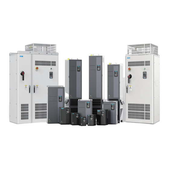
Inovance MD520 Series Quick Installation And Configuration Manual
General-purpose ac drive
Hide thumbs
Also See for MD520 Series:
- Communications manual (258 pages) ,
- Installation manual (198 pages) ,
- Hardware manual (191 pages)
Table of Contents
Advertisement
Quick Links
Advertisement
Table of Contents

Subscribe to Our Youtube Channel
Related Manuals for Inovance MD520 Series


Summary of Contents for Inovance MD520 Series
-
Page 2: Preface
Preface About This Guide The MD520 series AC drive is a general‑purpose high‑performance current vector AC drive. It is designed to control and regulate the speed and torque of three‑phase AC asynchronous motors. It can be used to drive textile machines, paper making machines, wire drawing machines, machine tools, packaging machines, food machines, fans, water pumps, and other automated production equipment. - Page 3 U60.07/F7‑11= guide. 2024 U61.10/F7‑15= Deleted 5 Parameter List. ● 000.00/F7‑16=000.00 For complete information on parameters and fault codes, see MD520 Series General‑Purpose AC Drive Parameter Guide. November Version: A10 Modified the following information: Version tag: F7‑10= 2023 Updated the fault information in section ●...
- Page 4 Damage or secondary damage caused by force majeure (natural disaster, ● earthquake, and lightning strike) The maintenance fee is charged according to the latest Price List of Inovance. If otherwise agreed upon, the terms and conditions in the agreement shall prevail. For details, see the Product Warranty Card.
-
Page 5: Table Of Contents
Table of Contents T T a a b b l l e e o o f f C C o o n n t t e e n n t t s s Preface ................1 Fundamental Safety Instructions . - Page 6 Table of Contents 4.1.4 Troubleshooting of Trial Run in Different Control Modes ......66 4.2 List of Faults and Alarms ............68 ‑5‑...
-
Page 7: Fundamental Safety Instructions
Use this equipment according to the designated environment requirements. ● Damage caused by improper use is not covered by warranty. Inovance shall take no responsibility for any personal injuries or property damage ● caused by improper use. Safety Levels and Definitions Indicates that failure to comply with the notice will result in death or severe personal injuries. - Page 8 Fundamental Safety Instructions Unpacking Do not install the equipment if you find damage, rust, or signs of use on the equipment ● or accessories upon unpacking. Do not install the equipment if you find water seepage or missing or damaged ●...
- Page 9 Fundamental Safety Instructions Handle the equipment with care during transportation and mind your steps to prevent ● personal injuries or equipment damage. When carrying the equipment with bare hands, hold the equipment casing firmly with ● care to prevent parts from falling. Failure to comply may result in personal injuries. Store and transport the equipment based on the storage and transportation ●...
- Page 10 Fundamental Safety Instructions Cover the top of the equipment with a piece of cloth or paper during installation. This is ● to prevent unwanted objects such as metal chippings, oil, and water from falling into the equipment and causing faults. After installation, remove the cloth or paper on the top of the equipment to prevent over‑temperature caused by poor ventilation due to blocked ventilation holes.
- Page 11 Fundamental Safety Instructions Before power‑on, check that the equipment is installed and wired properly and the ● motor can be restarted. Check that the power supply meets equipment requirements before power‑on to ● prevent equipment damage or a fire. After power‑on, do not open the cabinet door or protective cover of the equipment, ●...
- Page 12 Fundamental Safety Instructions Perform routine and periodic inspection and maintenance on the equipment according ● to maintenance requirements and keep a maintenance record. Repair Equipment installation, wiring, maintenance, inspection, or parts replacement must be ● performed only by professionals. Do not repair the equipment with power ON. Failure to comply will result in an electric ●...
- Page 13 Fundamental Safety Instructions Safety Label Description T12 Models T13 Models and Below Read through the safety instructions before operating the ● equipment. Failure to comply may result in death, personal injuries, or equipment damage. Do not touch the terminals or remove the cover with ●...
-
Page 14: Product Model List
Product Model List Product Model List The following table lists the mapping between product models and structures. Table –1 Mapping between product models and structures Structure Product Model Three‑Phase 380 V to 480 V Three‑Phase 200 V to 240 V Single‑Phase 200 V to 240 V MD520‑4T0.4B(S) MD520‑2T0.4B(S) - Page 15 Product Model List Structure Product Model Three‑Phase 380 V to 480 V Three‑Phase 200 V to 240 V Single‑Phase 200 V to 240 V T13 (with the MD520‑4T500‑A ‑ ‑ auxiliary power MD520‑4T500(S)‑A distribution MD520‑4T560‑A cabinet) MD520‑4T560(S)‑A MD520‑4T630‑A MD520‑4T630(S)‑A Note: (B): with the braking unit ●...
-
Page 16: Mechanical Installation
Mechanical Installation Mechanical Installation T1 to T9 Model Installation 1.1.1 Dimensions of T1 and T9 Models Figure 1‑1 Outline dimensions and mounting dimensions of T1 to T4 models Table 1–1 Outline dimensions and mounting dimensions of T1 to T4 models Mounting Mounting Hole Outline Dimension... - Page 17 Mechanical Installation Figure 1‑2 Outline dimensions and mounting dimensions of T5 to T6 models Table 1–2 Outline dimensions and mounting dimensions of T5 to T6 models Mounting Mounting Hole Outline Dimension Hole Weight mm (in.) mm (in.) Diameter Structure kg (lb) mm (in.) d x 4 T5 (without...
-
Page 18: Backplate Mounting
Mechanical Installation Figure 1‑3 Outline dimensions and mounting dimensions of T7 to T9 models Table 1–3 Outline dimensions and mounting dimensions of T7 to T9 models Mount ing Hole Mounting Hole Outline Dimension Diame Weight mm (in.) mm (in.) Structure kg (lb) mm (in.) d x 4... - Page 19 Mechanical Installation Figure 1‑4 Backplate mounting of T1 to T6 models Figure 1‑5 Backplate mounting of T7 to T9 models ‑ ‑...
-
Page 20: Through-Hole Mounting
Mechanical Installation 1.1.3 Through-Hole Mounting T1 to T6 models 1. Install the AC drive into the mounting bracket, and then fix the screws at both sides of the bracket. The following figure shows the AC drive with the bracket installed. 2. - Page 21 Mechanical Installation The following figure shows the AC drive installed in the cabinet. T7 to T9 models 1. Fix the mounting brackets to both sides of the drive. The following figure shows an AC drive with brackets mounted. ‑ ‑...
- Page 22 Mechanical Installation 2. Fix the drive with brackets to the backplate of the control cabinet. The following figure shows the drive installed by through‑hole mounting. ‑21‑...
-
Page 23: T10 To T12 Model Installation
Mechanical Installation T10 to T12 Model Installation 1.2.1 Dimensions of T10 to T12 Models (Without AC Output Reactor) Figure 1‑6 Outline dimensions and mounting dimensions of T10 to T12 models (without AC output reactor) ‑ ‑... -
Page 24: Dimensions Of T10 To T12 Models (With Ac Output Reactor)
Mechanical Installation Table 1–4 Outline dimensions and mounting dimensions of T10 to T12 models (without AC output reactor) Mounting Hole Mounting Hole Overall Dimension Diameter Weight Struc mm (in.) mm (in.) mm (in.) kg (lb) ture 1035 1086 1134 φ13 (0.5) 110 (242.5) (9.5) (5.9) -
Page 25: Installation Within The Cabinet
Mechanical Installation Table 1–5 Outline dimensions and mounting dimensions of T10 to T12 models (with AC output reactor) Mounting Mounting Hole Overall Dimension Hole Stru Weight mm (in.) mm (in.) Diameter ctur kg (lb) mm (in.) 1035 1424 1472 φ13 (0.5) 160 (352.7) (9.5) (5.9) - Page 26 Mechanical Installation Figure 1‑9 3D of the cabinet for T11 and T12 models 2. Fix the bottom mounting bracket in the nine‑fold profile cabinet. Fix the mounting bracket to the base of the nine‑fold profile cabinet by using six M5 "...
- Page 27 Mechanical Installation Figure 1‑12 Mounting the guide rails to the cabinet 4. Remove the cover from the AC drive. For details, see " 1.2.4.1 Removing the Cover " on page 28 . After the cover is removed, the auxiliary handle will be exposed. 5.
- Page 28 Mechanical Installation Figure 1‑14 Pushing the AC drive into the cabinet 6. Remove the auxiliary strap, install the four screws on the back of the AC drive to fix it to the beam in the cabinet. ‑27‑...
-
Page 29: Cover Removal And Installation
Mechanical Installation Figure 1‑15 Installing the AC drive to the beam 7. After installation is done, remove the guide rail. 8. Remove the air filter paper board at the top of the AC drive. The air filter paper board is used to prevent foreign objects such as screws from falling into the air filter during installation of the AC drive into the cabinet. -
Page 30: Installing The Cover
Mechanical Installation P P r r e e r r e e q q u u i i s s i i t t e e s s Before removing the cover, ensure that the machine has been powered off for over 10 minutes. - Page 31 Mechanical Installation 1. Hold the cover with both hands, align its upper edge with the upper edge snap‑fit joint on the chassis, and snap them together, as shown in the following figure. Then, align the six screw mounting holes on the cover with the cover mounting holes on the chassis and press them tightly against each other.
-
Page 32: T13 Model Installation
Mechanical Installation T13 Model Installation 1.3.1 Dimensions of T13 Models (Without Auxiliary Power Distribution Cabinet) ‑31‑... - Page 33 Mechanical Installation Figure 1‑17 Outline dimensions and mounting dimensions of T13 models (without auxiliary power distribution cabinet) Table 1–6 Outline dimensions and mounting dimensions of T13 models (without auxiliary power distribution cabinet) Structure Mounting Hole mm (in.) 73.5 (26.0) (2.9) (17.7) (3.3) (4.9)
-
Page 34: Dimensions Of T13 Models (With Auxiliary Power Distribution Cabinet)
Mechanical Installation 1.3.2 Dimensions of T13 Models (with Auxiliary Power Distribution Cabinet) Figure 1‑18 Outline dimensions and mounting dimensions of T13 models (with auxiliary power distribution cabinet) Table 1–7 Outline dimensions and mounting dimensions of T13 models (with auxiliary power distri‑ bution cabinet) Struc Mounting Hole... -
Page 35: Ground Levelness
Mechanical Installation Struc Overall Dimension Mounting Weight ture mm (in.) Hole kg (lb) Diameter mm (in.) 1800 2100 1205 (70.9) (82.7) (47.5) (24.0) (26.8) (0.6) (1609.4) 1.3.3 Ground levelness The installation base must be level and firm enough to bear the weight of the ●... -
Page 36: Installing Expansion Screws
Mechanical Installation 1.3.4 Installing Expansion Screws To install the cabinet on a cement floor, embed expansion nuts in advance in the floor at positions corresponding to the fixing holes of the cabinet for fixing the cabinet. The following figure shows the steps of installing expansion screws, where ❶ indicates an expansion screw, ❷... -
Page 37: Installing The External Braking Unit
Mechanical Installation During foundation design, take the following factors into consideration: sufficient ● space in front of the cabinet for inspection, and wiring and cabling of power supply cables, actuating motor cables, and system control cables. The cabinet comes with a cable trench or cable guide. Separate power cables from signal cables. - Page 38 Mechanical Installation 2. Open the cabinet door and mount the adapter busbar for the external braking unit, as shown in the following figure. 3. Connect the AC drive to the external braking unit. Note The number of required braking units is subject to actual conditions. When multiple braking units are required, connect them in parallel.
- Page 39 Mechanical Installation Figure 1‑22 Connecting the AC drive to the external braking unit Figure 1‑23 Dimensions of the position for installing the adapter busbar (unit: mm) ‑ ‑...
-
Page 40: Electrical Installation
Electrical Installation Electrical Installation Electrical Wiring Diagram Figure 2‑1 Standard electrical wiring Note For details on S1 to S4 DIP switches, see " Table 2–3 Function description of control ● circuit terminals " on page 44 For three‑phase 380–480 VAC drives, a 0.4–75 kW model differs from a 90–450 kW ●... -
Page 41: Descriptions Of Main Circuit Terminals
Electrical Installation Descriptions of Main Circuit Terminals T1 to T9 models Figure 2‑2 Layout of main circuit terminals for T1 to T4 models Figure 2‑3 Layout of main circuit terminals for T2 models (single phase) Figure 2‑4 Layout of main circuit terminals for T1 to T4 models ‑... - Page 42 Electrical Installation Figure 2‑5 Layout of main circuit terminals for T5 to T8 models Figure 2‑6 Layout of main circuit terminals for T9 models Table 2–1 Descriptions of main circuit terminals Name Function Terminal Identification R, S, T Three‑phase power supply The terminals are used to input terminals connect the three‑phase AC...
-
Page 43: Descriptions Of Control Circuit Terminals
Electrical Installation T10 to T12 models Figure 2‑7 Layout of main circuit terminals for T10 to T12 models Table 2–2 Descriptions of main circuit terminals Name Terminal Function Identification R, S, T Three‑phase power supply input The terminals are used to terminals connect the three‑phase AC power supply. - Page 44 Electrical Installation Figure 2‑8 Layout of control circuit terminals ‑43‑...
- Page 45 Electrical Installation Table 2–3 Function description of control circuit terminals Type Terminal Terminal Function Symbol Name Power +10V‑GND External +10 V The terminal is used to provide +10 V power supply supply power supply to an external unit with the maximum output current 10 mA.
- Page 46 Electrical Installation Type Function Terminal Terminal Symbol Name DO1‑CME Digital Photocoupler isolation and bipolar open collector output output Operating voltage range: 0 V to 24 V ● Output current range: 0 mA to 50mA ● Note that digital output ground CME and digital input ground COM are internally insulated, but are shorted externally by jumper as the factory settings.
- Page 47 Electrical Installation Table 2–4 STO terminal descriptions Terminal Terminal Name Performance Requirements Symbol STO1 STO channel 1 Internal connection: By default, STO1 and STO2 are connected to STO2 STO channel 2 +24V by using a jumper upon factory +24V STO1 and STO2 power delivery.
-
Page 48: Commissioning Flowchart
Commissioning Flowchart Commissioning Flowchart LED Operating Panel Dimensions The following figures show the outline and installation dimensions of the LED operating panel. Figure 3‑1 Outline and installation dimensions of LED operating panel for T1 to T4 models (mm) Figure 3‑2 Outline and installation dimensions of LED operating panel for T5 to T12 models (mm) Components The LED operating panel can be used to view the operating status and fault... - Page 49 Commissioning Flowchart Figure 3‑3 Components Table 3–1 Description of the operating panel Description Name ‑ Status Indicator ① Secondary display area It displays the following information: ② Key test and auto‑tuning ● Fault and system status monitoring ● Station number, motoring status, and ●...
- Page 50 Commissioning Flowchart Description Name Menu identification From left to right, the icons indicate the ⑧ basic menu, user‑defined parameter, modified parameter (with default values changed), and fault list. ‑ Program/Back key ⑨ ‑ Left shift key ⑩ ‑ OK key ⑪...
- Page 51 Commissioning Flowchart Name Description Navigation key In the secondary display area, press the right or left navigation key to switch the display status. Primary display area: Basic menu, user menu, and calibration menu: On ● the monitoring interface, the down key is used as the potentiometer and the left and right keys are used to switch between monitored variables.
- Page 52 Commissioning Flowchart Status indicator Table 3–3 Status indicator Status Indicator Description FWD indicator steady on The AC drive is running in the forward direction, or the reference direction is forward. REV indicator steady on The AC drive is running in the reverse direction, or the reference direction is reverse.
- Page 53 Commissioning Flowchart Description Status Indicator DRIVE indicator steady on The station No. is displayed in the auxiliary display area. DRIVE indicator off The value displayed in the auxiliary display area is not the station No. AXIS indicator steady on The axis No. is displayed in the auxiliary display area.
- Page 54 Commissioning Flowchart Description Status Indicator The primary display area displays the basic menu. Indicator steady The primary display area displays the user‑defined parameter menu. Indicator steady The primary display area displays the modified parameter (with the default Indicator steady value changed) menu. The primary display area displays the fault menu.
- Page 55 Commissioning Flowchart Actual Actual Actual Actual Display Display Display Display Data Data Data Data ‑ ‑ ‑ ‑ ‑ ‑ ‑...
-
Page 56: Basic Commissioning Flowchart
Commissioning Flowchart Basic Commissioning Flowchart Figure 3‑4 Basic commissioning flowchart Table 3–5 Basic commissioning flowchart Step Related Parameter Check before power‑on Power‑on Parameter initialization FP‑01 View the software version. F7‑10, F7‑11, F7‑15, F7‑16 ‑55‑... - Page 57 Commissioning Flowchart Step Related Parameter Set motor parameters. F1‑00 to F1‑05 Note that you must set the motor type. Set encoder parameters. F1‑27, F1‑28, F1‑34 Set the control mode. F0‑01 Perform motor parameter auto‑tuning. F1‑37 Set the command source. F0‑02 Select the frequency source.
-
Page 58: Commissioning Flowchart In V/F Control Mode
Commissioning Flowchart Commissioning Flowchart in V/f Control Mode Figure 3‑5 Commissioning flowchart in V/f control mode ‑57‑... -
Page 59: Commissioning Flowchart In Svc/Fvc Control Mode
Commissioning Flowchart Commissioning Flowchart in SVC/FVC Control Mode Figure 3‑6 Commissioning flowchart in SVC/FVC control mode ‑ ‑... -
Page 60: Commissioning Flowchart In Pmvvc Control Mode
Commissioning Flowchart Commissioning Flowchart in PMVVC Control Mode Figure 3‑7 Commissioning flowchart in PMVVC control mode ‑59‑... -
Page 61: Troubleshooting
Figure 4‑1 Display of faults Do not repair or modify the AC drive by yourself. In case of any fault that cannot be rectified, contact the agent or Inovance for technical support. 4.1.2 Start After Fault Occurrence View the current fault code, fault subcode, fault information, minor fault code, minor fault subcode, minor fault information, warning code, warning subcode, warning information through the operating panel. - Page 62 Troubleshooting Table 4–1 Fault view and start method after fault occurrence Stage Solution Description In faulty status Fault record 1: View the current fault code, View the record through H0‑00 to H0‑53. fault subcode, fault information, minor fault code, minor fault subcode, minor fault information, warning code, warning subcode, warning information through the operating panel.
- Page 63 Troubleshooting Stage Solution Description Reset mode to 1. Set any of F4‑00 to F4‑09 to 9 (fault reset). clear faults 2. Verify that F7‑02 is set to 1 (default value), Press the STOP/RES key on the operating panel. indicating that the STOP/RES key is available in any operating mode.
-
Page 64: Common Troubleshooting
Re‑connect the 8‑pin and 40‑pin disconnected from the flat cables. driver board and operating panel. The pre‑charge resistor Contact the agent or Inovance for of the AC drive is technical support. damaged. The control board or the operating panel is faulty. - Page 65 Replace the fan or clean the air frequently. damaged, or the air duct duct. is blocked. Devices (thermistor or Contact the agent or Inovance for other devices) inside the technical support. AC drive are damaged. The motor does The wiring between the...
- Page 66 The jumper between OP Secure the jumper between OP and +24 V becomes and +24V. loose. The control board is Contact the agent or Inovance for faulty. technical support. The motor speed The encoder is faulty. Replace the encoder disk and...
- Page 67 Troubleshooting 4.1.4 Troubleshooting of Trial Run in Different Control Modes SVC mode (F0‑01= 0 (default)) ● In this mode, the drive controls the motor speed and torque without an encoder for speed feedback. Auto‑tuning on motor parameters is required to obtain the motor parameters.
- Page 68 Troubleshooting Table 4–4 Troubleshooting in FVC mode Problem Solution Overload or overcurrent Set the encoder resolution (PPR), encoder type and encoder fault detected during direction correctly. startup Overload or overcurrent is Set motor parameters F1‑01 to F1‑05 according to the motor detected during motor nameplate.
- Page 69 (F3‑18, default: 150%) properly by the step value of 10%. The permissible minimum value is 50%. List of Faults and Alarms For complete information on fault and alarm codes, see MD520 Series General‑ Purpose AC Drive Parameter Guide. ‑ ‑...
- Page 70 *19011712A02*...
Need help?
Do you have a question about the MD520 Series and is the answer not in the manual?
Questions and answers