Table of Contents
Advertisement
Advertisement
Table of Contents

Related Manuals for Inovance 810 Series


Summary of Contents for Inovance 810 Series
- Page 1 User Guide 810 Series Power Supply Unit User Guide Data code 19010680...
-
Page 2: Preface
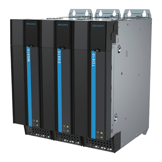
The 810 series power supply unit covers a power range of 22 kW, 45 kW, 110 kW, 160 kW, and 355 kW and has a total of five outline structures. It is divided into the booksize unit and the vertical tower unit. - Page 3 Preface Combined Schematic Diagram of Combination Application Scheme Effects This scheme is able to implement stable running and accurate positioning control along with the small and medium inertia ISMH series high response servo motor, and is applicable for such MD810 series automation equipment power supply as gravure presses, flexo...
- Page 4 Inovance to ensure correct use. For More Documents The 810 series power supply unit applies to the MD810, IS810, ES810, and TD810 series drive units. This manual describes only data such as the product information, installation, communication, troubleshooting and function parameters of the power supply unit.
- Page 5 Preface Certification Directives Standard EMC directives 2014/30/EU EN 61800-3 LVD directives 2014/35/EU EN 61800-5-1 RoHS directives 2011/65/EU EN 50581 EN 61800-5-1 ◆ The above EMC directives are complied with only when the EMC electric installation requirements are strictly observed. ◆ Certification marks on the product nameplate indicate compliance with the corresponding certificates and standards.
-
Page 6: Revision History
Revision History Revision History Date Version Description Change March 2018 First release Added information about TD810 series. March 2019 Added information about the PROFINET-to-CANopen network bridge. - 5 -... -
Page 7: Table Of Contents
Contents Contents Preface ............................1 Revision History ......................... 5 Safety Instructions ........................11 Safety Precautions ......................11 Safety Levels and Definitions ................... 11 Safety Instructions ......................12 Safety Signs ........................16 1 Product Information ......................17 1.1 Nameplate and Model Number .................. 18 1.2 Components ........................ - Page 8 Contents ..........54 3.1.1 Assignment of Terminals in the Power Supply Unit ..........56 3.1.2 Description of Terminals in the Power Supply Unit ....................58 3.1.3 Cable Selection ....................59 3.1.4 System Grounding 3.2 Control Circuit Wiring ....................60 ..........60 3.2.1 Assignment of Terminals in the Power Supply Unit ..............
- Page 9 Contents ........101 6.1.2 Description of Parameter Communication Addresses ......... 103 6.1.3 Modbus-Specific Parameter Communication Addresses 6.2 Modbus Communication ..................105 ......................105 6.2.1 Networking ..................105 6.2.2 Interface Description ................105 6.2.3 Communication Performance ................... 106 6.2.4 Related Parameters ..............
- Page 10 Contents ..................159 6.6.4 Configuration on STEP 7 ................164 6.6.5 Configuration on TIA Portal ..................... 167 6.6.6 Auxiliary Functions ................167 6.6.7 Error Reporting and Diagnosis ......................168 6.6.8 Monitoring ... 168 6.6.9 Configuration of PROFINET Network Bridge Used with Siemens PLC S1500 7 Troubleshooting ........................
- Page 11 Contents ..................218 9.5.1 MCCB and Contactor ........................219 9.5.2 Lugs ....................223 9.5.3 AC Input Reactor ..................... 226 9.5.4 External EMC Filter Appendix A Standards Compliance ..................234 A.1 CE Certification ......................234 ............... 234 A.1.1 CE Low Voltage Directive Compliance ................
-
Page 12: Safety Instructions
4) Use this equipment according to the designated environment requirements. Damage caused by improper usage is not covered by warranty. 5) Inovance shall take no responsibility for any personal injuries or property damage caused by improper usage. Safety Levels and Definitions... -
Page 13: Safety Instructions
Safety Instructions Safety Instructions Unpacking CAUTION ◆ Check whether the packing is intact and whether there is damage, water seepage, damp, and deformation. ◆ Unpack the package by following the package sequence. Do not hit the package with force. ◆ Check whether there are damage, rust, or injuries on the surface of the equipment or equipment accessories. - Page 14 Safety Instructions Installation WARNING ◆ Thoroughly read the safety instructions and user guide before installation. ◆ Do not modify this equipment. ◆ Do not rotate the equipment components or loosen fixed bolts (especially those marked in red) on equipment components. ◆...
- Page 15 Safety Instructions WARNING ◆ Never connect the power cable to output terminals of the equipment. Failure to comply may cause equipment damage or even a fire. ◆ When connecting a drive with the motor, make sure that the phase sequences of the drive and motor terminals are consistent to prevent reverse motor rotation.
- Page 16 Safety Instructions Maintenance DANGER ◆ Equipment installation, wiring, maintenance, inspection, or parts replacement must be performed by only professionals. ◆ Do not maintain the equipment at power-on. Failure to comply will result in an electric shock. ◆ Before maintenance, cut off all equipment power supplies and wait at least 10 minutes. WARNING ◆...
-
Page 17: Safety Signs
Safety Instructions Safety Signs ■ Description of safety signs in the user guide Read the user guide before installation and operation. Reliably ground the system and equipment. Danger! High temperature! Prevent personal injuries caused by machines. High voltage! Wait xx minutes before further operations. **min ■... -
Page 18: Product Information
1 Product Information 1 Product Information The 810 series power supply unit applies to the MD810, IS810, ES810, and TD810 series drive units. This chapter describes only the product information about the power supply unit. For product information about the drive units, refer to their manuals. -
Page 19: Nameplate And Model Number
INPUT: 3PH AC 380-480V 112.0A 50/60Hz Rated input OUTPUT: DC 537V-679V 110.0A 45kW Rated output S/N: XXXXXXXXXXXXXXXX Serial No. Suzhou Inovance Technology Co. ,Ltd. Nameplate of ES810 series power supply unit Product Certi ficates MODEL: ES810-20M4T240-00 model Rated input INPUT: 3PH AC 380-480V 196.0A 50/60Hz... - Page 20 1 Product Information ES810 - 20M 4T 110 - 1 0 Mark Series Mark Power Supply ES810 Electro-hydrauli c serv o Default Mark Unit Type Power supply uni t Optional Functional Mark Components Mark Voltage Class No optional built-in braking unit 380 V to 480 V Built-in braking uni t (Optional for only...
-
Page 21: Components
1 Product Information 1.2 Components The 810 series power supply unit is divided into the MD810, ES810, and TD810 series power supply unit. The following figure shows the description of components: Mounting hole 24 V power input STO protective power input... -
Page 22: Mechanical Installation
2 Mechanical Installation 2 Mechanical Installation The 810 series power supply unit applies to the MD810, IS810, ES810, and TD810 series drive units. This chapter describes only the mechanical installation of the power supply unit. For the mechanical installation of the drive units, refer to their manuals. -
Page 23: Storage Precautions
The operating ambient temperature of the power supply unit must not exceed an allowable temperature range (-10°C to 50°C). 2) Altitude: When the installation altitude exceeds 1000 m, the 810 series power supply unit must be derated according to any recommended capacitance value. - Page 24 2 Mechanical Installation Strong vibration Dust, oil Sunlight Vibration less than 0.6 g High Combustible temperature material and humidity Corrosive, explosive Install on the surface of an Ambient -10°C to 50°C and combustible gas incombustible object Figure 2-1 Installation environment 7) The drive units must be installed in a fireproof cabinet with doors that provide effective electrical and mechanical protection.
-
Page 25: System Selection
2 Mechanical Installation 2.2 System Selection 2.2.1 System Selection Flowchart Start Determine load distribution and motor requirements. Determine the motor type, quantity and specifications. Drive unit selection Power calculation Power supply unit selection Bus current calculation Determine a combination and arrangement mode. Selection of Is a common... -
Page 26: Selection Of The Load And Motor
2 Mechanical Installation 2.2.2 Selection of the Load and Motor 1) Determine a motor type and quantity according to the load and operating mode of the mechanical equipment. 2) Determine the requirements of the mechanical equipment for the power, torque, speed, startup, speed regulation, braking, overload, heating, and temperature rise of the motor. - Page 27 2 Mechanical Installation Table 2-1 Parameter specifications of the power supply unit Rated Power AC Input Current Power Supply Unit Output Power Capacity Current Braking Unit Carrying Model Current (kW) (kVA) Capacity (A) Input voltage 380 VAC to 480 VAC (Operating range: 323 VAC to 528 VAC) Output voltage 537 VDC to 679 VDC MD810-20M4T22GXXX Optional built-in...
-
Page 28: System Combination And Arrangement
Single or dual rack installation is allowed. A power supply unit may be located between or on the left side of the drive units. The 810 series power supply unit applies to the MD810, IS810, ES810, and TD810 series drive units. For specific installation of the power supply unit and the drive units, refer to their manuals. - Page 29 2 Mechanical Installation ■ Dual rack installation If space in the cabinet is limited, dual rack installation can be performed. A power supply unit is generally placed on the left during dual rack installation. If there are two power supply units, it is recommended to provide one power supply unit in each rack. If there are more power supply units, it is recommended to separately install them in multiple cabinets.
-
Page 30: System Selection Precautions
2.3 Cabinet Design 2.3.1 Space Requirements The 810 series power supply unit is divided into the booksize unit (50 mm, 100 mm, 200 mm and 300 mm wide) and the vertical tower unit (180 mm wide). The recommended installation methods are single rack installation and dual rack installation. The following figure table and figures show the minimum clearance between two racks during dual rack installation. - Page 31 2 Mechanical Installation Air guide plate 2200 ≥500 Figure 2-3 Heat dissipation clearances for dual rack installation of the booksize unit 2200 ≥500 Figure 2-4 Heat dissipation clearances for the vertical tower unit ◆ The vertical tower units are designed to be installed vertically to enable correct heat dissipation.
-
Page 32: Mounting Backplate Design Requirements
2 Mechanical Installation 2.3.2 Mounting Backplate Design Requirements 1 Thickness and stiffness reinforcing principles of the mounting backplate To avoid damage to the power supply unit during transportation and ensure its normal operation, the mounting backplate of the power supply unit must have enough stiffness and strength and a thickness of not less than 2 mm. - Page 33 2 Mechanical Installation ◆ The relative position of the mounting holes of the power supply unit must be accurate to ensure that the built-in DC busbar of the power supply unit is reliably connected. It is strongly recommended to process mounting holes during backplate processing.
-
Page 34: Cabinet Cooling Design
After a power supply unit enters the cabinet, the following table shows the minimum effective area of the air inlet. Table 2-3 Minimum effective area of the cabinet air inlet of the 810 series power supply unit Module Power Minimum Effective Ventilation Area of the Cabinet Air Inlet (cm... - Page 35 2 Exhaust air design at the top Hot air in the cabinet must be able to be smoothly discharged to outside the cabinet to ensure full cooling of the 810 series power supply unit. Passive or active air discharge ■ Passive air discharge (Direct air discharge) Passive air discharge is to guide exhaust air from the power supply unit to be discharged to outside the cabinet from the air outlet at the top of the cabinet.
- Page 36 2 Mechanical Installation Therefore, an isolating device must be used in the passive air discharge cabinet to prevent backflow of hot air. An isolating device may be a plate or exhaust duct. Air guide plate Air guide plate that Air guide plate that that prevents prevents backflow prevents backflow...
- Page 37 The total air flow must not be smaller than the sum of air flows of all power supply units in the cabinet to ensure that hot air in the cabinet can be smoothly discharged to outside the cabinet. The cooling air flow required for the 810 series power supply unit is as follows: Table 2-5 Cooling air flow of the power supply unit...
- Page 38 2 Mechanical Installation This column in the fan specifications is the maximum air flow Qmax of this fan Fan maximum air flow Qmax Figure 2-8 Q of a system fan ≥200 mm Cold air Hot air Cabinet air inlet Figure 2-9 Cabinet exhaust air system of the power supply unit - 37 -...
-
Page 39: Combined Installation
2 Mechanical Installation ◆ Pay attention to the air draft direction during fan installation to ensure air draft from inside to outside of the cabinet and avoid overheat or damage to the power supply unit due to discharge failure of hot air. ◆... - Page 40 2 Mechanical Installation ■ Dual rack installation Booksize unit Vertical tower unit Air guide plate Air guide plate Air guide plate Air guide plate ◆ An insulation deflector may be selectively installed in the upper rack of units during dual rack installation. ◆...
-
Page 41: Installation Of The Power Supply Unit
2 Mechanical Installation 2.4.2 Installation of the Power Supply Unit This section describes only the installation of the power supply unit. For details of the installation of the drive units, refer to their manuals. 1 Cover removal and installation Cover Removal 1) Lift the translucent 2) Remove the upper cover by 3) Pull the whole... - Page 42 2 Mechanical Installation Cover Installation 1) Align the power terminal 2) Insert the operating panel. 3) Align the upper cover cover with the position of with the position of the the clasp of the bus seat. clasp. Press the upper Press the power terminal cover to clasp and fix it.
- Page 43 2 Mechanical Installation 2 Backplate mounting ■ Backplate mounting of 22 kW power supply unit Figure 2-10 Backplate mounting of 22 kW power supply unit (50 mm wide) ■ Backplate mounting of 45 kW power supply unit Figure 2-11 Backplate mounting of 45 kW power supply unit (100 mm wide) - 42 -...
- Page 44 2 Mechanical Installation ■ Backplate mounting of 110 kW power supply unit Figure 2-12 Backplate mounting of 110kW power supply unit (200mm wide) ■ Backplate mounting of 160 kW power supply unit Figure 2-13 Backplate mounting of 160 kW power supply unit (300mm wide) - 43 -...
- Page 45 2 Mechanical Installation The installation procedure is as follows: 1) Insert a screwdriver in the left and right clasps of the power terminal cover and push them up lightly to loosen the clasps. 2) Turn downwards the terminal cover loosen from the clasps and remove it from the shell.
- Page 46 2 Mechanical Installation 3 Through-hole mounting ■ Through-hole mounting brackets Upper and lower through-hole mounting brackets of 50 mm wide unit Upper and lower through-hole mounting brackets of 100mm wide unit Upper and lower through-hole mounting brackets of 200mm wide unit Upper and lower through-hole mounting brackets of 300mm wide unit ■...
- Page 47 2 Mechanical Installation 4 Installation of common bus external power terminal The common bus external power terminal used for the 810 series power supply unit is not installed in the factory. If necessary, assemble it by yourself. ■ Installation example of 100 A common bus external power terminal (22 kW power...
- Page 48 2 Mechanical Installation ■ Installation example of 200 A common bus external power terminal (45 kW power supply unit) Reserved holes used to install a common bus external power terminal Common bus external power terminal (200 A) M4×30 M5×20 Tighten corresponding screws at the following torque: M4: 1.0 to 1.4 N.m, M5: 2.5 to 3 N.m Insert the operating panel.
- Page 49 2 Mechanical Installation ■ Installation example of 200 A common bus external power terminal (110 kW and 160 kW power supply units) The installation procedure of the 110 kW and 160 kW power supply units is the same as the 45 kW power supply unit. The following figures show the position examples after the installation is completed: Installation position example of 110 kW power supply Installation position example of 160 kW power supply...
-
Page 50: Cabinet Installation
2 Mechanical Installation 2.4.3 Cabinet Installation Step 1: Pre-install screws on the mounting backplate. Keep an about 10 mm clearance between the screws and the backplate to ensure that the module can be hung. Step 2: Remove the cover of the unit. "2.4.2 Installation of the Power Supply Unit". - Page 51 2 Mechanical Installation Step 4: Install the EMC grounding aluminum bar. To achieve correct grounding in the overall system and form an entirety (equipotential body), when the power supply unit and multiple drive units are installed on the installation face, grounding aluminum bars must be added on the mounting holes between units and fixed on the installation face to ensure that units are connected together using the grounding aluminum bars.
- Page 52 2 Mechanical Installation ◆ Before connecting the built-in busbar, remove the left and right bus protective baffles in the top cover with tools such as nipper pliers/ diagonal pliers. The following figure shows the position of the bus protective baffle. NOTE protective baffle...
-
Page 53: Auxiliary Installation For Cabinet Transportation
2 Mechanical Installation Step 10: Install the wind scooper option. Step 11: Finish the installation. 2.5 Auxiliary Installation for Cabinet Transportation The following principles must be followed before cabinet transportation to avoid damage to the power supply unit during cabinet transportation: ■... -
Page 54: Electrical Installation
3 Electrical Installation 3 Electrical Installation The 810 series power supply unit applies to the MD810, IS810, ES810, and TD810 series drive units. This chapter describes only the electrical installation of the power supply unit. For the electrical installation of the drive units, refer to their manuals. -
Page 55: Main Circuit Wiring
3 Electrical Installation 3.1 Main Circuit Wiring 3.1.1 Assignment of Terminals in the Power Supply Unit Figure 3-1 Assignment and dimensions of terminals in power supply unit (booksize, unit: - 54 -... - Page 56 Open the cover Side Figure 3-2 Assignment and dimensions of terminals in power supply unit (vertical tower, unit: Table 3-1 Power cable selection of 810 series power supply unit Recommended Input IEC AC INPUT Cable Specifications Power Supply Unit Model...
-
Page 57: Description Of Terminals In The Power Supply Unit
"Table 3-1 Power cable selection of 810 series power supply unit" ■ The filter must be installed near the input terminals of the power supply unit and the connecting cable must be smaller than 30 cm. The grounding terminals of the filter and power supply unit must be connected together. - Page 58 ■ Do not connect the grounding terminal to the N terminal of the power supply. ■ The size of protective grounding conductors must be selected according to "Table 3-1 Power cable selection of 810 series power supply unit". ■ Use proper grounding cable with yellow/green insulation for protective grounding conductor.
-
Page 59: Cable Selection
3 Electrical Installation Non-spraying metal installation surface Filter Electric reactor Figure 3-3 Protective grounding connection of main circuit terminals 6) VDR and safety capacitor (EMC) jumpers to ground Where a leakage circuit breaker is configured, if leakage protector is tripped during startup, the screw of the safety capacitor (EMC) jumper to ground may be removed. -
Page 60: System Grounding
3 Electrical Installation ■ Recommended power cable type — symmetrical shielded cable: PE c onductor core and shield Shield Shield Figure 3-5 Recommended power cable type ■ Non-recommended power cable type: Shield Figure 3-6 Non-recommended power cable type 2) Recommended lug selection Reference data for recommended lugs (Suzhou Yuanli Metal Enterprise Co., Ltd) GTNR series TNR series... -
Page 61: Control Circuit Wiring
3 Electrical Installation Line Power supply unit Drive unit Input electric reactor Filter Load System grounding copper bar Figure 3-7 System protective grounding connection 3.2 Control Circuit Wiring 3.2.1 Assignment of Terminals in the Power Supply Unit Control terminals PROFINET communication terminals DIP switch ProfinetA... - Page 62 3 Electrical Installation Table 3-2 Definitions of control circuit terminals Interface Port Type Function Performance Indicator Name Data sending+ The yellow indicator indicates PROFINET Data sending- that the link communication connection is interfaces normal. The green (ProfinetA/ indicator indicates Data receiving+ ProfinetB) that the signal is normal.
- Page 63 3 Electrical Installation Interface Port Type Function Performance Indicator Name Positive of external C485+ RS485 communication Modbus communication protocol signal Negative of external supported C485- RS485 communication Synchronous CAN and RS485 signal communication CAN_H of CAN CAN2H (CN2) communication signal Dedicated CAN for synchronous control CAN_L of CAN CAN2L...
- Page 64 3 Electrical Installation Interface Port Type Function Performance Indicator Name Unconnected Unconnected Profibus-DP bus plus Unconnected Profibus-DP Ground of Profibus-DP CGND2 CGND2 communication bus power supply Profibus-DP bus power terminals (CN5) supply Unconnected Profibus-DP bus minus Unconnected - 63 -...
- Page 65 3 Electrical Installation Table 3-3 Definition of DIP switches of the power supply unit Terminal ID Terminal Name Function Description Toggle Position Connect the termination resistor when switches 1 and 2 are turned on. Selection of RS485 termination resistor Connect no termination resistor when switches 1 and 2 are turned off.
-
Page 66: Control Circuit Wiring Requirements
90 degrees. Recommended cabling diagram: Power cable Power cable 90° Min. 200 mm Min. 300 mm Motor cable Control cable 810 series power supply unit Control cable Regenerative Min. 500 mm 90° resistor cable Motor cable Control cable Min. -
Page 67: Description Of Control Circuit Wiring
3 Electrical Installation 3.2.3 Description of Control Circuit Wiring 1) DI terminals DI terminals are compatible with sink (NPN) and source (PNP) wiring methods. ■ Sink wiring method +24V +24V +VCC Signal Signal External co ntrol ler Power supply unit control board External co ntrol ler Power supply unit control board Sink conne ction method using the int ernal 24 V... - Page 68 3 Electrical Installation If the internal 24 V power supply of the power supply unit is used, the jumper between the +24 V and the OP must be removed, the OP and COM must be connected together, and the +24 V and the common terminal of the external controller must be connected together.
- Page 69 3 Electrical Installation Warning ◆ If relay output terminals are connected to 220 V dangerous voltage, pay attention to distinguishing them from the surrounding safety extra-low voltage circuit terminals to ensure no misconnection. It must be taken into consideration that wiring must meet the requirements for reinforced insulation.
-
Page 70: Panel Operations
4 Panel Operations 4 Panel Operations The 810 series power supply unit applies to the MD810, IS810, ES810, and TD810 series drive units. This chapter describes only the panel operations of the power supply unit. For the panel operations of the drive units, refer to their manuals. -
Page 71: Led Display Area
4 Panel Operations Indicator State State Description Off: Speed mode ERR/TC TUNE ON (green): Torque control mode ERR/TC/TUNE ERR/TC TUNE Fault/Torque control/ Auto-tuning indicator Slow flash (green): Auto-tuning state (1 time/s) ERR/TC TUNE Quick flash (red): fault state (4 times/s) ERR/TC TUNE Speed/Frequency unit: RPM/Hz RPM/... -
Page 72: Parameter Viewing And Modification Methods
◆ Confirm displayed parameter setting. ENTER 4.1.4 Parameter Viewing and Modification Methods The LED operating panel of the 810 series power supply uses a three-level menu structure to perform operations such as parameter settings. After entering a menu at every level, press to perform modification when a display bit flashes. -
Page 73: Parameter Viewing
AC drive is in the STOP status. 4.1.5 Parameter Viewing The 810 series power supply units have many parameters and three parameter viewing methods are provided. The default is the basic viewing method (to view all parameter groups). - Page 74 4 Panel Operations Customized mode User-modified mode Basic mode (Parameters are customized Status parameter Long press for 1s (Only modified (Full parameters) (Default interface) for only group FE.) parameters are listed.) MODE SHIFT SHIFT SHIFT TUNE FP-03 = x1 FP-03 = 1x If no key operation is performed within 2s, the system backs to...
- Page 75 4 Panel Operations Parameter Parameter Function Default Setting Range Description Ones: Selection of Determine Selection whether to group display of function display user- 0: Disabled; 1: Enabled FP-03 parameter defined groups Tens: Selection of group and user-modified display parameter group display groups.
- Page 76 4 Panel Operations ■ Viewing user-modified parameters Long press on the panel to enter the "user-modified parameter" mode MODE and view parameters different from defaults. This mode facilitates your access to modified parameters. User-modified parameters are listed in user-modified parameter groups, i.e. the current setting values are different from defaults.
- Page 77 4 Panel Operations High F7-03 Binary Hexadecimal The method of viewing other state parameters is the same as F7-03 (Running display parameter 1). The corresponding relation between the state parameters and every byte of F7-03 (Running display parameter 1), F7-04 (Running display parameter 2), and F7-05 (Stop display parameter) is as follows: Parameter Function...
- Page 78 4 Panel Operations Parameter Function Default Setting Range Parameter Description If the following parameters need to be displayed in running, set their corresponding positions to 1. After converting this binary number to a hexadecimal number, set it in F7-04. Meanings of Running low 8 bits display...
-
Page 79: External Lcd Operating Panel
4 Panel Operations 4.2 External LCD Operating Panel The external LCD operating panel (model SOP-20) is Inovance's new-generation commissioning aid of frequency control system and supports products such as MD810, IS810, ES810, and TD810 series. The external LCD operating panel has a wide power supply range and LCD display, supports multibus and applies to the single-drive/ multidrive system. -
Page 80: Wiring
LCD operating panel to the RJ45B interface at the top of the 810 series power supply unit using a standard network cable. The following figure shows the interface of the 810 series power supply unit. - 79 -... -
Page 81: Status Viewing
4 Panel Operations RJ45A RJ45B 4.2.3 Status Viewing After the external LCD operating panel wiring is started, the main interface is the status information interface of the power supply unit with the current default station No., as shown in the following figure. Press to view more status information. -
Page 82: Parameter Setting
4 Panel Operations 1: MD810 power supply uni t Runnable 1:MD810 power supply unit Runnable 1 6: 5 2: 1 5 Back Select Figure 4-8 Equipment list page 4.2.4 Parameter Setting Press on the main page to enter the parameter setting interface. The following figure shows the setting procedure. -
Page 83: Parameter Copy
4 Panel Operations 4.2.5 Parameter Copy Figure 4-10 Parameter uploading 1: MD810 power supply unit 1: MD810 power supply unit Runnable Runnable 1: MD810 power supply unit Runnable 01 Parameter copy 01 Read parameters 03 Device operation 02 Device burning 02 Write parameters 04 Authority management 03 Keypad upgrading 05 System setting... -
Page 84: Fault Query
4.3 InoDriveShop InoDriveShop is a piece of commissioning software developed for the 810 series power supply unit. The following figure shows the software icon. The functions such as real-time monitoring, parameter configuration, oscilloscope, Profibus-DP bus configuration, and emergency stop are implemented on the PC using the InoDriveShop commissioning software. -
Page 85: Parameter Description
5 Parameter Description 5 Parameter Description The 810 series power supply unit applies to the MD810, IS810, ES810, and TD810 series drive units. This chapter describes only the parameter description of the power supply unit. For the parameter description of the drive units, refer to their manuals. - Page 86 5 Parameter Description Parameter Function Default Setting Range Parameter Description When the bus voltage Start voltage is higher than the F1-02 of braking unit 760 V 700 V to 800 V setting value, the actuation braking unit is actuated. When the bus voltage is higher than the F1-02 setting value, the braking unit is actuated, playing a role in reducing the bus voltage.
- Page 87 5 Parameter Description imbalance is not protected. When the hundred's digit is set to 1, three-phase imbalance is protected. When F1-11 is set to 0, the power supply unit does not detect any fault. When the system continues to run, the risk of damage to the system will increase. Parameter Function Default...
-
Page 88: Information Exchange Setting Between The Power Supply And Drive Units
5 Parameter Description 5.3 Information Exchange Setting Between the Power Supply and Drive Units When the power supply unit is faulty, it transfers a message to the drive unit that then performs corresponding actions according to message contents. Parameter Function Default Setting Range Parameter Description... - Page 89 5 Parameter Description Parameter Function Default Setting Range Parameter Description 1: Run When any EEPROM fault Drive unit occurs in the power supply 2: Coast to stop protection action F2-11 unit, it transfers the "stop by against EEPROM 3: Stop by a a setting method"...
-
Page 90: Input Terminal Functions
5 Parameter Description 5.4 Input Terminal Functions The 810 series power supply unit is provided with 5 multi-functional DI terminals as standard configuration. You can set different functions for input terminals according to the actual application respectively. Parameter Function Default... - Page 91 5 Parameter Description If a maloperation is caused due to interference to an input terminal, the parameters shown in the following table can be increased to enhance anti-interference performance, However, the increase of DI filter time will reduce the response of DI terminals.
-
Page 92: Relay Output Terminal Functions
5 Parameter Description 5.5 Relay Output Terminal Functions The 810 series power supply unit is provided with 3 groups of multi-functional relay output terminals. Setting Parameter Function Default Parameter Description Range T1A, T1B and T1C F5-00 output function selection T2A, T2B and T2C... -
Page 93: Fault Record Group
5 Parameter Description Setting Function Description Value Overvoltage output When the power supply unit detects that the bus is in overvoltage of bus voltage state, ON signals are output. Normal output of When the power supply unit detects that the bus voltage is bus voltage normal, ON signals are output. - Page 94 5 Parameter Description Stop command sent from the Stop command sent from the power supply unit FA-12 power supply unit upon the upon the fifth fault last fault Total power-on time upon the FA-13 Total power-on time upon the fifth fault (h) last fault (h) Total power-on time upon the FA-14 Total power-on time upon the fifth fault (min)
- Page 95 5 Parameter Description FA-41 Fault subcode upon the third fault FA-42 Bus voltage upon the third fault FA-43 Module temperature upon the third fault FA-44 Braking piping temperature upon the third fault FA-45 Braking circuit current upon the third fault FA-46 Power grid voltage Usr upon the third fault FA-47 Power grid voltage Ust upon the third fault FA-48 Power grid voltage Utr upon the third fault...
-
Page 96: Parameter Management
5 Parameter Description FA-87 Power grid voltage Ust upon the first fault FA-88 Power grid voltage Utr upon the first fault FA-89 Degree of three-phase imbalance upon the first fault FA-90 DI status upon the first fault FA-91 RO status upon the first fault The same as FA-00 to FA-15 Stop command sent from the power supply unit FA-92... - Page 97 5 Parameter Description Parameter Function Default Setting Range Parameter Description After it is set to 1, any Parameter 0: Disabled modification to all FP-02 modification 1: Enabled function parameters is selection disabled. Set FP-02 to 1 to prevent any modification after you set function parameters. Parameter Function Default...
-
Page 98: Monitoring Parameters
5 Parameter Description 5.8 Monitoring Parameters Parameters in group U0 are used to monitor running status information of the power supply unit. You can view them via the panel to facilitate site commissioning or read parameter group values via communication to perform host controller monitoring. The communication address is 0x7000~0x7021. - Page 99 5 Parameter Description Minimum Monitoring Parameter Function Parameter Description Unit Range Display the current DI status value. After it is converted into binary data, every bit corresponds to one DI signal. The value 1 indicates that the input is high level. The value 0 indicates that the input is low level.
- Page 100 5 Parameter Description Minimum Monitoring Parameter Function Parameter Description Unit Range Display the fault subcode Current fault U0-13 1 to 65535 corresponding to the current fault subcode code of the power supply unit. Display the current DI status value. After it is converted into binary data, every bit corresponds to one DI signal.
- Page 101 5 Parameter Description Minimum Monitoring Parameter Function Parameter Description Unit Range Power-on time Display the running milliseconds of U0-23 for this time 0 to 999 the power supply unit from power-on (ms) to now for this time. Command 0: The fan stops running U0-24 word for fan 0 to 1...
-
Page 102: Communication
6 Communication 6 Communication The 810 series power supply unit applies to the MD810, IS810, ES810, and TD810 series drive units. This chapter describes only the communication of the power supply unit. For the communication of the drive units, refer to their manuals. - Page 103 6 Communication In addition, writing basic function parameters and performing power-off save cause frequent operations on EEPROM, reducing the service life of EEPROM. Therefore, some basic function parameters are modified by changing the values in RAM through communication without being stored. See the following table.
-
Page 104: Modbus-Specific Parameter Communication Addresses
6 Communication 6.1.3 Modbus-Specific Parameter Communication Addresses Parameter Parameter Description Address Communication Monitoring Parameters *Communication setting value (decimal) -10000 to 10000 Communication setting values are percentage of relative values. 10000 1000H and -10000 correspond to 100.00% and -100.00%, respectively. For frequency dimension data, this percentage is a percentage of relative maximum frequency (F0-10). - Page 105 6 Communication Parameter Parameter Description Address Description of power supply unit faults 0000: No fault 0001: Hardware fault 0002: Overcurrent during acceleration 0003: Overcurrent during deceleration 0004: Overcurrent at constant speed 0005: Overvoltage during acceleration 0006: Overvoltage during deceleration 0007: Overvoltage at constant speed 0009: Undervoltage fault 000A: Drive overload 000B: Motor overload...
-
Page 106: Modbus Communication
6 Communication 6.2 Modbus Communication 6.2.1 Networking Commissioning Basic networ k test Par ty Modbus Figure 6-1 Modbus communication networking 6.2.2 Interface Description The terminal names of 3-pin connection terminals are C485+, C485-, and CGND from left to right, as shown in the following figure: CGND C485- C485+... -
Page 107: Related Parameters
6 Communication 6.2.4 Related Parameters Parameter Name Default Setting Range Parameter Description This parameter is used to set a data transmission rate between the host controller and the power supply unit. 0: 300 bps 5: 9600 bps The larger the baud rate is, 1: 600 bps 6: 19200 bps the faster the communication... -
Page 108: Modbus Communication Protocol
(Err16). 6.2.5 Modbus Communication Protocol The 810 series power supply unit provides RS485 communication interfaces and supports the Modbus-RTU slave communication protocol. You can implement centralized control with a computer or PLC. You can set the power supply unit RUN command, modify or read parameters, and read the operating state and fault information of the power supply unit using this communication protocol. -
Page 109: Communication Data Frame Structure
3.5 bytes 3.5 bytes The built-in communication protocol of the 810 series power supply unit is the Modbus- RTU slave communication protocol. It enables the power supply unit to respond to an "inquiry/command" of the host or perform corresponding action and communication data response according to an "inquiry/command"... - Page 110 6 Communication > 3.5 bytes 1 byte 1 byte 1 byte (2n) bytes 2 bytes Target Read Frame of reading response f rom the Number of Parameter CRC and Idle (frame header) station command Idle bytes (2n) slave H····L L····H 0×03 address Calculate CRC...
- Page 111 6 Communication > 3.5 bytes 1 byte 1 byte 1 byte 2 bytes Targ et Frame of reading response Idle (fra me CRC and Error 0×83 Idle station error from the slave type header) L··· ·H address Calculate CRC > 3.5 bytes 1 byte 1 byte 1 byte...
- Page 112 6 Communication with the value in the received CRC domain. If both CRC values are unequal, it indicates that a transmission error occurs. The CRC is first stored to 0xFFFF. Then a procedure is invoked to process the successive 8-bit byte in the message and the value in the register. Only the eight bits in each character are used for the CRC.
-
Page 113: Canopen/Canlink Communication
CAN network. NOTE 6.3.2 Interface Description The dual RJ45 terminals of the 810 series power supply unit are CANopen/CANlink protocol communication interfaces. The following figure shows the terminal interfaces. Figure 6-4 CANopen/CANlink communication terminals of the 810 series power supply unit Pins of both interfaces are internally connected together. -
Page 114: Can Bus Topology
6 Communication 6.3.3 CAN Bus Topology The following figure shows the CAN bus connection topology. It is recommended that the CAN bus be connected using STP. Two 120 Ω termination resistors must be connected at both ends of the bus respectively to avoid signal reflection. Reliable single-point grounding is often used for shielded layers. - Page 115 6 Communication Table 6-4 Related equipment parameters Parameter Function Setting Range Parameter Description Default Units digit (CANopen) 1: Initialization 2: Pre-running 8: Running 9: Stop Tens digit (CANlink) The hundred's digit is 1: Initialization used for PROFIBUS-DP Communication 2: Pre-running communication. This read- Fd-09 status 8: Running...
- Page 116 6 Communication Parameter Function Setting Range Parameter Description Default It is used to monitor the bus Number of CAN load. This parameter indicates Fd-14 frames received 0 to 65535 the number of CAN frames within unit time received by this station each second.
-
Page 117: Description Of Canopen Communication Protocol Application
6 Communication Parameter Function Setting Range Parameter Description Default When 0 is selected, this 0: Disabled function code is invalid. When CANopen event 1 to 65535: TPDO a value is greater than 1, if a Fd-36 time event time (Unit: TPDO is not configured with event time by the master, this value is sent. - Page 118 0x20F0 and 0x04, respectively. 2) Relation list The parameter groups of the 810 series power supply unit are divided into groups F0 to FF, A0 to AF, and U0 to UF. According to the preceding correspondence method, during parameter read/write...
- Page 119 6 Communication A sub-index is low 16 bits of a parameter address plus 1, so the relationship between the parameter group numbers and the object dictionary indexes is as follows: Parameter Index CANopen Object Dictionary Index 0x0–0xFE 0x1–0xFF Take F0-17 as an example. When the F0-17 parameter value is read, the parameter address is 0xF011.
- Page 120 6 Communication Table 6-6 SDO object returned during the read operation CAN Frame CANopen Data Description DIP switch setting of Node-ID equipment COB-ID 11-bit ID 0x580+Node-ID address Remote frame flag "0" Command code Success: "0x4B" DATA0 return Failure: "0x80" DATA1 Low byte of index Parameter group (group F0 "0xF0") DATA2 High byte of index...
- Page 121 6 Communication If the operation fails, the command code return value is "0x80"; the index remains unchanged; SDO failure error codes are returned to DATA4, DATA5, DATA6, and DATA7. (For error codes, see "7.3 Faults and Diagnostics"). Table 6-8 SDO object returned during the write operation CAN Frame CANopen Data Description...
- Page 122 When using a master that cannot configure a slave PDO mapping, you can directly configure the slave using the CANopen configuration interface of the commissioning software InoDriveShop of the 810 series power supply unit, as shown in the following figure:...
- Page 123 NOTE Manually configure a PDO using the operating panel The 810 series power supply unit also supports any manual modification to parameters in group AF to configure a PDO mapping. The following table shows the mapping relation of every PDO.
- Page 124 6 Communication RPDO Group AF Address TPDO Group AF Address AF-08 AF-40 Sub-index 1 Sub-index 1 AF-09 AF-41 AF-10 AF-42 Sub-index 2 Sub-index 2 AF-11 AF-43 RPDO2 TPDO2 AF-12 AF-44 Sub-index 3 Sub-index 3 AF-13 AF-45 AF-14 AF-46 Sub-index 4 Sub-index 4 AF-15 AF-47...
- Page 125 In expert mode, you can manually set a PDO by the method described in the preceding section "Manually configure a PDO using the operating panel" in the case that the master does not perform configuration. After receiving a start command, the 810 series power supply unit performs communication according to any configured mapping in group AF.
-
Page 126: Canopen Communication Protocol
6 Communication 6.3.7 CANopen Communication Protocol 1) Overview of CANopen Communication Protocol CANopen is an application layer protocol of the network transmission system based on the CAN serial bus. The CAN bus follows an ISO/OSI standard model. This protocol defines the data link layer and some physical layers in the OSI model. It can adopt multi-master mode, in which any node in the network can send a message to other nodes. - Page 127 6 Communication 3) Commonly-used communication object ■ NMT An NMT includes Boot-up messages, Heartbeat protocol, and NMT messages. Based on master-slave mode, an NMT is used to manage and monitor nodes in the network and mainly implements three functions: node status control, error control, and node activation.
- Page 128 6 Communication For example, set a device with device address "6" to operable state. The command is "0x000 0x01 0x06". Table 6-14 NMT packet COB-ID Data0 Data1 0x000 Command word Node ID Table 6-15 NMT packet command Command Description 0x01 Start Remote Node 0x02 Stop Remote Node 0x80...
-
Page 129: Profibus-Dp Communication
6 Communication ■ Heartbeat packet A Heartbeat packet is that a node is configured to generate periodicity. The status word bit7 is "0" and bit6 to bit0 are consistent with those of NodeGuarding, as shown in the following table. Heartbeat time is set in the standard protocol object 0x1017. One node cannot support both NodeGuarding and Heartbeat protocols. -
Page 130: Baud Rate And Communication Distance
6 Communication Table 6-20 DB9 control terminal functions Category Terminal ID Terminal Name Function Description 1, 2, 7, and 9 Internal vacant Data cable B Positive of data cable PROFIBUS-DP Request for transmitting signal communication Isolated 5 V power ground terminal +5 V Isolated 5 V power supply Data cable A... - Page 131 6 Communication Table 6-21 Functions of PPO data formats Data Data Supported Function Supported Function Format Format Drive command and frequency Single function parameter settings operation Drive state and running frequency Drive command and reading PPO1 PPO4 frequency settings Periodic writing of four function Drive state and running parameters frequency reading...
- Page 132 6 Communication Table 6-22 PPO data length Length in the PKW Zone Length in the PZD Total PPO Data Length PPO Data Format (Byte) Zone (Byte) (Byte) PPO1 PPO2 PPO3 PPO4 PPO5 2 PKW data description PKW data is used by the master station to read/write a single parameter of the drive.
- Page 133 6 Communication PKW Data Sent by the Master Station Drive PKW Response Data Eight higher bits: low-order bits of the Eight higher bits: low-order bits of parameter address the parameter address Eight lower bits: reserved Eight lower bits: reserved Request successful: parameter value Request failed: error code (consistent 16 higher bits: reserved with standard Modbus)
- Page 134 When using the PROFIBUS-DP master station, configure the GSD file (obtained from Inovance's agency or manufacturer) of the slave station first to add the slave device to the master station system. If a slave device exists, skip step 2. To configure a slave...
- Page 135 6 Communication Step 2: Double-click Hardware to access the HW Config window. In the HW Config window, add the MD810DP.GSD file, as shown in the following figure. Click Install. After installation is complete, the PROFIBUS-DP module of MD810DP is displayed, as shown in the following figure. - 134 -...
- Page 136 6 Communication Step 3: Configure the actual hardware system, as shown in the following figure. Step 4: Configure data features of the slave station. - 135 -...
- Page 137 6 Communication Step 5: Configure the PZD. Two DP interruption modes are provided, including DPV0 and DPV1. For all Inovance DP, only DPV0 can be selected. By default, DPV0 is selected in STEP 7, and DPV1 is selected in Portal. Therefore, you need to change DPV1 to DPV0 if Portal is used.
- Page 138 6 Communication By default, all PZDs of MD810 is set to F0-00 (61440 in decimal). For unused PZDs, modification is not required and default values can be retained. PZD mapping relationships must be set independently for each slave station as required (if mapping relationships of various slave stations are the same, you can select one configured slave station, press Ctrl+C, select the PROFIBUS-DP bus in the configuration, press Ctrl+V, and modify the station number).
- Page 139 6 Communication After M0.0 is set, the function block reads F0-02 (Index 0 has been set to F0-02 before) of the drive No. 3 and saves it in QW6. Field definitions are as follows: REQ: Command enablement. When this field is set to 1, the function block is enabled. ID: Logic address.
- Page 140 6 Communication In the preceding figure, default parameters are used on the left, that is, parameters are set according to the information shown on the right. You can customize parameters or use default parameters for corresponding blocks as required. However, if multiple invocations are involved, you need to customize parameters to avoid invocation errors caused by default parameters (note: RECORD must be customized).
- Page 141 6 Communication REQ: Command enablement. When this field is set to ON, diagnosis information reading is initiated. LADDR: Configured diagnosis address of the slave DP station. The actual value is shown in the following figure. For SFC13, the address must be specified in hexadecimal. RET_VAL: Error code (negative) displayed when invocation errors occur and actual transmitted data length (positive) displayed when no error occurs.
-
Page 142: Switching The Profibus-Dp To The Canopen Network Bridge
6 Communication Byte Definition Byte 4 Supplier ID (high byte) Byte 5 Supplier ID (low byte) Byte 6–9 Dedicated device diagnosis information BUSY: When this field is 1, reading is not complete. Dedicated device diagnosis provides relevant drive fault information, which is consistent with the value of U0-45. -
Page 143: Related Parameters
6 Communication 6.5.4 Related Parameters Parameter Name Default Setting Range Remarks Units digit (CANopen) 1: Initialization 2: Pre-running 8: Running 9: Stop Tens digit (CANlink) 1: Initialization The tens digit is used for CANlink. Communication 2: Pre-running Fd-09 Read-only, used to monitor status 8: Running communication status. - Page 144 6 Communication Parameter Name Default Setting Range Remarks Specially designed for the power supply unit. It is used to select whether to normally establish Network bridge 0: Uncommunicable Fd-22 communication when the number mode 1: Communicable of slaves configured in the PLC does not match with that in the actual network.
-
Page 145: Fault Description
6 Communication Parameter Name Default Setting Range Remarks Process data mapping from the Process data AF-32 power supply unit to the PLC. mapping sent For the specific configuration from the power AF-63 method, refer to the CANopen slave supply unit configuration chapter. -
Page 146: Description Of Application
When using in the Profibus master, a slave GSD file must be configured first so that corresponding slave devices can be added in the master system. If the file exists, skip Step 2. The GSD file is available from an Inovance agent or manufacturer. Specific operations are as follows: Step 1: Establish a project in STEP7. - Page 147 6 Communication the following figure: Step 2: Double-click the hardware icon to enter the HW config configuration interface where the MD810DP.GSD file is added. The operations are as follows: Click Install. After the installation is finished, the MD810-gateway module will emerge under Gateway, as shown in the following figure: - 146 -...
- Page 148 6 Communication Step 3: Establish a slave system, as shown in the following figure. The establishment of the master is not described here. - 147 -...
- Page 149 6 Communication Step 4: Configure PROFIBUS-DP slave parameters. Double-click the MD810 slave, as shown in the following figure: ■ "The number of devices": Number of stations in the network, up to 30, including the network bridge itself. Assume that one power supply unit (network bridge) plus five drive units use this function.
- Page 150 6 Communication Step 5: Configure INPUT and OUTPUT data length. You can see various units with "IN/OUT", "INPUT" and "OUTPUT" on the right. They indicate IN and OUT data containing several words in these units. ■ "IN/OUT 1 word, IN/OUT 2 words...": It indicates the combination of INs and OUTs. 1 word indicates one IN and one OUT.
-
Page 151: Canopen Slave Configuration Description
6 Communication ◆ Any inserted I and Q addresses must be continuous. In addition, insertion must sequentially start with slot 1. There is no limitation on the number of slots. In addition, the total of INs and OUTs in the slot must be the same as the calculated total of INs and OUTs in the special device parameter, NOTE otherwise communication cannot be established. - Page 152 6 Communication ■ Manual modification using the operating panel You can select received/sent parameters by modifying parameters in group AF of the power supply unit. Take the following table as an example. The method of configuring F0-01 in OUT1 is as follows: a.
- Page 153 AF-01 high 8 bits = 93+1 = 0x5E; AF-01 low 8 bits = 0x10; ■ Modification using the commissioning software You can also configure slave process data using the commissioning software of the 810 series power supply unit, as shown in the following figure. - 152 -...
- Page 154 6 Communication 2) Mapping relation between PLC I/Q addresses and process data The PLC I address corresponds to the slave INPUT, indicating power supply unit -〉 PLC. The PLC Q address corresponds to the slave OUTPUT, indicating PLC -〉 power supply unit.
-
Page 155: Plc Fault Diagnosis
6 Communication 6.5.8 PLC Fault Diagnosis PROFIBUS-DP master diagnosis information Specific diagnosis information of slaves can be read using SFC13 in the program, as shown in the following figure: REQ: Command enabled. Diagnosis information reading is enabled when it is set to ON. LADDR: Diagnosis address of configured PROFIBUS-DP slaves. -
Page 156: Configuration Preparation
6 Communication 2) For the MD810 or IS810 drive unit: The network bridge function supports a maximum of 29 nodes, each of which can be configured with up to four RPDOs and four TPDOs each with a maximum of 32 bytes. The total number of RPDOs and that of TPDOs configured for the 29 nodes cannot exceed 63. - Page 157 6 Communication result into a hexadecimal number and enter the high bits of the second parameter in group AF of corresponding INPUT or OUTPUT; convert the parameter data length into a hexadecimal number and enter the low bits of the second parameter in group AF of corresponding INPUT or OUTPUT.
- Page 158 6 Communication Process Process Group AF Group AF Param. Data Param. Data Address Address Value Address Value Address AF-00 0x2073 AF-32 0x2070 OUT1 0x7311 INPUT1 0x7044 AF-01 0x1210 AF-33 0x4510 AF-02 0x2073 AF-34 0x2070 OUT2 0x7310 INPUT2 0x7045 AF-03 0x1110 AF-35 0x4610 RPDO1...
- Page 159 6 Communication 2 IS810 mapping configuration method IS810 is updated from IS620P. For its application details, see the IS620P user guide. Configure the IS810 PROFINET network bridge as follows: Set the CANopen slave number to 0C-00 and select 0C– 45 = 1 network bridge mode for the CANopen mode. Different from the PROFIBUS-DP-to-CANopen network bridge, the PROFINET-to- CANopen network bridge supports four RPDOs/TPDOs for IS810 and the 8-, 16-, and 32- bit data structures.
-
Page 160: Configuration On Step
6 Communication Process Process Group 2E Group 2D Address Param. Data Param. Data Address Value Address Value Address Number Number 2D-83 2E-71 mapping mapping objects objects 2D-84 2E-72 OUT13 INPUT13 2D-85 2E-73 OUT RPDO4 INPUT TPDO4 2D-86 2E-74 OUT14 INPUT14 2D-87 2E-75 AF-88... - Page 161 6 Communication If the import is successful, the device is displayed, as shown in the following figure. 2 Build a PROFINET network. Assume that a PLC exists in configuration, as shown in the following figure. Add a PROFINET network. Right-click PN-IO and choose Insert PROFINET IO System from the shortcut menu. In the displayed window, select Properties, as shown in the following figure.
- Page 162 6 Communication Click New. Keep the default settings unless otherwise specified. Then, click OK. The following figure shows the new PROFINET network. Drag the previously added MD810PN device and drop it onto the bus, as shown in the following figure. - 161 -...
- Page 163 6 Communication 3 Allocate device names. PROFINET communication requires each device to be allocated with a name. You can name each device as needed and allocate the name to the device. The device name can be kept in normal cases. You need to allocate a name to the PROFINET-to-CANopen unit.
- Page 164 6 Communication 4 Configure process data. Before configuring process data, ensure that the AC drive parameters have been set and the process data described above has been configured. The configuration rules of the PROFINET-to-CANopen network bridge function are as follows. 1) Add a site by double-clicking or dragging and dropping it to Device in the list.
-
Page 165: Configuration On Tia Portal
6 Communication Device 2 corresponds to CANopen site 2 and has six input data records and six output data records, each of which is two bytes in length. Therefore, there are a total of 12 bytes of input data and 12 bytes of output data. Device 3 corresponds to CANopen site 3 and has no process data. - Page 166 6 Communication If the import is successful, the device is displayed, as shown in the following figure. ■ Build a PROFINET network. After a PLC is added, drag and drop the MD810PN device onto the page, and connect it to the PLC, as shown in the following figure. ■...
- Page 167 6 Communication The method of allocating device names is the same as that for STEP 7. For details, see the "Allocate device names" description in "6.6.4 Confi guration on STEP 7" ■ Configure process data. The method of configuring process data is the same as that for STEP 7. For details, see the "Configure process data"...
-
Page 168: Auxiliary Functions
6 Communication 6.6.6 Auxiliary Functions ■ Startup with a missing site This function is applicable in the scenario where you want to start the network without modifying the PLC configuration and program when a CANopen slave fails to go online. In this case, set Fd-50 to 1. -
Page 169: Monitoring
6.6.9 Configuration of PROFINET Network Bridge Used with Siemens PLC S1500 The hardware configuration described in this section is based on the following models: Inovance's MD810 power supply unit with the network bridge, model: MD81020M4T22G120 Inovance's IS810P-CO CANopen bus servo, model: IS810P50M4T005CO... - Page 170 6 Communication Connect the RJ45 network interface of the MD810 power supply unit to the RJ45 network interface of the drive unit. Adjust the DIP switch for the MD810 power supply unit. Turn on switches 3 and 4 for CAN1. (The following table lists the definitions of the DIP switch.) Connect the last drive unit to a termination resistor;...
- Page 171 6 Communication 2) Drive unit (slave): MD810 drive unit: Set Fd-10 (Communication protocol selection) to 1, indicating the CANopen mode. Set Fd-12 (CAN baud rate) to 5. (In this example, Fd-12 is set to 5, and the baud rate is 500 Kbit/s.
- Page 172 6 Communication Process Process Group 2E Group 2D Address Param. Data Param. Data Address Value Address Value Address Number Number 2D-66 2E-54 mapping mapping objects objects 2D-67 2E-55 OUT9 INPUT9 2D-68 2E-56 RPDO3 TPDO3 2D-69 2E-57 OUT10 INPUT10 2D-70 2E-58 2D-71 2E-59 OUT11...
- Page 173 6 Communication Configuration method 1: Method 1 2D Address Value Remarks Mapping 2D32 quantity First-segment 2D33 H1112 2011 OUT1 displacement 2D34 0D20 32 bits RPDO1 2D35 H1114 2011 First-segment speed OUT2 2D36 0F10 16 bits 2D37 OUT3 2D38 2D39 OUT4 2D40 Configuration method 2: 2D Address...
- Page 174 6 Communication (c) 20110D20: 32-bit parameters correspond to 20, 16-bit parameters correspond to 10, and 8-bit parameters correspond to 08. For details about the parameter length, see the IS620P Series Servo Drive Application Manual – CANopen Communication (document code: 19010699). Object dictionary: You can configure the CANopen object dictionary to the servo.
- Page 175 6 Communication Process Process Group AF Group AF Param. Data Param. Data Address Address Value Address Value Address AF-00 AF-32 OUT1 INPUT1 AF-01 AF-33 AF-02 AF-34 OUT2 INPUT2 AF-03 AF-35 RPDO1 TPDO1 AF-04 AF-36 OUT3 INPUT3 AF-05 AF-37 AF-06 AF-38 OUT4 INPUT4 AF-07...
- Page 176 6 Communication Method 1 Group AF Address Value First-segment AF-00 F0-01 20F0 displacement OUT1 AF-01 0210 16 bits First-segment speed AF-02 F0-10 20F0 OUT2 AF-03 0B10 16 bits RPDO1 AF-04 OUT3 AF-05 AF-06 OUT4 AF-07 Configuration principle (F0-10 is used as an example): F0-10 is set to 20F00B10.
- Page 177 On the PLC, install the GSD file and complete project configuration, network configuration, hardware configuration, and monitoring configuration. ■ Basic configuration 1) Hardware configuration: Inovance's MD810 power supply unit with the network bridge (MD81020M4T22G120), Inovance's IS810P-CO (IS810P50M4T005CO), and Siemens' PROFINET bus PLC...
- Page 178 6 Communication ■ GSD file configuration 1) Start TIA Portal. TIA Portal V14 is used as an example. You can select a version as needed. 2) Create a project. 3) Install the GSD file. - 177 -...
- Page 179 6 Communication 4) Select and install the matched GSD file. A prompt is displayed if the GSD file is not installed. ■ Project configuration 1) Add a new device. Add a PLC based on the actual situation. - 178 -...
- Page 180 6 Communication 2) Configure a slave. The following figure shows the master after a slave is added. Add the slave MD810PN on the right. 3) Configure the slave, as shown in the following figure. ■ Network configuration 1) Add a subnet to the master. - 179 -...
- Page 181 6 Communication 2) Allocate the slave to the subnet. 3) Select the subnet. 4) The following figure shows the added network. Click PN/IE_1, select Assign device name, and allocate a name to the slave. - 180 -...
- Page 182 6 Communication 5) Connect the device correctly, allocate a device interface, and click Update list. 6) Allocate a name to the slave. - 181 -...
- Page 183 6 Communication 7) See the following figure. 8) Select an interface. 9) The following figure shows the correct connection. - 182 -...
- Page 184 6 Communication 10) Switch to online mode. 11) Select the device during initial connection. ■ Hardware configuration 1) Double-click the added MD810 device configuration to perform hardware configuration on the MD810 power supply unit and the attached drive unit. Edit the configuration in the Device overview pane.
- Page 185 6 Communication 2) Perform configuration based on the PDO settings of the MD810 power supply unit and the attached drive unit. You can only set the number of bytes on the PLC and ensure that the set number is consistent with the number of bytes occupied by the PDOs of the drive;...
- Page 186 6 Communication 3) Download the configuration to the PLC. After the hardware configuration in step 2 is modified, download the configuration to the PLC again. If only the hardware configuration is modified, you can download only the hardware configuration. 4) Download step 1: Click Load to download the configuration to the PLC. Then, the PLC stops running.
- Page 187 6 Communication ■ Adding the online monitoring list 1) Add the monitoring list and add motoring items based on the variables to be monitored. 2) Switch to online mode. - 186 -...
- Page 188 6 Communication 3) Click Monitor all. 4) Modify values. The configuration of the drive must be consistent with that of the PLC; otherwise, an alarm will be generated. The following table lists common alarms. Fault Code Fault Description and Solution E16.71 PROFINET is disconnected.
- Page 189 6 Communication Fault Code Fault Description and Solution The process data configuration of the power supply unit is inconsistent with that of the PLC. Check the configuration of the PLC and that of the servo or AC drive E16.76 and ensure that the data length is consistent between the PLC and the servo or AC drive.
-
Page 190: Troubleshooting
7 Troubleshooting 7 Troubleshooting The 810 series power supply units are used with the MD810, IS810, ES810, and TD810 series drive units. This chapter describes the troubleshooting methods for power supply units. For details about the troubleshooting methods for drive units, see the corresponding user guides. -
Page 191: Fault Display And Solutions
The following information is for your reference only. Do not repair or modify the power supply unit by yourself. If the fault cannot be eliminated, contact the agent or Inovance. Stage... -
Page 192: Fault Codes And Solutions
7 Troubleshooting Stage Solution Remarks P ower supp ly un it 1) Allocate a DI terminal with function 9 "Fault Fau lt r eset reset (RESET)" by setting any of F4-00 (DI1 function selection) to F4-04 (DI5 function selection) to 9. C O M 2) Press the ENTER key on the operating ENTER... - Page 193 E14.00 SCR overheat The fan is damaged. Replace the cooling fan. The thermally sensitive resistor of SCR is damaged. Contact the agent or Inovance. The SCR is damaged. Check that the RS-485 communication cable is correctly connected. Modbus communication E16.01 Check that the setting of Fd-04 (Modbus times out.
- Page 194 7 Troubleshooting Operating Fault Name Panel Cause Possible Solution Display Data exchange is abnormal when the drive units receive E16.14 Rectify the fault of the power supply unit. data from the power supply unit. Check that the CAN communication cable is correctly connected.
-
Page 195: Symptoms And Solutions
5. Then, re- E16.77 fault communication fault power on the power supply unit, and (continued) occurs. contact the agent or Inovance. Check that Fd-10 (Communication An internal SPI protocol E16.78 communication fault selection) is set to 5. Then, re-power on occurs. - Page 196 "HC" is displayed The motor or motor cable is while power-on. Contact the agent or Inovance. short circuited to the ground. The hall is damaged. The mains voltage is too low. Use a megger to measure the The motor or motor cable is "E23.00"...
-
Page 197: Maintenance
8 Maintenance 8 Maintenance The 810 series power supply units are used with the MD810, IS810, ES810, and TD810 series drive units. This chapter describes the maintenance and inspection of power supply units. For details about the maintenance and inspection of drive units, see the corresponding user guides. -
Page 198: Daily Inspection
8 Maintenance 8.1 Daily Inspection Influence of ambient temperature, humidity, dust, and vibration will cause aging of components in the power supply unit, which may cause potential faults or reduce the product life. Therefore, routine and periodic maintenance is necessary. More frequent inspection will be required if the power supply unit is used in harsh environments, such ■... - Page 199 ◆ Wipe surface dirt gently with a of the power supply unit, soft cloth immersed in neutral and capacitor leakage. detergent. ◆ Contact Inovance for electrolytic capacitor replacement in case of capacitor leakage. Inspect power cables and connections for ◆ Replace cracked cables.
-
Page 200: Insulation Test On The Main Circuit
8 Maintenance 8.2.2 Insulation Test on the Main Circuit Note: Before measuring insulation resistance with megameter (500 VDC megameter recommended), disconnect the main circuit from the power supply unit. Do not conduct the dielectric strength test. A high voltage (> 500 V) test is not required because it has been completed before delivery. -
Page 201: Number Of Cooling Fans On The Power Supply Unit
8 Maintenance ■ Ambient temperature: about 40°C on average yearly ■ Load rate: below 80% ■ Operating rate: below 24 hours per day 1) Possible damage causes: Bearing worn and blade aging 2) Judging criteria: Whether there is crack on the blade; whether there is abnormal vibration noise upon startup;... -
Page 202: Removing And Installing Fans
8 Maintenance 8.3.2 Removing and Installing Fans ■ Removing the fan (80 mm x 80 mm) of a unit with equal height Removal 1) Depress the fan cover hook and take the 2) Pull the fan outward and disconnect the fan cover off the top of the power supply pluggable connector of power cable. - Page 203 8 Maintenance ■ Installing the fan (80 mm x 80 mm) of a unit with equal height Installing 1) Install the fan in reverse order of removal. Pay attention to the fan direction. ◆ Plug in the fan power cable to the fan power socket. ◆...
- Page 204 8 Maintenance ■ Removing the fan of a vertical tower unit Removal 1) Disconnect the six screws and 2) Disconnect the fan power cable connector from remove the front cover. the power supply unit. Each fan has a power cable connector. 3) Remove two screws from the fan 4) Loosen four screws from each fan cover and box and draw the fan box out in the...
- Page 205 8 Maintenance ■ Installing the fan of a vertical tower unit Installing Install the fan in reverse order of removal. Pay attention to the fan direction. ◆ Align the fan box to the rail and push it into the power supply unit. ◆...
-
Page 206: Technical Data And Options
9 Technical Data and Options 9 Technical Data and Options The 810 series power supply units are used with the MD810, IS810, ES810, and TD810 series drive units. This chapter describes the technical specifications and options of power supply units. For details about the technical specifications and options of drive units, see the corresponding user guides. - Page 207 9 Technical Data and Options Output Current Rated Power Input AC Power Supply Unit Braking Carrying Thermal Power Capacity Current Model Current Unit Capacity Power (W) (kW) (kVA) (Optional) ES810-20M4T358-00 External MDBUN Table 9-2 Technical specifications of the power supply unit Item Specifications Basic...
-
Page 208: Installation Dimensions
Altitude 9.2 Installation Dimensions The 810 series power supply units are classified into the MD810, ES810, and TD810 series that come in four outline structures and two unit types: booksize and vertical tower units. The booksize unit with equal height and depth provides... -
Page 209: Options
9 Technical Data and Options Table 9-3 Overall dimensions of the power supply unit Mounting Hole Mounting Dimensions (mm) Weight Location (mm) Power Supply Unit Model Hole Size (kg) (mm) MD810-20M4T22GXXX Φ7 MD810-20M4T45GXXX φ7 MD810-20M4T110GXXX φ7 MD810-20M4T160GXXX φ7 MD810-20M4T160GXXXW 426.5 φ7 MD810-20M4T355GXXX φ12 ES810-20M4T56-10... -
Page 210: Co-Bus External Power Terminal
9 Technical Data and Options Applicable Power Name Model Code Supply Unit Model 50 mm wide heat 22 kW MD810-DLB-W1 01040044 insulation baffle 100 mm wide heat 45 kW MD810-DLB-W2 01040045 insulation baffle Heat insulation baffle 200 mm wide heat 110 kW MD810-DLB-W3 01040046... -
Page 211: Embedded Mounting Bracket And Backplate Tapping Dimensions
9 Technical Data and Options Figure 9-2 Physical appearance of the co-bus external power terminal Table 9-4 Recommended cable diameter for the co-bus external power terminal Terminal Model Cable Diameter Co-bus external power terminal of 100 A 10 AWG to 1 AWG Co-bus external power terminal of 200 A 6 AWG to 250 kcmil 9.3.2 Embedded Mounting Bracket and Backplate Tapping Dimensions... -
Page 212: Shielded Bracket
9 Technical Data and Options Ø7 Figure 9-4 Overall dimensions of the heat insulation baffle (unit: mm) 9.3.4 Shielded Bracket It is recommended that a shielding layer fixed by a shielding bracket be used for input cables of a booksize power supply unit. 48.5 Figure 9-5 ... -
Page 213: External Lcd Operating Panel
U indicates the braking voltage at system stable braking. U varies depending on different systems. For the 810 series power supply units, usually select the 760 V braking voltage, which can be adjusted by setting F1-02 (Braking unit applied voltage). -
Page 214: Selection Guidance
9 Technical Data and Options The braking resistor power is calculated accordingly. K is the derating coefficient of braking resistor. Low K value ensures that the braking resistor does not get overheated. The K value can be increased appropriately on the condition of good dissipation and must not exceed 50%. -
Page 215: Overall Dimensions And Installation Dimensions Of Braking Unit
9 Technical Data and Options 125% Braking Torque Min. Braking Unit Applicable (10% ED; Max. 10s) Power Supply Unit Braking Motor Remarks Braking Number Model Resistance (kW) Model Quantity Resistor of Braking (Ω) Specifications Resistors Input voltage MDBU-200-B 23 kW, 3.8 Ω 2.5×3 ≤... - Page 216 9 Technical Data and Options Hot air Installed upward vertically Cold air Figure 9-8 Installation dimensions of the MDBUN series braking unit 2-Φ6 Figure 9-9 Overall dimensions of the MDBU series braking unit (unit: mm) ◆ For details about how to install and use MDBUN, see the 19010533 MDBUN Series Braking Unit User Guide.
-
Page 217: Overall Dimensions Of Energy Feedback Unit
The active front end (AFE) is an optional unit used to feed the energy generated by the motor during braking back to the mains, which removes the use of the braking unit and braking resistor and reduces heat emission. Inovance AFE features energy efficiency, low noise, low harmonic, and high power factor. - Page 218 9 Technical Data and Options Figure 9-11 Overall dimensions of the MD050 series AFE (unit: mm) Table 9-7 Overall dimensions of the MD050 series AFE Mounting Hole Mounting Dimensions (mm) Weight Location (mm) Model Hole Size (kg) (mm) MD050-T37G MD050-T45G MD050-T55G MD050-T75G MD050-T90G MD050-T110G MD050-T132G...
-
Page 219: Selection Of Electrical Peripherals
9 Technical Data and Options 9.5 Selection of Electrical Peripherals 9.5.1 MCCB and Contactor Fuse IEC Cable Power Bussmann Specifications Contactor MCCB Supply (Pass UL Power Supply Unit Unit Certification) Screw Model Terminal Rated Rated Rated Width Input Ground Current Model Current Current... -
Page 220: Lugs
9 Technical Data and Options 9.5.2 Lugs GTNR series TNR series TNS series Figure 9-12 Lugs manufactured by Suzhou Yuanli Metal Enterprise Co., Ltd. Figure 9-13 Dimensions of TNR series lug Table 9-8 Models and dimensions of TNR series lug Cable Range Current Crimping Model Tool... - Page 221 9 Technical Data and Options Table 9-9 Models and dimensions of GTNR series lug (unit: mm) Crimping Model Tool GTNR1.5-5 16.0 GTNR2.5-4 18.0 GTNR2.5-5 20.0 GTNR2.5-6 10.2 GTNR4-5 20.0 RYO-8 10.0 GTNR4-6 YYT-8 RYO-14 GTNR6-5 23.0 10.0 GTNR6-6 26.0 GTNR6-8 12.0 GTNR10-6 26.5...
- Page 222 9 Technical Data and Options Figure 9-15 Dimensions of TNS series lug - 221 -...
- Page 223 9 Technical Data and Options Table 9-10 Models and dimensions of TNS series lug (unit: mm) Crimping Model Tool TNS1.5-5. 16.0 TNS2.5-4 18.0 TNS2.5-5 20.0 TNS2.5-6 10.2 TNS4-5 RYO-8 20.0 10.0 TNS4-6 YYT-8 RYO-14 TNS6-5 23.0 10.0 TNS6-6 26.0 TNS6-8 12.0 TNS10-6 26.5...
-
Page 224: Ac Input Reactor
For models above 200G, ensure that the cabinet has sufficient space for installing the reactor. Table 9-12 lists the recommended AC reactor manufacturers and models. Table 9-11 Recommended AC reactor manufacturers and models Power Supply Unit Model AC Input Reactor Model (Inovance) MD810-20M4T22GXXX MD-ACL-60-0.24-4T-2% MD810-20M4T45GXXX MD-ACL-120-0.12-4T-2%... - Page 225 9 Technical Data and Options ■ Overall dimensions of the AC input reactor: ■ Dimensions of the AC input reactor of 60 A Figure 9-16 Dimensions of the AC input reactor of 60 A Table 9-12 Dimensions of the AC input reactor of 60 A (unit: mm) Rated Current (A) 64 160...
- Page 226 9 Technical Data and Options Table 9-13 Dimensions of the AC input reactor of 120 A (unit: mm) Rated Current (A) 195 188±1 160 78±10 79±5 40±5 135 120±1 Φ8.5*20 92±2 20 Φ9 10 ■ Dimensions of the AC input reactor of 250A/330A Figure 9-18 Dimensions of the AC input reactor of 250A/330A Table 9-14 Dimensions of the AC input reactor of 250A/330A (unit: mm) Rated...
-
Page 227: External Emc Filter
9 Technical Data and Options ■ Dimensions of the AC input reactor of 800A Figure 9-19 Dimensions of the AC input reactor of 800A Table 9-15 Dimensions of the AC input reactor of 800A (unit: mm) Rated L M N Current (A) 385 123±5 390 142±10 238±5 70±5 250 260±2 Φ12*20 175±1 Φ12 22 50 23 9.5.4 External EMC Filter ■... - Page 228 9 Technical Data and Options ■ Physical Appearance Schaffner FN3258 series filter Schaffner FN3359 series filter Changzhou Jianli series filter Figure 9-20 Physical appearance of standard EMC filter ■ Selection Guidance Schaffner and Jianli filters are recommended. See Table 9-17. Table 9-16 Recommended EMC filter manufacturers and models Input AC Filter Model Power Supply Unit Model Input AC Filter Model (Schaffner)
- Page 229 9 Technical Data and Options Input AC Filter Model Power Supply Unit Model Input AC Filter Model (Schaffner) (Changzhou Jianli) TD810-20M4T355GXXX FN 3270H-800-99 DL-700EBK3 ES810-20M4T56-10 FN 3258-75-34 DL-65EBK5 ES810-20M4T110-10 FN 3258-100-35 DL-100EBK5 ES810-20M4T240-00 FN 3359-250-28 DL-250EBK5 ES810-20M4T358-00 FN 3270H-320-99 DL-400EBK3 ■...
- Page 230 9 Technical Data and Options ■ Dimensions of Schaffner FN 3359 series filter of 150 to 2500 A Figure 9-22 Dimensions of Schaffner FN 3359 series filter of 150 to 2500 A (unit: mm) Figure 9-23 Dimensions of the copper bar(unit: mm) Table 9-18 Dimensions of Schaffner FN 3359 series filter of 150 to 2500 A (unit: mm) Mark 150A...
- Page 231 9 Technical Data and Options Mark 150A 180A 250A 320A 400A 600A 800A 1000A 1600A 2500A 62.5 φ10.5 φ10.5 φ10.5 φ14 φ14 φ14 φ14 ■ Dimensions of Jianli series filter of 50 to 200 A Figure 9-24 Dimensions of Jianli series filter of 50 to 200 A (unit: mm) Table 9-19 Dimensions of Jianli series filter of 50 to 200 A (unit: mm) Model DL-25EBK5...
- Page 232 9 Technical Data and Options ■ Dimensions of Jianli series filter of 250 to 800 A Ф12 250A~300A 400A~600A 700A~800A Ф10 Ф10 Ф10 Figure 9-25 Dimensions of Jianli series filter of 250 to 800 A (unit: mm) ■ Dimensions of Jianli series filter of 1000 A 6-Ф13 220±3 2-M12...
- Page 233 9 Technical Data and Options Table 9-20 Recommended models of simple EMC input filters Power Supply Unit Model Simple EMC AC Input Filter Model MD810-20M4T22GXXX DL65EB1/10 MD810-20M4T45GXXX DL-120EB1/10 MD810-20M4T110GXXX MD810-20M4T160GXXX (W) MD810-20M4T355GXXX TD810-20M4T22GXXX DL65EB1/10 TD810-20M4T45GXXX DL-120EB1/10 TD810-20M4T110GXXX TD810-20M4T160GXXX(W) TD810-20M4T355GXXX ES810-20M4T56-10 DL65EB1/10 ES810-20M4T110-10 DL-120EB1/10 ES810-20M4T240-00...
- Page 234 9 Technical Data and Options Table 9-21 Overall dimensions and mounting dimensions of the simple EMC filter Overall Dimensions Mounting Dimensions Filter Model (Length x Width x Height, in (Mounting Length x Mounting Width, in mm) DL-15EB1/10 157 × 130 × 50 80 ×...
-
Page 235: Appendix A Standards Compliance
Appendix A Standards Compliance Appendix A Standards Compliance A.1 CE Certification Figure A-28 CE Mark 1) CE mark indicates compliance with European safety and environmental regulations. It is required for engaging in business and commerce in Europe. European standards include the Machinery Directive for machine manufacturers, the Low Voltage Directive for electronics manufacturers, and EMC guidelines for controlling noise. -
Page 236: Emc Guidelines Compliance
When a fuse burns, replace all other fuses. ■ Preventing Entry of Foreign Objects The 810 series power supply units must be installed in a fireproof cabinet with doors that provide effective electrical and mechanical protection. The installation must conform to local and regional laws and regulations, and to relevant IEC requirements. -
Page 237: Definition Of Terms
Appendix A Standards Compliance a device or system must be restricted within a certain limit; the device or system must have sufficient immunity to the electromagnetic interference in the environment. The power supply unit with a built-in standard filter satisfies the European EMC directive 2014/30/EU and the standard EN 61800-3 Category C3. -
Page 238: Cabling Requirements
Appendix A Standards Compliance A.1.4 Cabling Requirements 1) The shielded cable must be used to satisfy EMC requirements of CE marking. Shielded cables are classified into three-conductor cables and four-conductor cables. If conductivity of the cable shield is not sufficient, add an independent PE cable, or use a four-conductor cable, of which one phase conductor is a PE cable. -
Page 239: Solutions To Common Emc Interference Problems
Appendix A Standards Compliance generates DC leakage current in a protective conductor. In this case, a time-delay B-type breaker must be used. If multiple power supply units are required, each power supply unit must be installed with a circuit breaker. ■... - Page 240 Appendix A Standards Compliance Interference Type Solution ◆ Connect the motor housing to the PE of the drive. ◆ Connect the PE of the AC drive to the PE of the mains. Drive interference ◆ Wind the power input cable with a ferrite core. during running ◆...
-
Page 241: Appendix B Parameter Table
Appendix B Parameter Table Appendix B Parameter Table The 810 series power supply units are used with the MD810, IS810, ES810, and TD810 series drive units. This chapter describes the parameters of power supply units. For details about the parameters of drive units, see the corresponding user guides. - Page 242 Appendix B Parameter Table Param. Param. Name Setting Range Default Property F1-05 Reserved ● F1-06 Usr correction coefficient 80.0% to 140.0% 100.0% ☆ F1-07 Ust correction coefficient 80.0% to 140.0% 100.0% ☆ F1-08 Utr correction coefficient 80.0% to 140.0% 100.0% ☆...
- Page 243 Appendix B Parameter Table Param. Param. Name Setting Range Default Property Group F2: Information Exchange Between Power Supply Unit and Drive Unit Drive unit protection upon high F2-00 ● mains voltage Drive unit protection upon low F2-01 ● mains voltage Drive unit protection upon three- F2-02 ●...
- Page 244 Appendix B Parameter Table Param. Param. Name Setting Range Default Property F4-05 DI1 filter time ☆ F4-06 DI2 filter time ☆ F4-07 DI3 filter time 0.000s to 5.000s 0.010s ☆ F4-08 DI4 filter time ☆ F4-09 DI5 filter time ☆ F4-10 DI1 active delay ☆...
- Page 245 Appendix B Parameter Table Param. Param. Name Setting Range Default Property F5-06 RO1 inactive delay 0.00s ☆ F5-07 RO2 inactive delay 0.00s to 600.00s 0.00s ☆ F5-08 RO3 inactive delay 0.00s ☆ 0: High level active 1: Low level active F5-09 RO active state selection Ones: RO1 active mode...
- Page 246 Appendix B Parameter Table Param. Param. Name Setting Range Default Property Ambient temperature upon 4th FA-24 Min. unit: 1℃ ● fault Braking circuit current upon 4th FA-25 Min. unit: 0.01 A ● fault FA-26 Mains voltage Usr upon 4th fault Min.
- Page 247 Appendix B Parameter Table Param. Param. Name Setting Range Default Property Total power-on time (in hours) FA-53 Min. unit: 1 hour ● upon 3rd fault Total power-on time (in minutes) FA-54 Min. unit: 1 minute ● upon 3rd fault Total power-on time (in seconds) FA-55 Min.
- Page 248 Appendix B Parameter Table Param. Param. Name Setting Range Default Property Braking circuit current upon 1st FA-85 Min. unit: 0.01 A ● fault FA-86 Mains voltage Usr upon 1st fault Min. unit: 1 V ● FA-87 Mains voltage Ust upon 1st fault Min.
- Page 249 Appendix B Parameter Table Param. Param. Name Setting Range Default Property Ones (CANopen) 1: Initialization 2: Pre-running 8: Running 9: Stop Tens (CANlink) 1: Initialization Fd-09 Communication status 2: Pre-running ● 8: Running 9: Stop Hundreds (PROFIBUS-DP) 1: Initialization 2: Pre-running 8: Running 9: Stop 0: No protocol...
- Page 250 Appendix B Parameter Table Param. Param. Name Setting Range Default Property Fd-25 Online status of slaves 1-15 0 to 65535 ● Fd-26 Online status of slaves 16-30 0 to 65535 ★ Number of RPDO1 and RPDO2 Fd-30 ● mapped bytes Number of TPDO1 and TPDO2 Fd-31 ●...
-
Page 251: Power Supply Unit Monitoring Parameters
Appendix B Parameter Table B.2 Power Supply Unit Monitoring Parameters Param. Param. Name Setting Range Default Property Group U0: Monitoring Parameters U0-00 Bus voltage (V) Min. unit: 0.1 V ● U0-01 Heatsink temperature (℃ ) Min. unit: 1℃ ● U0-02 Braking transistor temperature (℃... - Page 252 Appendix B Parameter Table Param. Param. Name Setting Range Default Property U0-28 ● U0-29 ● U0-30 Total power-on time (in hours) ● U0-31 Total power-on time (in minutes) ● U0-32 Total power-on time (in seconds) ● U0-33 Total power-on time (in milliseconds) ●...
-
Page 253: Warranty Agreement
Warranty Agreement Warranty Agreement 1) Inovance provides an 18-month free warranty to the equipment itself from the date of manufacturing for the failure or damage under normal use conditions. 2) Within the warranty period, maintenance will be charged for the damage caused by the following reasons: a. - Page 254 Service Hotline: 400-777-1260 http: //www.inovance.com Suzhou Inovance Technology Co., Ltd. Add.: No. 16 Youxiang Road, Yuexi Town, Wuzhong District, Suzhou 215104, P.R. China Tel: +86-512-6637 6666 Fax: +86-512-6285 6720 Service Hotline: 400-777-1260 http: //www.inovance.com Copyright Shenzhen Inovance Technology Co., Ltd.
Need help?
Do you have a question about the 810 Series and is the answer not in the manual?
Questions and answers