Advertisement
Available languages
Available languages
Quick Links
S62-PL...B Laser
Polarised retroreflex
S62-PL...C Laser
Diffuse proximity
INSTRUCTION MANUAL
S62..B
S62..C
CLASS 1 EN 60825-1
CLASS 2 EN 60825-1
(2014)
(2014)
LASER PRODUCT
LASER PRODUCT
CONTROLS
OUTPUT LED (yellow)
The yellow LED ON indicates the following output status: N.O.
closed and N.C. open.
POWER ON LED (green)
The green LED ON indicates the sensor powering status and
laser emission presence.
SENSITIVITY TRIMMER (ADJ.)
Monoturn trimmer that adjusts the sensitivity and thus the
sensor operating distance.
Please refer to "SETTING" paragraph for the correct use
procedure.
WARNING: the maximum mechanical trimmer rotation is
equal to 240°. Do not apply excessive torque over the
maximum and minimum positions.
INSTALLATION
The sensor can be positioned by
means of the three housing's
holes using two screws (M4x25
or longer, 1.5 Nm maximum
tightening torque) with washers.
Various orientable fixing brackets
to ease the sensor positioning
are available (please refer to the accessories listed in the
general catalogue).The operating distance is measured from
the front surface of the sensor optics.
The M12 connector can be oriented at two different positions
using the specific fastening spring and rotating the block to
180°.
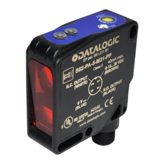
CONNECTIONS
M12 connector
TECHNICAL DATA
S62..B
Power supply:
Ripple:
Consumption
(output current excluded):
Outputs:
PNP or NPN N.O. / N.C.; 30 Vdc max. (short-circuit protection)
Output current:
Output saturation voltage:
Response time:
Switching frequency:
Emission type:
RED LASER Class 1
EN 60825-1 (2014)
Operating distance (typical values):
refer to TAB.1
Min. detectable object dimension:
Indicators:
Setting:
Functioning temperature:
Storage temperature:
Dielectric strength:
Insulating resistance:
Ambient light rejection:
0.5 mm amplitude, 10 ... 55 Hz frequency, for every axis (EN60068-2-6)
Vibrations:
Shock resistance:
Housing material:
Lens material:
Mechanical protection:
Connections:
Weight:
S62...B SETTING
S62...B alignment:
- Position the sensor and reflector aligned on opposite sides at the desired distance.
- Turn to maximum the sensitivity adjustment trimmer (ADJ.) (clockwise).
- Determine the powering on and powering off points of the yellow LED (OUT) by moving
vertically and horizontally the sensor and mount the
sensor in the middle of the points found.
Control:
-
Enter laterally the object inside the operating
field
and control that the yellow LED turns on.
-
Remove the object and check that the yellow
LED
turns off immediately
S62...C setting:
Position the sensor and turn the sensitivity trimmer at minimum: the yellow LED is OFF. Place the target opposite the
sensor.
Turn the sensitivity trimmer clockwise until the yellow LED turns ON (Target detected state, pos.A).
Remove the target, the yellow LED turns OFF. Turn the trimmer clockwise until the yellow LED turns ON (Background detected state,
pos.B). The trimmer reaches maximum if the background is not detected.
Turn the trimmer in intermediate position C, between the two positions A and B. The green LED must be ON.
S62...B PERFORMANCES
TAB.1: Operating distances (m)
REFLECTOR (mm)
R7 (51X51)/
R1 (Ø31)
R2 (Ø63)
R6 (60x40)
R20 (Ø63)
0.3 ... 16
0.3 ... 20
0.4 ... 22
0.3 ... 22
Note: The use of the RT 3970 reflecting tape is not suggested.
S62..C
10 ... 30 Vcc
2 Vpp max.
30 mA max
100 mA max (overload and overvoltage protection)
2 V
200 s
2.5 kHz
RED LASER ( = 645...665 nm): Class 2 EN 60825-1 (2014)
Class II CDRH 21 CFR PART 1040.10Pulsed emission: pot.
max 5 mW; pulse duration = 5s; frequency max = 32 KHz
1m on 90% white target (EG2)
0.5 mm at 0.5m (minimum spot)
OUTPUT LED (YELLOW) / POWER ON LED (GREEN)
Monoturn sensitivity adjustment trimmer
-10 ... 55 °C
-20 ... 70 °C
500 Vac 1 min., between electronics and housing
>20 M 500 Vdc, between electronics and housing
according to EN 60947-5-2
11 ms (30 G) 6 shock for every axis (EN60068-2-27)
ABS
PMMA window, polycarbonate lenses
IP67
M12 4-pole connector
40 g. max.
spot diameter (mm)
R8
(19X10)
0.2 ... 2
distance (mm)
DIMENSIONS
SENSITIVITY TRIMMER
POWER ON LED
OUTPUT LED
SAFETY PRECAUTIONS
All the electric and mechanical safety regulations have to be
respected during sensor functioning.
The sensor has to be protected against mechanical damage.
Apply the labels supplied in a visible position near the laser
emission beam.
S62..C:
Do not stare directly into the laser beam!
Do not point the laser beam towards people!
Eye irradiation superior to 0.25 seconds is dangerous.
Please refer to the Class 2 Standard (EN60825-1).
These sensors can not be used for safety applications!
The sensors are NOT safety devices, and so MUST NOT be used
in the safety control of the machines where installed.
Datasensing S.r.l.
Strada S. Caterina 235 - 41122 Modena - Italy
A
C
Tel: +39 059 420411 - Fax: +39 059 253973 - www.datasensing.com
B
The warranty period for this product is 36 months. See General Terms and
MIN
MAX
Conditions of Sales for further details.
For information about the disposal of Waste Electrical
and Electronic Equipment (WEEE), please refer to the
website at www.datasensing.com.
© 2008 - 2022 Datasensing S.r.l ALL RIGHTS RESERVED. Without
limiting the rights under copyright, no part of this documentation may be
reproduced, stored in or introduced into a retrieval system, or transmitted
in any form or by any means, or for any purpose, without the express
written permission of Datasensing S.r.l. ♦ Datasensing and the
Datasensing logo are trademarks of Datasensing S.r.l. ♦ Datalogic and the
Datalogic logo are registered trademarks of Datalogic S.p.A. in many
countries, including the U.S and the E.U.
826003258 Rev. I
RECEIVER
EMITTER
mm
Advertisement

Subscribe to Our Youtube Channel
Related Manuals for Datalogic S62-PL B Series


Summary of Contents for Datalogic S62-PL B Series
- Page 1 0.4 … 22 0.3 … 22 0.2 … 2 Datasensing logo are trademarks of Datasensing S.r.l. ♦ Datalogic and the Datalogic logo are registered trademarks of Datalogic S.p.A. in many Note: The use of the RT 3970 reflecting tape is not suggested.
- Page 2 Form, mittels irgendwelcher Methode oder für irgendwelchen Zweck übermittelt werden. ♦ Datasensing und das Logo von Datasensing sind Handelsmarken von Datasensing S.r.l. ♦ Datalogic und das Logo von Datalogic sind eingetragene Abstand (m) Handelsmarken von Datalogic S.p.A. in vielen Ländern, einschließlich den USA und der EU.
- Page 3 écrite expresse de Datasensing S.r.l. ♦ Datasensing et le logo Datasensing N.B.: Il est déconseillé d'utliser de la pellicule réfléchissante RT3970. sont des marques de commerce de Datasensing S.r.l. ♦ Datalogic et le logo Datalogic sont des marques de commerce de Datalogic S.p.A. déposées dans de nombreux pays, y compris les États Unis et l'Union Européenne.
- Page 4 Datasensing TAB.1: Distanze operative (m) S.r.l. ♦ Datasensing e il logo Datasensing sono marchi di Datasensing S.r.l. ♦ Datalogic e il logo Datalogic sono marchi registrati di Datalogic RIFLETTORE (mm) S.p.A. depositati in diversi paesi, tra cui U.S.A. e UE.
Need help?
Do you have a question about the S62-PL B Series and is the answer not in the manual?
Questions and answers