Table of Contents
Advertisement
Quick Links
INSTALLATION MANUAL
Hx 3 ZONE CONTROL MODULE
MODELS: S1-ZMC401A
General information . . . . . . . . . . . . . . . . . . . . . . . . . . . . . . . . . . . . 2
Hx 3 Zone Control Module kit . . . . . . . . . . . . . . . . . . . . . . . . . . . . . . . . . . .2
Safety considerations . . . . . . . . . . . . . . . . . . . . . . . . . . . . . . . . . . . 2
Understanding the Hx 3 Zone Control Module . . . . . . . . . . . . . . . 3
Limitations . . . . . . . . . . . . . . . . . . . . . . . . . . . . . . . . . . . . . . . . . . . . . . . . .3
Hx 3 Touch Screen Thermostat software requirements . . . . . . . . . . . . . . .3
Hx 3 Zone Control Module layout . . . . . . . . . . . . . . . . . . . . . . . . . . . . . . . .4
LED and LCD functionality . . . . . . . . . . . . . . . . . . . . . . . . . . . . . . . . . . . . .9
Location . . . . . . . . . . . . . . . . . . . . . . . . . . . . . . . . . . . . . . . . . . . . . . . . . .14
Mounting the Hx 3 Zone Control Module . . . . . . . . . . . . . . . . . . . . . . . . .14
Wiring . . . . . . . . . . . . . . . . . . . . . . . . . . . . . . . . . . . . . . . . . . . . . . . . . . . .15
Zoning system installation . . . . . . . . . . . . . . . . . . . . . . . . . . . . . . 19
Part 1: Prepare for zoning system installation . . . . . . . . . . . . . . . . . . . . .19
Part 2: Install the zoning system components . . . . . . . . . . . . . . . . . . . . .20
Part 3: Complete initial power-up . . . . . . . . . . . . . . . . . . . . . . . . . . . . . . .21
Part 4: Configure equipment and zoning components . . . . . . . . . . . . . . .21
Part 5: Configure settings . . . . . . . . . . . . . . . . . . . . . . . . . . . . . . . . . . . . .25
Part 6: Instruct the homeowner . . . . . . . . . . . . . . . . . . . . . . . . . . . . . . . .28
Zoning system settings . . . . . . . . . . . . . . . . . . . . . . . . . . . . . . . . 28
Accessing zone settings . . . . . . . . . . . . . . . . . . . . . . . . . . . . . . . . . . . . . .28
Heat/cool changeover time . . . . . . . . . . . . . . . . . . . . . . . . . . . . . . . . . . .28
Damper timing . . . . . . . . . . . . . . . . . . . . . . . . . . . . . . . . . . . . . . . . . . . . .29
Airflow bleeding . . . . . . . . . . . . . . . . . . . . . . . . . . . . . . . . . . . . . . . . . . . .29
Maximum airflow for individual zones . . . . . . . . . . . . . . . . . . . . . . . . . . .32
Zone names . . . . . . . . . . . . . . . . . . . . . . . . . . . . . . . . . . . . . . . . . . . . . . .37
Zone safeties . . . . . . . . . . . . . . . . . . . . . . . . . . . . . . . . . . . . . . . . . . . . . .38
Zoning system software updates . . . . . . . . . . . . . . . . . . . . . . . . . 38
Johnson Controls Ducted Systems
LIST OF SECTIONS
Main Control and zone thermostats . . . . . . . . . . . . . . . . . . . . . . . . . . . . 39
Hx 3 Zone Control Module . . . . . . . . . . . . . . . . . . . . . . . . . . . . . . . . . . . 39
Hx 3 Zone Control Module - LCD and features . . . . . . . . . . . . . . 41
Using the LCD . . . . . . . . . . . . . . . . . . . . . . . . . . . . . . . . . . . . . . . . . . . . 41
Incomplete profile . . . . . . . . . . . . . . . . . . . . . . . . . . . . . . . . . . . . . . . . . . 41
Unassigned zone sensor . . . . . . . . . . . . . . . . . . . . . . . . . . . . . . . . . . . . 42
Component miswire . . . . . . . . . . . . . . . . . . . . . . . . . . . . . . . . . . . . . . . . 42
General display . . . . . . . . . . . . . . . . . . . . . . . . . . . . . . . . . . . . . . . . . . . . 43
Active faults . . . . . . . . . . . . . . . . . . . . . . . . . . . . . . . . . . . . . . . . . . . . . . 43
Software updates . . . . . . . . . . . . . . . . . . . . . . . . . . . . . . . . . . . . . . . . . . 44
Zone settings . . . . . . . . . . . . . . . . . . . . . . . . . . . . . . . . . . . . . . . . . . . . . 44
Sensor status - Primary Zone Module only . . . . . . . . . . . . . . . . . . . . . . 44
System status - Primary Zone Module only . . . . . . . . . . . . . . . . . . . . . . 45
Auto detection - Primary Zone Module only . . . . . . . . . . . . . . . . . . . . . . 45
Configurations - Primary Zone Module only . . . . . . . . . . . . . . . . . . . . . . 46
Test mode - Primary Zone Module only . . . . . . . . . . . . . . . . . . . . . . . . . 46
Zone system faults . . . . . . . . . . . . . . . . . . . . . . . . . . . . . . . . . . . . . . . . . 50
Restore defaults . . . . . . . . . . . . . . . . . . . . . . . . . . . . . . . . . . . . . . . . . . . 51
Repair . . . . . . . . . . . . . . . . . . . . . . . . . . . . . . . . . . . . . . . . . . . . . . . 52
Restoring system defaults . . . . . . . . . . . . . . . . . . . . . . . . . . . . . . . . . . . 52
Configuring zone thermostat addresses . . . . . . . . . . . . . . . . . . . . . . . . . 52
5594275-UIM-B-1020
Advertisement
Table of Contents

Related Manuals for Johnson Controls S1-ZMC401A


Summary of Contents for Johnson Controls S1-ZMC401A
-
Page 1: Table Of Contents
Zone safeties ..........38 Zoning system software updates ......38 Johnson Controls Ducted Systems 5594275-UIM-B-1020... -
Page 2: Section I: General Information
WARNING indicates a potentially hazardous situation, which, if not avoided, could result in death or serious injury. CAUTION indicates a potentially hazardous situation, which, if not avoided may result in minor or moderate injury. It is also used to alert against unsafe practices and hazards involving only property damage. Johnson Controls Ducted Systems... -
Page 3: Understanding The Hx 3 Zone Control Module
Limitations NOTICE Compatible Communicating Equipment Models The Hx 3 Zone Control Module (S1-ZMC401A) is only compatible with the communicating equipment models listed below. Furnaces: TM8V*, TMLV*, TM9V*, YPLC*, CPLC*, LPLC*, TPLC*, YP9C*, CP9C*, LP9C*, TP9C* Air Handlers: AVC*, AVV*, MVC*... -
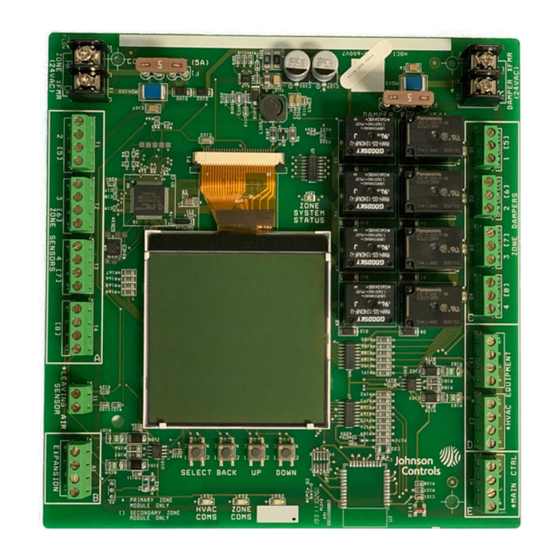
Page 4: Hx 3 Zone Control Module Layout
If the indoor equipment R wire is con- nected in Quadrant D, do not connect an additional transformer to this connection. Johnson Controls Ducted Systems... - Page 5 5594275-UIM-B-1020 A1146-001 Figure 2: Hx 3 Zone Control Module board layout Johnson Controls Ducted Systems...
- Page 6 5594275-UIM-B-1020 Table 4: Zone damper terminal designations Signal Definition Label Damper close output Damper power closed Damper common output Damper common Damper open output Damper power open Figure 3: Hx 3 Zone Control Module Johnson Controls Ducted Systems...
- Page 7 Figure 4: Hx 3 Touch Screen Thermostat (Main Control), HVAC equipment input, damper power input, and zone damper outputs Table 5: Communication terminal designations Signal Definition Label Data Non-inverted signal Low-voltage power hot 24 VAC (hot) Low-voltage power common and data ground 24 VAC (common) Data Inverted signal Johnson Controls Ducted Systems...
- Page 8 See Table 6 and Figure 6 for OEM recommended wire color, gauge, and terminations. Table 6: Communication wire color Wire color Wire gauge Label Green 18 – Solid Copper 18 – Solid Copper Black 18 – Solid Copper White 18 – Solid Copper Johnson Controls Ducted Systems...
-
Page 9: Outdoor Unit
The LED labeled ZONE SYSTEM STATUS indicates the active system status for the heating, cooling, and fan only modes. When the system is operating in heating, cooling, or fan only mode or faults and events are active, the corresponding LED color is displayed. Johnson Controls Ducted Systems... - Page 10 COM ERROR – ZM PRIM Solid Measure (voltage) R and C terminals - with Primary Zone Module Primary Zone Module power. Voltage must be greater than 24 VAC and less than 32 VAC. Table continued on next page Johnson Controls Ducted Systems...
- Page 11 COM ERROR – ZONE 5 Solid with zone 5 switch settings. Measure (voltage) R and C terminals - zone sensor power. Voltage must be greater than 24 VAC and less than 32 VAC. Table continued on next page Johnson Controls Ducted Systems...
- Page 12 LAS LOW – COOL Solid than installer setting for Ensure there is proper system refriger- cool mode ation charge. Check the equipment technical literature. Ensure there is proper airflow across the indoor coil Table continued on next page Johnson Controls Ducted Systems...
- Page 13 Remove system power. Remove the LEGACY – INDOOR EQUIP Solid miswire found in Quadrant legacy indoor equipment from the sys- A, B, D, or E tem because it is not supported. Table continued on next page Johnson Controls Ducted Systems...
-
Page 14: Location
1. Use the back of the plastic housing to mark four holes on a flat surface near the indoor equipment. 2. Use an 1/8 in. drill bit to drill the four holes where marked in step 1. 3. Use the screws provided to attach the Hx 3 Zone Control Module over the pre-drilled holes. Johnson Controls Ducted Systems... -
Page 15: Wiring
The communicating system is connected by four wires. Two of the wires are used to bring power to the individual zoning components (R and C), and three of the wires are used for serial communication (A+, C, and B-). Note: For variable capacity outdoor equipment applications, do not connect the indoor 24 VAC R connection to the outdoor equipment. Johnson Controls Ducted Systems... - Page 16 ZONES *1-4 AIR CONDITIONER/HEAT PUMP COMMUNICATING CONTROL MAIN CONTROL COMMUNICATING CONTROL NOTICE Do not connect the R connection to variable capacity outdoor equipment. Figure 8: Power open/power close (three-wire) damper application - example with four zones Johnson Controls Ducted Systems...
- Page 17 ZONES *1-4 AIR CONDITIONER/HEAT PUMP COMMUNICATING CONTROL MAIN CONTROL COMMUNICATING CONTROL NOTICE Do not connect the R connection to variable capacity outdoor equipment. Figure 9: Power open/power close (three-wire) damper application - example with eight zones Johnson Controls Ducted Systems...
- Page 18 DAMPERS) of the Hx 3 Zone Control Module. Note the following: • Use the Primary Zone Module for zones 1–4. • Use the Secondary Zone Module for zones 5–8 if applicable. Note: See Figure 4 for wiring connections. Johnson Controls Ducted Systems...
-
Page 19: Section Iv: Zoning System Installation
• Do not connect zone damper power to the HVAC equipment control transformer. • An external transformer is required for zone damper power. The Hx 3 Zone Control Module kit does not include a zone damper trans- former. Johnson Controls Ducted Systems... -
Page 20: Part 2: Install The Zoning System Components
• Leaving air sensor: between Quadrant A and Quadrant B on the Primary Zone Module only • Zone dampers: Quadrant C • HVAC equipment: Quadrant D on the Primary Zone Module only • Main Control (zone 1): Quadrant E on the Primary Zone Module only Johnson Controls Ducted Systems... -
Page 21: Part 3: Complete Initial Power-Up
Main Control or the Primary Zone Module. AUTO SETUP PRESS NEXT TO BEGIN AUTO SETUP NEXT A1299-001 Figure 11: Hx 3 Touch Screen Thermostat (Main Control) - Auto setup Johnson Controls Ducted Systems... - Page 22 Figure 13: Zone configuration prompt 4. Configure zone thermostat addresses if required using the Zone Address screen as shown in Figure 14. Hx 3 Touch Screen Thermostats and/or Hx 3 Zone Thermostats can act as zone thermostats. Johnson Controls Ducted Systems...
- Page 23 The Primary Zone Module searches for different types of zone sensors. ZONE SENSOR TYPES SEARCHING FOR CONTROLS... A1304-001 Figure 16: Searching for zone sensors 7. Troubleshoot component miswires using the Primary Zone Module if required. Otherwise, proceed to step 8. Johnson Controls Ducted Systems...
- Page 24 Z6: ZONE THERMOSTAT ZONE 7: Zone Sensor Z7: UNASSIGNED Z8: ZONE SENSOR RETRY REFER TO MAIN CONTROL Hx 3 Touch Screen Thermostat (Main Control) Hx 3 Zone Control Module (Primary Zone Module) Figure 18: Unassigned zones detected Johnson Controls Ducted Systems...
-
Page 25: Part 5: Configure Settings
Specify a heat dump zone. The default setting is zone 2. Allow Airflow Bleeding into Zones in Same Mode? Yes or No Allow Airflow Bleeding into Zones in Off Mode? Yes or No Allow Airflow Bleeding into Zones in Opposite Mode? Yes Yes or No Johnson Controls Ducted Systems... - Page 26 Tap Save. 8. When zone airflow settings are complete, tap Next. 9. On the Zone Names screen, change the name of each zone as required. Johnson Controls Ducted Systems...
-
Page 27: Zone Names
11. Review the Equipment Summary screen to confirm the correct number of zone sensors has been detected. EQUIPMENT SUMMARY ID EQUIP/STAGEAIR AIR HNDLR-2 OD EQUIP/STAGE HP-2 BRAND York NUMBER OF ZONES Save SETUP A1313-001 Figure 22: Equipment summary Johnson Controls Ducted Systems... -
Page 28: Part 6: Instruct The Homeowner
• Energizes the system for cooling if the system is currently in heating • Energizes the system for heating if the system is currently in cooling This setting applies when different zones in the system have simultaneous calls for heating and cooling. Johnson Controls Ducted Systems... -
Page 29: Damper Timing
(that is, zone demand). Go to the Air- flow Bleeding screen on the Main Control or the Primary Zone Module to adjust airflow bleeding settings as required. See Figure 27. Johnson Controls Ducted Systems... - Page 30 DUMP ZONE: ZONES IN SAME MODE? ZONE 02 BACK NEXT SELECT = SAVE SELECT = SAVE Hx 3 Touch Screen Thermostat (Main Control) Hx 3 Zone Control Module (Primary Zone Module) A1318-001 Figure 27: Airflow bleeding Johnson Controls Ducted Systems...
- Page 31 • If the maximum airflow of an individual zone is set lower than the minimum airflow of the indoor equipment, or if excess airflow is allowed to bleed into zones in same, off, or opposite mode, the Main Control or the Primary Zone Module displays a warning as shown in Figure Johnson Controls Ducted Systems...
-
Page 32: Maximum Airflow For Individual Zones
If the maximum airflow setting of the zone is less than the minimum airflow of the indoor equipment, the Hx 3 Zone Control Module bleeds excess airflow into zones that do not have a call for conditioning. Johnson Controls Ducted Systems... - Page 33 Figure 32. The warning shows the affected zone and indicates that the airflow bleeding functionality will apply. Depending on the installation conditions, do one of the following: • Increase the airflow to some or all zones • Reconfigure the zone layout of the site Johnson Controls Ducted Systems...
- Page 34 Figure 34 shows the Main Control and the Primary Zone Module when the option to perform a forced airflow test is not available. Figure 35 shows the Main Control and the Primary Zone Module when the option to perform a forced airflow test is available. Johnson Controls Ducted Systems...
- Page 35 You can view the following on the screens of the different zoning components (see Figure 36): • The minimum and maximum CFM of the indoor equipment • The CFM settings of the individual zone Johnson Controls Ducted Systems...
- Page 36 • If a forced airflow test is in progress and the indoor blower has communicated its active CFM (meaning the requested CFM has been delivered to the zone being tested), the active system CFM is displayed on the screens of the different zoning components, as shown in Figure 38. Johnson Controls Ducted Systems...
-
Page 37: Zone Names
Note: You cannot create a custom name for a zone using the Primary Zone Module. Use the Hx 3 Touch Screen Thermostat (Main Control or Zone Thermostat-Hx) or the Hx Thermostat app (for homeowners) to create custom names. NOTICE Custom zone names are limited to a maximum of 15 characters. Johnson Controls Ducted Systems... -
Page 38: Zone Safeties
• Zone Thermostats - Hx 3 Touch Screen Thermostat (Zone Thermostat-Hx) and Hx 3 Zone Thermostat (Zone Thermostat) • Hx 3 Zone Control Module - Primary Zone Module and Secondary Zone Module When software updates are complete, the components display the screen shown before the software update, for example, the Home screen. Johnson Controls Ducted Systems... -
Page 39: Main Control And Zone Thermostats
• The Zone System Status LED on the Primary Zone Module shows as green, and a progress bar is displayed in the middle of the screen. • The Zone System Status LED on the Secondary Zone Module shows as yellow and the General Display screen is shown. See Figure 43. Johnson Controls Ducted Systems... - Page 40 • The Zone System Status LED on the Secondary Zone Module shows as yellow and the General Display screen is shown. See Figure 45. Johnson Controls Ducted Systems...
-
Page 41: Section Vii: Hx 3 Zone Control Module - Lcd And Features
Complete the initial zone system profile through the auto setup process on the Main Control before accessing the Zone Settings screen (installer settings) on the Hx 3 Zone Control Module. The Profile Incomplete screen displays on the Primary Zone Module and the Secondary Zone Module until the zone system profile is configured on the Main Control. Johnson Controls Ducted Systems... -
Page 42: Unassigned Zone Sensor
See Figure 48. Perform the action shown on the Component Miswire screen. In the example shown in Figure 48, the action is to remove a leg- acy zone module from the system. When the component miswire is corrected, press Select on the Primary Zone Module to clear the miswire fault. Johnson Controls Ducted Systems... -
Page 43: General Display
If active faults are present and you press the Select, Back, Up, or Down buttons on the Hx 3 Zone Control Module, the Active Fault screen is displayed. The Active Fault screen shows the active fault with the highest priority. See Figure 50. Johnson Controls Ducted Systems... -
Page 44: Software Updates
Zone sensor status information is view only. You can only view the Zone Sensor Status screen on the Primary Zone Module. See Figure 52. The number of pages available for view reflects the number of zones configured on the zoning system. Johnson Controls Ducted Systems... -
Page 45: System Status - Primary Zone Module Only
Use the Discover option on the Primary Zone Module to determine the new zone sensor types and the number of zone sensors. You do not need to use the Restore Defaults option. Johnson Controls Ducted Systems... -
Page 46: Configurations - Primary Zone Module Only
All zones must be in off mode before you can perform a forced zone airflow test or a damper test. When there is an active system demand or another test mode is in use, test modes are not available. System Active is displayed on the screen in place of the test mode name. See the examples in Figures 56 and 57. Johnson Controls Ducted Systems... - Page 47 PAGE 1 OF 1 BYPASS ASCD TIMER BYPASS ASCD TIMER BYPASS TIMER: FORCED ZONE AIRFLOWS FORCED ZONE AIRFLOWS DAMPER TEST SELECT = CONTINUE SELECT = CO NTINUE SELECT = BYPASS SELECT = BYPASS Figure 58: Bypass ASCD timer Johnson Controls Ducted Systems...
- Page 48 3. On the Automated Test screen, use the Up and Down buttons to change the damper output time and test time if required. 4. Press Select to confirm you want to start the test. While the test is running, you can press Back at any time to end the test. Johnson Controls Ducted Systems...
- Page 49 SELECT = START TEST SELECT = START TEST SELECT = START TEST SELECT = START TEST BACK = END TEST BACK = END TEST BACK = END TEST BACK = END TEST A1353-001 Figure 60: Damper test Johnson Controls Ducted Systems...
-
Page 50: Zone System Faults
PAGE 1 OF 1 PRIMARY ZONE: VIEW STORED FAULTS VIEW STORED FAULTS CLEAR PRIMARY LOG: CLEAR STORED FAULTS SELECT = CONTINUE SELECT = CONTINUE SELECT = CLEAR SELECT = CLEAR Figure 61: Primary Zone Module - zone system faults Johnson Controls Ducted Systems... -
Page 51: Restore Defaults
HOLD SELECT FOR 5 SECONDS TO RESTORE RESTORE DEFAULTS RESTORE DEFAULTS SYSTEM DEFAULTS: SYSTEM RESTORE SYSTEM RESTORE SELECT = CONTINUE SELECT = CONTINUE SELECT = RESTORE SELECT = RESTORE Figure 63: Secondary Zone Module - restore system defaults Johnson Controls Ducted Systems... -
Page 52: Section Viii: Repair
HVAC Modbus and the zone Modbus. Configure the zone thermostat address using the Zone Address screen. See Figure 14. Subject to change without notice. Published in U.S.A. 5594275-UIM-B-1020 Copyright © 2019 by Johnson Controls. All rights reserved. Supersedes: 5594275-UIM-A-1119 York International Corp. 5005 York Drive...
Need help?
Do you have a question about the S1-ZMC401A and is the answer not in the manual?
Questions and answers