Advertisement
Quick Links
Single-Block Multi-Function Gas Control Valves
Application
© 1997 Johnson Controls, Inc.
Part No. 24-8711-5, Rev. —
Code No. LIT-121895
Gas Combustion Combination Controls and Systems Section G
GS Series
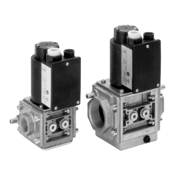
Figure 1: GS Series Single-Block Multi-Function
The GS Series single-block multi-function gas control valves provide for
protection and control of atmospheric and forced draft gas burners in
industrial and commercial heating installations. Optional sizing of body
flanges offers greater application flexibility. Valves are approved to
European and North American standards.
Typical applications include commercial and industrial boilers,
commercial and industrial burners and ovens, rooftop units, make up air
heaters, hot water heaters, kilns, and paint booths.
These single-block multi-function gas control valves offer single unit
control, replacing multiple components in a gas-train assembly, such as
on-off gas valves, gas pressure regulators, and modulating gas valves.
Options include adjustable start gas and slow open function, spring and
servo regulators, and gas/air ratio control.
Gas Control Valves
Installation Sheets Manual 121
Technical Bulletin GS
Issue Date 0297
1
Advertisement

Related Manuals for Johnson Controls GS-20 Series


Summary of Contents for Johnson Controls GS-20 Series
- Page 1 Options include adjustable start gas and slow open function, spring and servo regulators, and gas/air ratio control. © 1997 Johnson Controls, Inc. Part No. 24-8711-5, Rev. — Code No. LIT-121895...
- Page 2 Table 1: Specifications Types of Gas Natural and Liquid Petroleum (LP) Gas Maximum Operating Pressure 5 psi (350 mbar) Maximum Inlet Pressure 5 psi (350 mbar) on shutoff valves 3 psi (200 mbar) with pressure regulator Maximum Differential Pressure 8 inches W.C. (20 mbar) (GS-_03_) 20 inches W.C.
- Page 3 Check the power supply voltage for compatibility with the required valve voltage. For valves with 24 volt coils, use only NEC Class 2 transformers, such as the Johnson Controls Y65 transformer. Note: The Y65 transformer must be mounted to a grounded metal enclosure.
- Page 4 An optional thread lubricant may have been factory applied to the first two or three threads of the inlet and outlet to avoid galling. Use an approved pipe joint sealing compound on male threads before assembly. Take care to see that excess compound is removed after mounting the flanges to the pipe work.
- Page 5 Connection of the The internal diameter of the impulse tubes for the combustion air (P ) and Impulse Lines on the combustion chamber pressure, (P ) should be 5/32 inch (4.0 mm) (see the GS-406_ Figure 4). Make the connections as short as possible and route to prevent the entry of condensate into the controller.
- Page 6 Pressure regulator adjustment must be made in conjunction with the gas Adjustments appliance. See each version for specific adjustments. Version GS-_01_ This valve provides manual flow adjustment throughout the full range from zero to maximum flow. Flow adjustment is accessible below the metal plate on top of the valve cover.
- Page 7 Figure 5: Plug Screw Position 5-50 Figure 6: P Setting The start gas pressure (P ) remains at the set level until the plug screw is replaced and tightened. The pressure then rises to the setpoint (P > P Requirement: P Now P can be adjusted.
- Page 8 Start repetitions require an interim pause of approximately 20 seconds for the evacuation of the pressure chamber. With test pressure for external leakage applied, adjust pointer on scale (P to white dot within curved ramp (see Figure 6). Version GS-406_ For a typical installation, see Figure 8.
- Page 9 Figure 9: Zero Setpoint and Gas/Air Ratio Adjustment 0.7:1 0.6:1 (Inches W.C.) (Inches W.C.) Figure 10: Analysis Chart With burner in maximum load position, the gas/air ratio must be adjusted on the scale (R) to meet the desired flue gas analysis readings. Then check the flue gas analyses on low and high settings without manipulating the adjustments, and thereafter, revise the settings if necessary.
- Page 10 Set the burner to the maximum load and make flue gas analysis. Then adjust the outlet pressure against the scale (R) until the desired flue gas analysis readings are obtained. Check the flue gas analysis readings on the low and high settings without manipulating adjustments.
-
Page 11: Repairs And Replacement
Field repairs must not be made, except to replace the filter or strainer. For Repairs and a replacement filter, strainer, replacement valves, or other accessories, Replacement contact the nearest Johnson Controls wholesaler or the original equipment manufacturer. CAUTION: Label all wires prior to disconnection when servicing valves. Wiring errors can cause improper and dangerous operation. - Page 12 Notes Controls Group FAN 121 507 E. Michigan Street Installation Sheets Manual P.O. Box 423 Printed in U.S.A. Milwaukee, WI 53201 12 G Gas Combustion Combination Controls and SystemsGS Series Single-Block Gas Control Valves...
Need help?
Do you have a question about the GS-20 Series and is the answer not in the manual?
Questions and answers